EP1426286A1 - Vorrichtung, insbesondere ein Boot oder ein Schwimmbad, mit einem aufblasbaren Gehäuse, das ein integriertes Gerät behinhaltet - Google Patents
Vorrichtung, insbesondere ein Boot oder ein Schwimmbad, mit einem aufblasbaren Gehäuse, das ein integriertes Gerät behinhaltet Download PDFInfo
- Publication number
- EP1426286A1 EP1426286A1 EP03292941A EP03292941A EP1426286A1 EP 1426286 A1 EP1426286 A1 EP 1426286A1 EP 03292941 A EP03292941 A EP 03292941A EP 03292941 A EP03292941 A EP 03292941A EP 1426286 A1 EP1426286 A1 EP 1426286A1
- Authority
- EP
- European Patent Office
- Prior art keywords
- inflatable
- accessory
- trunk
- enclosure
- wall
- Prior art date
- Legal status (The legal status is an assumption and is not a legal conclusion. Google has not performed a legal analysis and makes no representation as to the accuracy of the status listed.)
- Granted
Links
- 238000007789 sealing Methods 0.000 claims abstract description 14
- 230000009182 swimming Effects 0.000 claims abstract description 10
- 230000002787 reinforcement Effects 0.000 claims description 20
- 239000000463 material Substances 0.000 claims description 9
- 230000002093 peripheral effect Effects 0.000 claims description 7
- 238000003466 welding Methods 0.000 claims description 7
- 239000012530 fluid Substances 0.000 claims description 5
- 238000005304 joining Methods 0.000 claims description 4
- 238000004026 adhesive bonding Methods 0.000 claims description 3
- 230000000284 resting effect Effects 0.000 claims description 3
- 239000007788 liquid Substances 0.000 description 7
- 238000003860 storage Methods 0.000 description 6
- XLYOFNOQVPJJNP-UHFFFAOYSA-N water Substances O XLYOFNOQVPJJNP-UHFFFAOYSA-N 0.000 description 6
- 235000013580 sausages Nutrition 0.000 description 4
- 238000009434 installation Methods 0.000 description 3
- 230000000717 retained effect Effects 0.000 description 3
- VYZAMTAEIAYCRO-UHFFFAOYSA-N Chromium Chemical compound [Cr] VYZAMTAEIAYCRO-UHFFFAOYSA-N 0.000 description 2
- 241001441732 Ostraciidae Species 0.000 description 2
- 239000000446 fuel Substances 0.000 description 2
- 229920002994 synthetic fiber Polymers 0.000 description 2
- 241000735470 Juncus Species 0.000 description 1
- 240000008042 Zea mays Species 0.000 description 1
- 238000009530 blood pressure measurement Methods 0.000 description 1
- 238000009529 body temperature measurement Methods 0.000 description 1
- 238000010586 diagram Methods 0.000 description 1
- 238000000605 extraction Methods 0.000 description 1
- 239000004744 fabric Substances 0.000 description 1
- 238000007667 floating Methods 0.000 description 1
- 235000013305 food Nutrition 0.000 description 1
- 238000012423 maintenance Methods 0.000 description 1
- 230000014759 maintenance of location Effects 0.000 description 1
- 238000004519 manufacturing process Methods 0.000 description 1
- 238000005259 measurement Methods 0.000 description 1
- 238000000034 method Methods 0.000 description 1
- 230000004048 modification Effects 0.000 description 1
- 238000012986 modification Methods 0.000 description 1
- 238000003032 molecular docking Methods 0.000 description 1
- 238000007747 plating Methods 0.000 description 1
- 238000011084 recovery Methods 0.000 description 1
- 238000000638 solvent extraction Methods 0.000 description 1
- 229910001220 stainless steel Inorganic materials 0.000 description 1
- 239000010935 stainless steel Substances 0.000 description 1
- 239000011232 storage material Substances 0.000 description 1
- 238000006467 substitution reaction Methods 0.000 description 1
- 230000004083 survival effect Effects 0.000 description 1
- 230000003313 weakening effect Effects 0.000 description 1
- 238000004804 winding Methods 0.000 description 1
Images

Classifications
-
- B—PERFORMING OPERATIONS; TRANSPORTING
- B63—SHIPS OR OTHER WATERBORNE VESSELS; RELATED EQUIPMENT
- B63B—SHIPS OR OTHER WATERBORNE VESSELS; EQUIPMENT FOR SHIPPING
- B63B21/00—Tying-up; Shifting, towing, or pushing equipment; Anchoring
- B63B21/04—Fastening or guiding equipment for chains, ropes, hawsers, or the like
- B63B21/045—T-shaped cleats
-
- B—PERFORMING OPERATIONS; TRANSPORTING
- B63—SHIPS OR OTHER WATERBORNE VESSELS; RELATED EQUIPMENT
- B63B—SHIPS OR OTHER WATERBORNE VESSELS; EQUIPMENT FOR SHIPPING
- B63B7/00—Collapsible, foldable, inflatable or like vessels
- B63B7/06—Collapsible, foldable, inflatable or like vessels having parts of non-rigid material
- B63B7/08—Inflatable
- B63B7/085—Accessories or mountings specially adapted therefor, e.g. seats, sailing kits, motor mountings
-
- E—FIXED CONSTRUCTIONS
- E04—BUILDING
- E04H—BUILDINGS OR LIKE STRUCTURES FOR PARTICULAR PURPOSES; SWIMMING OR SPLASH BATHS OR POOLS; MASTS; FENCING; TENTS OR CANOPIES, IN GENERAL
- E04H4/00—Swimming or splash baths or pools
- E04H4/0018—Easily movable or transportable swimming pools
- E04H4/0025—Easily movable or transportable swimming pools with inflatable parts
-
- B—PERFORMING OPERATIONS; TRANSPORTING
- B63—SHIPS OR OTHER WATERBORNE VESSELS; RELATED EQUIPMENT
- B63B—SHIPS OR OTHER WATERBORNE VESSELS; EQUIPMENT FOR SHIPPING
- B63B25/00—Load-accommodating arrangements, e.g. stowing, trimming; Vessels characterised thereby
- B63B25/002—Load-accommodating arrangements, e.g. stowing, trimming; Vessels characterised thereby for goods other than bulk goods
Definitions
- the present invention relates to improvements brought to the devices constituted by or comprising at least one inflatable enclosure delimited by at least one flexible wall and at least one accessory secured to said flexible wall of the enclosure.
- the provisions of the invention can find application in all types of devices comprising at minus an inflatable enclosure of any type. It seems, however, that they must find a preferred application in inflatable boats which whatever the specific arrangement (with flexible hull, with rigid hull) and in inflatable pools whatever the constitution of the inflatable side, being heard that other types of devices (e.g. inflatable liferafts, flexible tanks for liquids, ...) also fall within the scope of application of the provisions of the invention.
- Pool users can also wish to have a place to group together small accessories usable in water (such as floating toys, a balloon, ...) and easily accessible from inside the pool.
- the object of the present invention is to respond to aspirations of the various users of the devices in question in an original way, either in substitution for existing solutions, either in addition to these, without resulting in additional bulk in the device nor a substantial modification of general infrastructure of the system.
- the means according to the invention are of great universality of employment and allow to ensure the mounting many types of accessories as will explained further. These means are structurally simple and therefore inexpensive to manufacture and install.
- the presence of the protruding reinforcement (rod) around the periphery of the opening, which is engaged and retained in the groove provided in at least one of the frames ensures a holding mechanics of the flexible wall all around the opening and in all directions, so that the shape and resistance of the inflatable enclosure find nothing affected by the presence of the opening: the functional combination of the reinforcement protruding peripheral and rigid frame equipped with a reinforcement receiving groove provides recovery particularly effective stressing efforts to which is subjected the flexible wall stretched by the inflation.
- the sealing means sealing the inflation fluid (a gas, usually air), a simple and effective solution is that the sealing means comprise a flexible pocket made of a waterproof material, which is secured tightly to the internal face of the wall of the inflatable enclosure around the opening, said pocket extending inside the inflatable enclosure in sealingly surrounding the above accessory.
- the tightening means are screws or bolts distributed around the perimeter of the opening, although could also consider (especially for the mounting of small accessories) that the wall bordering the opening, the inner frame and the outer frame are secured by gluing and / or welding.
- the invention relates in particular to mounting accessories such as handles, cleats or other similar devices.
- substantially rigid base for mounting the accessory, which extends at least partly inside of the enclosure and has a perimeter rim constituting the aforesaid interior frame.
- the base is substantially in the form of plate, in which case the base will extend approximately in the plane of the flexible wall and its accessory integral will project from said wall.
- the base either in the form of an open box which then extends at least partly below the level of the flexible wall and at inside the inflatable enclosure (recessed base): it thus becomes possible that the accessory is housed in the box-shaped base so that this accessory becomes at least partially embedded (for example built-in cleat), or retractable (for example extractable handle, recalled by springs inside of the base).
- the accessory has a functional part which is integral with the base or the accessory has a part which is attached to the base and fixed to it.
- the outer frame is equipped or coated externally of a hubcap.
- the means according to the invention allow the installation, on the wall of the inflatable enclosure, of a accessory of an uncommon type, namely a chest substantially rigid which extends at least in part to the interior of said inflatable enclosure and which comprises a substantially rigid rim projecting transversely to the wall of the trunk, located outside the wall of the enclosure.
- volume of the enclosure for example of the "empty" volume (ie filled with air) from the pneumatic enclosure (s) (buoyancy tubes of an inflatable boat, peripheral tube of an inflatable swimming pool or raft survival, filling volume of a flexible tank) equipping the device.
- This volume admittedly relatively important, performs an essential function in the operation of the device (in particular buoyancy for a boat, retention of a volume of water for a swimming pool, storage of a liquid for a tank);
- the volume of the inflatable enclosure (s) is largely dimensioned, in particular with regard to what would be strictly necessary.
- the invention therefore provides to divert a proportionally weak part, of this volume to assign it an additional function storage.
- the edge of the trunk is independent of the above outer frame and covers it; in this case the trunk rim is fixed by the above means of tightening, or even the trunk is secured to a single of the two frames by second fixing means separate from the above clamping means.
- the wall side of the trunk has a shoulder and that the second fastening means include screws or bolts crossing said side wall of the trunk and engaged with one of the interior or exterior frames, the heads of these screws or bolts supported on a support piece resting against the above shoulder; especially then, the support piece is unique and shaped like a frame inner peripheral contour of the trunk to reinforce this one.
- the edge of the trunk, the interior frame and possibly the second outer frame are substantially planar.
- the trunk can be equipped with all the means necessary for its function and its environment ; cover (removable, sliding or pivoting), closing lock, gasket, etc.
- the trunk can receive any desired conformation, in particular parallelepiped, in particular parallelepiped elongated rectangle, which fits more easily into a elongated enclosure such as a rod boat buoyancy or poolside.
- An accessory arrangement as defined above according to the invention can be integrated, as as needed, in many types of devices provided with at least one inflatable enclosure with at least one flexible wall, whatever the type (pneumatic, hydraulic) of inflation of said enclosure.
- the invention is particularly attached (but not exclusively) to pneumatic devices comprising at at least one sidewall comprising at least one inflatable tube pneumatically which are then made up as exposed above, the aforesaid inflatable enclosure being constituted here by said pneumatically inflatable tube which receives said accessory.
- an application more particularly referred to in the context of the present invention relates the field of inflatable boats: according to the invention, an inflatable boat comprising two lateral floats joining forward to form a bow and braced by a rigid floor and by a transom, each lateral float being formed of minus a pneumatically inflatable tube, is characterized in that this inflatable tube is equipped with at least one accessory as described above.
- Another application preferred also particularly targeted in the context of the invention relates to the field of inflatable swimming pools: according to the invention, a delimited pneumatic swimming pool perimeter by at least one inflatable tube pneumatically is characterized in that this tube is equipped with at least one accessory as described above.
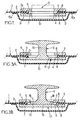
- the sealing means 10 vis-à-vis the inflation fluid can be arranged so as to completely isolate the zone of the wall 2 on which the accessory 3 is mounted from the rest of the 'enclosure 1.
- the sealing means may comprise a sheet of flexible material (in particular of the same nature and same characteristics as that constituting the wall 2) forming a flexible pocket 10 which is tightly secured to its periphery at 10 a (in particular by gluing or welding) to the internal face of the flexible wall 2 around the opening 4, said pocket 10 then extending inside the enclosure 1, sealingly surrounding the accessory 3 and its mounting parts on the wall 2.
- the two frames 6 and 7 are provided of respective grooves 8 opposite opposite defining together a retaining channel suitable for housing said reinforcement 5 which is thus retained symmetrically.
- the presence of the reinforcement or ring 5 allows to resume, on all the circumference of the opening 4, the tension forces of the wall 2 of so that the speaker does not show any weakening or no deformation and retains its general shape despite the presence of the accessory.
- the tightening means are screws or bolts (the reference 9 designating the diagrams of the axes thereof) which are distributed around the periphery of the opening 4.
- the clamping means are constituted simply by bonding and / or welding against one another the edge 2 a of the opening 4, the outer frame 6 and the inner frame 7 (the reference 2 a designating the peripheral part of the wall 2 which is sandwiched between the two frames 6, 7 and which is bordered by the rod 5).
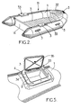
- FIG 2 is illustrated an example inflatable boat 11 likely to be affected by the invention.
- Boat 11 is a boat pneumatic which includes two pneumatic floats 1 bilaterally bordering a bottom 13 and a hull (not visible) underlying. The stern part of the boat is closed by a transom 14 secured to the bottom 13 and floats 1 and bracing them. Both floats 1 join forward to form a bow.
- each float 1 is consisting of a pneumatically inflatable tube.
- Each float 1 (or each strand constituting it) represents the inflatable enclosure mentioned previously at Figure 1.
- the specific type of boat (hull flexible, rigid hull, equipment) does not consideration in the context of the invention.
- Boats, including boats inflatable, are equipped with traditional accessories such as carrying handles, cleats for ropes mooring, or others, which are fixed (glued, welded, bolted) in projecting position on the float.
- the arrangements according to the invention allow not only consider mounting these accessories on the wall of float 1 in their usual situation - that is to say protruding from the float - but they also make it possible to envisage an original assembly of these accessories, namely part or all mounting built-in and / or retractable.
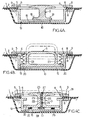
- a base is provided for substantially rigid mounting 15 for mounting accessory 3 (for example a handle or a cleat), which base 15 extends at least in part to inside enclosure 1 (i.e. below the level of the wall 2) and is provided with a rim perimeter constituting the abovementioned internal framework 7.
- the mounting base 15 and the ledge forming the inner frame 7 are located in the extension of one another and the whole presents itself generally in the form of a plate 17 provided with the groove 8 perimeter.
- the plate 17 formed by the base 15 and the inner frame 7 was made of the same material as accessory 3 (illustrated here in the form of a cleat): in this case the whole of the plate 17 and of the part functional 16 of accessory 3 can be realized under integral form as illustrated in FIG. 3A.
- accessory 3 (by example the cleat) is attached to plate 17 and fixed (for example by screwing in 18) on it as illustrated in Figure 3B.
- the mounting base 15 can be arranged substantially in the form of an open box surrounded by a rim perimeter constituting the aforesaid inner frame 7 (the entire box being designated by the reference 19).
- the accessory 3 is then fixed on the base 15 (by example by screwing 18).
- the accessory 3 is erased in part or all (case illustrated in Figure 4A) of so that the accessory is no longer likely to prove dangerous and that, moreover, the float 1 has a line continuity offering an aesthetic appearance interesting.
- the fixed mounting of accessory 3 inside the box 19 may be suitable for certain accessories such than a cleat as shown in Figure 4A.
- accessories such as a handle
- the provisions according to the invention offer the possibility of putting using a retractable accessory in part or in screen.
- FIG. 4B relates to a retractable handle, which handle then constitutes the accessory 3.
- the inner contour of the upper frame 6 is shaped so that you can grasp the top of the handle 3, slightly protruding, and pull it up when you want to use it (position illustrated in dashes).
- means can be provided to erasable ratchet (not shown) to block the handle in projecting position.
- FIG. 4C is illustrated a cleat arrangement retractable with two stable positions, retracted and extended respectively.
- the cleat 3 is provided with a body 22 which is hollowed out by a channel axial 26 which advantageously opens out, superiorly, in a recess or counterbore 23 with a flat bottom.
- a ratchet of retainer 24 has an elastic rod 25 passing through the channel 26 and ending at the top with a spout 27.
- the base 28 of the rod 25 is secured to the bottom 15 of the box 19.
- Springs 29 are interposed between the sole 30 of the stopper 3 and the bottom 15. In the retracted position of the cleat illustrated in Figure 4C, the cleat 3 is pressed in the box 19 by compressing the springs 29 and is retained by the spout 27 resting on the bottom of the recess 23. When the spout 27 is released, the springs 29 repel the cleat 3 upwards, in the extended position or in the use.
- the upper frame 6 can be coated with a cover 31, for example made of stainless steel or chrome; or it can be the senior executive 6 himself which, being made for example of synthetic material molded, has an external face which presents all desired decorative shape and which can possibly be metallized on the surface (chrome plating).
- a trunk 33 is installed as example in each of the inflatable tubes or floats 1.
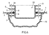
- the flange 1 has an opening 4 on the edge of which is securely fixed the trunk 33 made rigidly (for example in material plastic).
- the trunk 33 has an edge perimeter which substantially coincides closely with the edge of the opening 4 of the inflatable tube 1, the trunk being engaged for the most part, through opening 4, inside the inflatable tube.
- the edge perimeter of the trunk 33 is secured by means of fixing to said edge of opening 4 over the entire periphery of it.
- the sealing means are constituted as described above and include a flexible pocket 10 tightly secured (bonding, welding) to the internal face of the wall 2 of the tube inflatable 1 all around the opening 4.
- the trunk 33 has a substantially rigid rim 34, surrounding its edge perimeter and projecting outwards.
- the ledge 34 thus covers the edge of the opening 4 on the face outer wall 2 of the inflatable tube 1.
- a lower rigid frame 7 having substantially the same shape and dimensions that the aforesaid edge 34 of the trunk 33 and arranged inside the inflatable tube 1, against the inner face of the wall 2 thereof and facing the rim 34 of the trunk 33.
- the rim 34 of the trunk could then constitute the external frame 6 which was mentioned above, the assembly of the trunk 33 to the flexible wall 2 then by tightening the lower frame 7 and the ledge 9.
- a second frame 6 is provided outside the inflatable tube 1 and interposed between the external face of the wall 2 of said inflatable tube 1 and the rim 34 of the trunk 33.
- the assembly of the trunk 33 to the flexible wall 2 is done, as before, preferably by bolting or screwing in 9 through the flange 34, the possible frame additional exterior 6, flexible wall 2 and frame interior 7.
- the holes in the frame interior 7 can be threaded to receive ends of these screws 13.
- the trunk 33 can, of course, be provided with a suitable cover 35: removable, sliding, or preferably swivel as shown in Figure 5.
- This cover 35 is arranged in any way required for what concerns the tightness of its closure by a seal peripheral, its means of closing by lock, etc.
- the trunk 33 is arranged, in a simple manner, with a rim 34 which is substantially planar; the interior frames 7 and possibly exterior 6 are then, too, substantially plans. Due to the general curvature of the wall of inflatable tube 1, this results in tensions unevenness of this wall on the periphery of the opening 4.
- the rim 34 of the trunk 33 extends approximately in a tangent plane of the inflatable tube 1 and it follows that its edges parallel to the axis of the sausage 1 are raised relative to the sausage. Such arrangement can be considered unsightly.
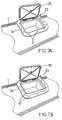
- FIG. 7A In which the two parts of the rim 34 extending transversely to the flange 1 are curved so as to match the curvature of the sausage 1.
- the interior frames and possibly outside, as well as the cover, are also curved in the same way. This creates a safe whose visible part fits perfectly, visually, in the general shape of the tube inflatable 1.
- FIG. 7B a intermediate solution illustrated in FIG. 7B, according to which the rim 34, as well as the inner frames 7 and possibly exterior 6 are curved to marry the curvature of the inflatable tube 1 in the same manner as in the embodiment of FIG. 7A, while the cover 35 remains flat as in the realization of figure 5.
- the part upper case 33 with cover 35 remains certainly slightly protruding above the curved face of the sausage 1, but the curvature of the rim 34 and the others components of the fixing means eliminates the unequal tension of the wall of the strand 1 around opening 4.
- FIG. 8A is illustrated, in exploded view and in section, another embodiment of the provisions of the Figure 5.
- the two inner 7 and outer 6 frames are provided with respective grooves 8 suitable for enclosing the reinforcement 5 forming retaining ring which is secured to the wall 2 of the inflatable tube 1.
- the two frames 6 and 7 are joined together, by enclosing said wall 2 of the tube inflatable 1, using first fastening means, by example of screws or bolts 9 (shown schematically by their axes) distributed around the reinforcement 5.
- the arrangements according to the invention constitutes a perfectly integrated storage space in the basic structure of the boat, which does not affect said structure, which can therefore be implemented whatever whatever the constitution of the boat, and who does not in any way clutter the interior space of the boat.
- the sealing means implemented works provide particularly effective protection of inflatable tube and the presence of the trunk does not affect nothing the buoyancy characteristics.
- the trunk 33 is then secured by its rim upper 34 which rests on the upper frame 6, at this single frame 6 using second fastening means such as screws or bolts 36, which in this example of implementation, extend parallel to the screws or bolts 9 cited above.
- FIG. 8B is illustrated a variant of the mode from previous realization.
- fixing the trunk 33 does not is done more by joining its rim 34 to the frame exterior 6, but is made by joining the wall lateral 37 of the trunk to one of the frames 6, 7, for example to the inner frame 7 using screws 38 extending perpendicular to the screws 8 for assembling the two frames 6, 7 with the wall 2 of the inflatable tube 1, as shown in Figure 8B.
- the wall lateral 37 of it presents an upper part of transverse dimension greater than that of the part lower, so as to form a shoulder 39 which can extend around the perimeter of the trunk or only on two faces opposite.
- the head of each screw 38 is supported by a support piece 40, that is to say that there is a support piece 40 for each screw 38, either as provided a single support piece 40, conforming to the interior contour of the trunk 33 and bearing against the shoulder 39, this single support piece 40 forming a peripheral reinforcement inside the trunk.
- FIGS. 8A and 8B allow quick and easy disassembly / reassembly of the boot 33 while ensuring good tension of the sheet material (eg coated fabric) constituting the wall 2 of the inflatable tube 1 thanks to the reinforcement 5 forming rod which is trapped in the channel defined by the two grooves 8 of the frames 6, 7 together.
- the sheet material eg coated fabric
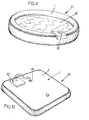
- FIG. 9 An example such a pool, designated as a whole by the reference 41, is illustrated in FIG. 9.
- the swimming pool 41 is bounded perimeter by a pneumatic tube inflatable 1 of large volume which occupies the entire height of the pool and which, below, is joined so waterproof to a bottom (not visible).
- the inflatable tube 1 can extend along a closed contour, in particular round (as illustrated) or oval, to retain a volume of water 42. Given the large volume of the inflatable tube 1 (which here constitutes the inflatable enclosure 1 mentioned more high) and of its relatively large section, it is possible to equip it with a chest 33 of rigid structure under the same conditions as set out above for equipping an inflatable buoyancy tube inflatable boat.
- the trunk 33 (which then constitutes the accessory above generically designated by 3) may be constituted as previously indicated and its connection to the tube inflatable can be performed as exposed in look at Figures 6, 8A or 8B, and use the configurations of installation on the tube illustrated in Figures 5, 7A and 7B.
- the trunk 33 can be shaped and arranged, in particular internally, in any case desirable in relation to possible use special. So, in the case of equipping a inflatable boat, the trunk can be provided with inside, fixing means and / or partitioning suitable for storing navigation equipment. Of even, in the case of the equipment of a swimming pool, the trunk can be arranged for the storage of objects / toys floats which thus remain accessible from the water. In all cases, and in particular for the equipment of a pool, we can also consider that the trunk is arranged in a cooler with the interesting advantage that being in mostly engaged inside the inflatable tube, the trunk is better protected from the sun.
- FIG 10 is illustrated yet another scope of the provisions of the invention, which relates to flexible tanks for liquids (water, fuel, ).
- the closed pocket with flexible wall which constitutes the inflatable enclosure mentioned above, the inflation of this enclosure being of hydraulic type and caused by the liquid introduced into the enclosure.
- the flexible tank 43 comprises a flexible enclosure 1, any shape, which can be fitted with a chest 33 under the same conditions as set out above for equipping an inflatable buoyancy tube inflatable boat.
- the attachment of the trunk 33 to the flexible wall 2 of the enclosure 1, in particular on the face from above, can be made as exposed previously with reference to FIGS. 6, 8A and 8B.
- Such trunk 33 can be used to receive tools necessary for the operation of reservoir 43, for example for actuation of a valve 44 controlling the introduction of the liquid in the pocket or its extraction out of the pocket, or it can be used to house control equipment (pressure measurement, temperature measurement, measurement of filling height) necessary for operating the tank.
- control equipment pressure measurement, temperature measurement, measurement of filling height
Landscapes
- Engineering & Computer Science (AREA)
- Chemical & Material Sciences (AREA)
- Combustion & Propulsion (AREA)
- Mechanical Engineering (AREA)
- Ocean & Marine Engineering (AREA)
- Architecture (AREA)
- Civil Engineering (AREA)
- Structural Engineering (AREA)
- Tents Or Canopies (AREA)
- Toys (AREA)
- Telephone Function (AREA)
- Adornments (AREA)
- Manipulator (AREA)
- Details Of Rigid Or Semi-Rigid Containers (AREA)
- Details Of Audible-Bandwidth Transducers (AREA)
- Motorcycle And Bicycle Frame (AREA)
- Devices For Medical Bathing And Washing (AREA)
Applications Claiming Priority (4)
| Application Number | Priority Date | Filing Date | Title |
|---|---|---|---|
| FR0215138 | 2002-12-02 | ||
| FR0215138A FR2847879A1 (fr) | 2002-12-02 | 2002-12-02 | Embarcation pneumatique |
| FR0301251 | 2003-02-04 | ||
| FR0301251A FR2847880B1 (fr) | 2002-12-02 | 2003-02-04 | Dispositif, notamment embarcation ou piscine, pourvu d'une enceinte gonflable equipee d'un coffre integre |
Publications (2)
| Publication Number | Publication Date |
|---|---|
| EP1426286A1 true EP1426286A1 (de) | 2004-06-09 |
| EP1426286B1 EP1426286B1 (de) | 2005-08-10 |
Family
ID=32313959
Family Applications (1)
| Application Number | Title | Priority Date | Filing Date |
|---|---|---|---|
| EP03292941A Expired - Lifetime EP1426286B1 (de) | 2002-12-02 | 2003-11-26 | Vorrichtung, insbesondere ein Boot oder ein Schwimmbad, mit einem aufblasbaren Gehäuse, das ein integriertes Gerät behinhaltet |
Country Status (8)
| Country | Link |
|---|---|
| US (1) | US7165505B2 (de) |
| EP (1) | EP1426286B1 (de) |
| AT (1) | ATE301573T1 (de) |
| AU (1) | AU2003264644B2 (de) |
| DE (1) | DE60301247T2 (de) |
| ES (1) | ES2244905T3 (de) |
| FR (1) | FR2847880B1 (de) |
| PT (1) | PT1426286E (de) |
Families Citing this family (15)
| Publication number | Priority date | Publication date | Assignee | Title |
|---|---|---|---|---|
| US7530872B2 (en) * | 2005-02-23 | 2009-05-12 | Keith Parten | Aquatic recreational system with retractable tow hook |
| US20080227069A1 (en) * | 2007-03-15 | 2008-09-18 | Lamberty Susan L | Swimming Pool Device |
| US8393285B2 (en) * | 2010-06-07 | 2013-03-12 | Gem Products, Inc. | Boat cleat assembly |
| IL214732A0 (en) * | 2011-08-18 | 2011-12-29 | Ez Pack Water Ltd | Emergency water tank with inflatable elevation device |
| US8888546B2 (en) * | 2011-10-13 | 2014-11-18 | Cheryl Meares Dykstra | Aquatic stabilizing locus preventing roving |
| USD760070S1 (en) | 2014-09-23 | 2016-06-28 | Gem Products, Inc. | Cleat |
| USD846479S1 (en) * | 2016-07-15 | 2019-04-23 | Proslide Technology Inc. | Water ride vehicle |
| USD816580S1 (en) * | 2017-03-10 | 2018-05-01 | Alpacka Raft Llc | Stern of a raft |
| US11242122B2 (en) * | 2018-03-12 | 2022-02-08 | Peter S Heberling, II | Insertable bladder system for inflatable boat repair |
| KR102251509B1 (ko) * | 2019-03-26 | 2021-05-13 | 조기상 | 이중공간직물을 이용한 고무보트 |
| US12006007B2 (en) * | 2019-12-24 | 2024-06-11 | Dirk Steinhour | Connectors for inflatable structures |
| US11572138B2 (en) * | 2021-03-04 | 2023-02-07 | Nicholas Pieschel | Inflatable stand up paddleboard with thermally insulated compartment |
| USD1022097S1 (en) | 2021-10-29 | 2024-04-09 | Nicholas Pieschel | Water sports board |
| CN219219926U (zh) * | 2022-12-12 | 2023-06-20 | 上海荣威塑胶工业有限公司 | 充气按摩水池 |
| USD1115500S1 (en) * | 2024-09-27 | 2026-03-03 | Patrick Industries, Inc. | Folding marine cleat |
Citations (4)
| Publication number | Priority date | Publication date | Assignee | Title |
|---|---|---|---|---|
| FR2259742A1 (en) * | 1974-02-01 | 1975-08-29 | Buscher Walter | Inflatable boat with central container opening - has trough formed of flexible sheet secured to reinforcement |
| DE7117265U (de) * | 1975-09-18 | Büscher, Walter, 5606 Tönisheide | Schlauchboot | |
| DE2411229A1 (de) * | 1974-03-08 | 1975-09-25 | Metzeler Ag | Aufblasbare schwimmkoerper, die in den tragschlaeuchen verschliessbare oeffnungen enthalten |
| DE20214276U1 (de) * | 2002-09-03 | 2002-11-28 | Farahat, Alaa El.Dien, 46414 Rhede | Wassertrampolin |
Family Cites Families (25)
| Publication number | Priority date | Publication date | Assignee | Title |
|---|---|---|---|---|
| US586752A (en) * | 1897-07-20 | Charles fitz roy a | ||
| US919358A (en) * | 1906-01-15 | 1909-04-27 | Thomas B Jeffery | Vehicle-wheel. |
| US1765002A (en) * | 1929-07-19 | 1930-06-17 | Air Cruisers Inc | Pneumatic water craft |
| US1864001A (en) * | 1932-04-08 | 1932-06-21 | Delphin H Spicer | Sealing means for tire valves |
| US1969118A (en) * | 1933-08-02 | 1934-08-07 | Goodrich Co B F | Valve for inflatable articles |
| US2319256A (en) * | 1942-03-28 | 1943-05-18 | American Rubber Products Corp | Tank ball |
| SE351274B (de) * | 1971-04-06 | 1972-11-20 | Trelleborgs Gummifabriks Ab | |
| DE2352235A1 (de) * | 1971-05-04 | 1975-04-24 | Walter Buescher | Motorisch getriebenes schlauchboot |
| US3843027A (en) * | 1971-12-29 | 1974-10-22 | Reynolds Metals Co | Fluid dispensing container construction |
| US3866253A (en) * | 1973-01-08 | 1975-02-18 | Dacor Corp | Divers buoyancy vest |
| DE2404690A1 (de) * | 1974-02-01 | 1975-08-14 | Walter Buescher | Motorisch getriebenes schlauchboot |
| US3903915A (en) * | 1974-02-07 | 1975-09-09 | Scovill Manufacturing Co | Valve assembly |
| US4004614A (en) * | 1975-08-01 | 1977-01-25 | Halkey-Roberts Corporation | Tether for captive plug of inflation device |
| FR2379001A1 (en) * | 1977-01-28 | 1978-08-25 | Angeviniere Sa | Inflation valve for multi-compartment inflatable dinghy - has body housed in threaded bush which is fixed in place by sealing washer and lock nut |
| FR2483855A1 (fr) * | 1980-06-06 | 1981-12-11 | Legris | Perfectionnement aux ensembles de gonflage double pour structures souples |
| US4478587A (en) * | 1982-11-16 | 1984-10-23 | Mackal Glenn H | Inflatable boat valve and mounting therefor |
| DE3436797A1 (de) * | 1984-10-06 | 1986-04-10 | Scheffer-Klute GmbH & Co, 5768 Sundern | Ventil fuer schlauchboote (folienboote) |
| DK80185A (da) * | 1985-02-21 | 1986-08-22 | Joergen Hansen | Regulerbar luftventil til et oppusteligt legeme |
| JPS62157890A (ja) * | 1985-12-31 | 1987-07-13 | Tabata:Kk | 潜水用浮力調整ジヤケツト |
| FR2627839B1 (fr) * | 1988-02-25 | 1990-06-15 | Zodiac Int | Valve pneumatique pour un objet gonflable, tel qu'un bateau pneumatique |
| US4864961A (en) * | 1988-06-14 | 1989-09-12 | Slonski Richard M | Auxiliary flotation system |
| FR2765181B1 (fr) * | 1997-06-30 | 1999-08-27 | Zodiac Int | Embase de support d'accessoires sur la paroi souple d'un corps gonflable et embarcation pneumatique ainsi equipee |
| FR2773864B1 (fr) * | 1998-01-19 | 2000-03-24 | Zodiac Int | Valve pneumatique semi-encastrable pour un objet gonflable, tel qu'un bateau pneumatique |
| FR2778146B1 (fr) * | 1998-04-29 | 2000-07-07 | Zodiac Int | Enceinte pneumatique gonflable a forme geometrique contrainte,notamment aplatie,en particulier plancher pour embarcation |
| US6080027A (en) * | 1998-10-19 | 2000-06-27 | Rodemann; Will | Flotation device |
-
2003
- 2003-02-04 FR FR0301251A patent/FR2847880B1/fr not_active Expired - Fee Related
- 2003-11-26 PT PT03292941T patent/PT1426286E/pt unknown
- 2003-11-26 DE DE60301247T patent/DE60301247T2/de not_active Expired - Lifetime
- 2003-11-26 ES ES03292941T patent/ES2244905T3/es not_active Expired - Lifetime
- 2003-11-26 EP EP03292941A patent/EP1426286B1/de not_active Expired - Lifetime
- 2003-11-26 AT AT03292941T patent/ATE301573T1/de not_active IP Right Cessation
- 2003-12-01 US US10/725,875 patent/US7165505B2/en not_active Expired - Lifetime
- 2003-12-02 AU AU2003264644A patent/AU2003264644B2/en not_active Ceased
Patent Citations (4)
| Publication number | Priority date | Publication date | Assignee | Title |
|---|---|---|---|---|
| DE7117265U (de) * | 1975-09-18 | Büscher, Walter, 5606 Tönisheide | Schlauchboot | |
| FR2259742A1 (en) * | 1974-02-01 | 1975-08-29 | Buscher Walter | Inflatable boat with central container opening - has trough formed of flexible sheet secured to reinforcement |
| DE2411229A1 (de) * | 1974-03-08 | 1975-09-25 | Metzeler Ag | Aufblasbare schwimmkoerper, die in den tragschlaeuchen verschliessbare oeffnungen enthalten |
| DE20214276U1 (de) * | 2002-09-03 | 2002-11-28 | Farahat, Alaa El.Dien, 46414 Rhede | Wassertrampolin |
Also Published As
| Publication number | Publication date |
|---|---|
| PT1426286E (pt) | 2005-11-30 |
| EP1426286B1 (de) | 2005-08-10 |
| ES2244905T3 (es) | 2005-12-16 |
| FR2847880B1 (fr) | 2005-09-09 |
| FR2847880A1 (fr) | 2004-06-04 |
| US20040137808A1 (en) | 2004-07-15 |
| US7165505B2 (en) | 2007-01-23 |
| AU2003264644B2 (en) | 2009-07-23 |
| ATE301573T1 (de) | 2005-08-15 |
| DE60301247T2 (de) | 2006-03-23 |
| AU2003264644A1 (en) | 2004-06-17 |
| DE60301247D1 (de) | 2005-09-15 |
Similar Documents
| Publication | Publication Date | Title |
|---|---|---|
| EP1426286B1 (de) | Vorrichtung, insbesondere ein Boot oder ein Schwimmbad, mit einem aufblasbaren Gehäuse, das ein integriertes Gerät behinhaltet | |
| WO2019215409A1 (fr) | Embarcation gonflable de type kayak | |
| EP2407620B1 (de) | Pfostenprofil für Haltevorrichtung eines schwenkbaren Türflügels, und eine eines solchen Pfosten umfassende Haltevorrichtung | |
| FR2956859A1 (fr) | Conteneur notamment pour le transport de conteneurs standardises ou specifiques | |
| BE1004360A3 (fr) | Dispositif de fermeture etanche pour regard. | |
| EP3260760A1 (de) | Schutzhaube mit schwenkbarem einrastsystem mit endanschlag für gasbehälter | |
| FR2707369A1 (fr) | Réservoir, en particulier, du type bouteille à gaz. | |
| CA2184651C (fr) | Bateau a panneau de poupe pliant | |
| FR2847879A1 (fr) | Embarcation pneumatique | |
| CA2589870A1 (fr) | Kayak pliant | |
| EP0024401B1 (de) | Aufblasbare strukturen und schlauchboote mit solchen strukturen | |
| FR2777531A1 (fr) | Embarcation pneumatique a coque mixte transformable en coffre ferme | |
| EP4486600A1 (de) | Verbindungsvorrichtung zum verbinden eines heckklappenrahmens an einem gepäckablagen-/ladedeckel | |
| FR2765181A1 (fr) | Embase de support d'accessoires sur la paroi souple d'un corps gonflable et embarcation pneumatique ainsi equipee | |
| EP0707174A1 (de) | Behälter, insbesondere eine Gasflasche | |
| FR2507575A1 (fr) | Sac a fermeture inviolable, en particulier pour le transport de valeurs | |
| FR3115759A1 (fr) | Fenêtre vitrée pour navire équipée d’une ouverture se fermant à l’aide d’un panneau vitré basculant. | |
| EP1358103A1 (de) | Regelbares kiel für segelboote | |
| FR2742119A1 (fr) | Embarcation en au moins deux parties montables et demontables | |
| FR2951119A1 (fr) | Galerie de toit constituee par un receptacle transformable en coffre et vehicule dont le toit est adapte pour recevoir une telle galerie de toit. | |
| FR2633892A1 (fr) | Petit bateau de plaisance demontable | |
| FR2471309A1 (fr) | Embarcation gonflable munie de moyens de raidissement, de protection, de securite et de transport | |
| FR2629507A1 (fr) | Dispositif de verrouillage d'un ouvrant tel que panneau de fermeture a une partie formant dormant | |
| FR2745546A1 (fr) | Bateau pneumatique a structures rigides | |
| FR2711491A1 (fr) | Poignée pour valise et valise équipée d'une telle poignée. |
Legal Events
| Date | Code | Title | Description |
|---|---|---|---|
| PUAI | Public reference made under article 153(3) epc to a published international application that has entered the european phase |
Free format text: ORIGINAL CODE: 0009012 |
|
| AK | Designated contracting states |
Kind code of ref document: A1 Designated state(s): AT BE BG CH CY CZ DE DK EE ES FI FR GB GR HU IE IT LI LU MC NL PT RO SE SI SK TR |
|
| AX | Request for extension of the european patent |
Extension state: AL LT LV MK |
|
| 17P | Request for examination filed |
Effective date: 20041103 |
|
| 17Q | First examination report despatched |
Effective date: 20041203 |
|
| GRAP | Despatch of communication of intention to grant a patent |
Free format text: ORIGINAL CODE: EPIDOSNIGR1 |
|
| AKX | Designation fees paid |
Designated state(s): AT BE BG CH CY CZ DE DK EE ES FI FR GB GR HU IE IT LI LU MC NL PT RO SE SI SK TR |
|
| GRAS | Grant fee paid |
Free format text: ORIGINAL CODE: EPIDOSNIGR3 |
|
| GRAA | (expected) grant |
Free format text: ORIGINAL CODE: 0009210 |
|
| AK | Designated contracting states |
Kind code of ref document: B1 Designated state(s): AT BE BG CH CY CZ DE DK EE ES FI FR GB GR HU IE IT LI LU MC NL PT RO SE SI SK TR |
|
| PG25 | Lapsed in a contracting state [announced via postgrant information from national office to epo] |
Ref country code: SI Free format text: LAPSE BECAUSE OF FAILURE TO SUBMIT A TRANSLATION OF THE DESCRIPTION OR TO PAY THE FEE WITHIN THE PRESCRIBED TIME-LIMIT Effective date: 20050810 Ref country code: AT Free format text: LAPSE BECAUSE OF FAILURE TO SUBMIT A TRANSLATION OF THE DESCRIPTION OR TO PAY THE FEE WITHIN THE PRESCRIBED TIME-LIMIT Effective date: 20050810 Ref country code: EE Free format text: LAPSE BECAUSE OF FAILURE TO SUBMIT A TRANSLATION OF THE DESCRIPTION OR TO PAY THE FEE WITHIN THE PRESCRIBED TIME-LIMIT Effective date: 20050810 Ref country code: CZ Free format text: LAPSE BECAUSE OF FAILURE TO SUBMIT A TRANSLATION OF THE DESCRIPTION OR TO PAY THE FEE WITHIN THE PRESCRIBED TIME-LIMIT Effective date: 20050810 Ref country code: FI Free format text: LAPSE BECAUSE OF FAILURE TO SUBMIT A TRANSLATION OF THE DESCRIPTION OR TO PAY THE FEE WITHIN THE PRESCRIBED TIME-LIMIT Effective date: 20050810 Ref country code: IE Free format text: LAPSE BECAUSE OF FAILURE TO SUBMIT A TRANSLATION OF THE DESCRIPTION OR TO PAY THE FEE WITHIN THE PRESCRIBED TIME-LIMIT Effective date: 20050810 Ref country code: SK Free format text: LAPSE BECAUSE OF FAILURE TO SUBMIT A TRANSLATION OF THE DESCRIPTION OR TO PAY THE FEE WITHIN THE PRESCRIBED TIME-LIMIT Effective date: 20050810 Ref country code: TR Free format text: LAPSE BECAUSE OF FAILURE TO SUBMIT A TRANSLATION OF THE DESCRIPTION OR TO PAY THE FEE WITHIN THE PRESCRIBED TIME-LIMIT Effective date: 20050810 Ref country code: RO Free format text: LAPSE BECAUSE OF FAILURE TO SUBMIT A TRANSLATION OF THE DESCRIPTION OR TO PAY THE FEE WITHIN THE PRESCRIBED TIME-LIMIT Effective date: 20050810 |
|
| REG | Reference to a national code |
Ref country code: GB Ref legal event code: FG4D Free format text: NOT ENGLISH |
|
| REG | Reference to a national code |
Ref country code: CH Ref legal event code: EP |
|
| REG | Reference to a national code |
Ref country code: IE Ref legal event code: FG4D Free format text: LANGUAGE OF EP DOCUMENT: FRENCH |
|
| REF | Corresponds to: |
Ref document number: 60301247 Country of ref document: DE Date of ref document: 20050915 Kind code of ref document: P |
|
| GBT | Gb: translation of ep patent filed (gb section 77(6)(a)/1977) |
Effective date: 20050917 |
|
| PG25 | Lapsed in a contracting state [announced via postgrant information from national office to epo] |
Ref country code: GR Free format text: LAPSE BECAUSE OF FAILURE TO SUBMIT A TRANSLATION OF THE DESCRIPTION OR TO PAY THE FEE WITHIN THE PRESCRIBED TIME-LIMIT Effective date: 20051110 Ref country code: BG Free format text: LAPSE BECAUSE OF FAILURE TO SUBMIT A TRANSLATION OF THE DESCRIPTION OR TO PAY THE FEE WITHIN THE PRESCRIBED TIME-LIMIT Effective date: 20051110 Ref country code: SE Free format text: LAPSE BECAUSE OF FAILURE TO SUBMIT A TRANSLATION OF THE DESCRIPTION OR TO PAY THE FEE WITHIN THE PRESCRIBED TIME-LIMIT Effective date: 20051110 Ref country code: DK Free format text: LAPSE BECAUSE OF FAILURE TO SUBMIT A TRANSLATION OF THE DESCRIPTION OR TO PAY THE FEE WITHIN THE PRESCRIBED TIME-LIMIT Effective date: 20051110 |
|
| PG25 | Lapsed in a contracting state [announced via postgrant information from national office to epo] |
Ref country code: CY Free format text: LAPSE BECAUSE OF FAILURE TO SUBMIT A TRANSLATION OF THE DESCRIPTION OR TO PAY THE FEE WITHIN THE PRESCRIBED TIME-LIMIT Effective date: 20051126 |
|
| PG25 | Lapsed in a contracting state [announced via postgrant information from national office to epo] |
Ref country code: MC Free format text: LAPSE BECAUSE OF NON-PAYMENT OF DUE FEES Effective date: 20051130 Ref country code: LU Free format text: LAPSE BECAUSE OF NON-PAYMENT OF DUE FEES Effective date: 20051130 Ref country code: BE Free format text: LAPSE BECAUSE OF NON-PAYMENT OF DUE FEES Effective date: 20051130 |
|
| REG | Reference to a national code |
Ref country code: ES Ref legal event code: FG2A Ref document number: 2244905 Country of ref document: ES Kind code of ref document: T3 |
|
| PG25 | Lapsed in a contracting state [announced via postgrant information from national office to epo] |
Ref country code: HU Free format text: LAPSE BECAUSE OF FAILURE TO SUBMIT A TRANSLATION OF THE DESCRIPTION OR TO PAY THE FEE WITHIN THE PRESCRIBED TIME-LIMIT Effective date: 20060211 |
|
| REG | Reference to a national code |
Ref country code: IE Ref legal event code: FD4D |
|
| PLBE | No opposition filed within time limit |
Free format text: ORIGINAL CODE: 0009261 |
|
| STAA | Information on the status of an ep patent application or granted ep patent |
Free format text: STATUS: NO OPPOSITION FILED WITHIN TIME LIMIT |
|
| 26N | No opposition filed |
Effective date: 20060511 |
|
| BERE | Be: lapsed |
Owner name: ZODIAC INTERNATIONAL Effective date: 20051130 |
|
| PG25 | Lapsed in a contracting state [announced via postgrant information from national office to epo] |
Ref country code: CH Free format text: LAPSE BECAUSE OF NON-PAYMENT OF DUE FEES Effective date: 20071130 Ref country code: LI Free format text: LAPSE BECAUSE OF NON-PAYMENT OF DUE FEES Effective date: 20071130 |
|
| REG | Reference to a national code |
Ref country code: CH Ref legal event code: PL |
|
| REG | Reference to a national code |
Ref country code: GB Ref legal event code: 732E |
|
| PGFP | Annual fee paid to national office [announced via postgrant information from national office to epo] |
Ref country code: PT Payment date: 20121130 Year of fee payment: 10 |
|
| REG | Reference to a national code |
Ref country code: NL Ref legal event code: PLEX Effective date: 20130503 |
|
| REG | Reference to a national code |
Ref country code: FR Ref legal event code: RG Effective date: 20130412 |
|
| REG | Reference to a national code |
Ref country code: DE Ref legal event code: R082 Ref document number: 60301247 Country of ref document: DE Representative=s name: PRUEFER & PARTNER GBR, DE |
|
| REG | Reference to a national code |
Ref country code: PT Ref legal event code: PC4A Owner name: Z MARINE INTERNATIONAL S.A.R.L., LU Effective date: 20130801 |
|
| REG | Reference to a national code |
Ref country code: DE Ref legal event code: R082 Ref document number: 60301247 Country of ref document: DE Representative=s name: PRUEFER & PARTNER GBR, DE Effective date: 20130724 Ref country code: DE Ref legal event code: R081 Ref document number: 60301247 Country of ref document: DE Owner name: Z MARINE INTERNATIONAL S.A.R.L., LU Free format text: FORMER OWNER: ZODIAC INTERNATIONAL, ISSY LES MOULINEAUX, FR Effective date: 20130724 Ref country code: DE Ref legal event code: R082 Ref document number: 60301247 Country of ref document: DE Representative=s name: PRUEFER & PARTNER MBB PATENTANWAELTE RECHTSANW, DE Effective date: 20130724 |
|
| REG | Reference to a national code |
Ref country code: FR Ref legal event code: TP Owner name: Z MARINE INTERNATIONAL, LU Effective date: 20130813 |
|
| REG | Reference to a national code |
Ref country code: NL Ref legal event code: SD Effective date: 20130927 |
|
| REG | Reference to a national code |
Ref country code: GB Ref legal event code: 732E Free format text: REGISTERED BETWEEN 20131010 AND 20131016 |
|
| REG | Reference to a national code |
Ref country code: ES Ref legal event code: PC2A Owner name: Z MARINE INTERNATIONAL S.A.R.L. Effective date: 20131213 |
|
| REG | Reference to a national code |
Ref country code: PT Ref legal event code: MM4A Free format text: LAPSE DUE TO NON-PAYMENT OF FEES Effective date: 20140526 |
|
| PG25 | Lapsed in a contracting state [announced via postgrant information from national office to epo] |
Ref country code: PT Free format text: LAPSE BECAUSE OF NON-PAYMENT OF DUE FEES Effective date: 20140526 |
|
| PGFP | Annual fee paid to national office [announced via postgrant information from national office to epo] |
Ref country code: NL Payment date: 20140530 Year of fee payment: 11 |
|
| REG | Reference to a national code |
Ref country code: NL Ref legal event code: V1 Effective date: 20150601 |
|
| PG25 | Lapsed in a contracting state [announced via postgrant information from national office to epo] |
Ref country code: NL Free format text: LAPSE BECAUSE OF NON-PAYMENT OF DUE FEES Effective date: 20150601 |
|
| REG | Reference to a national code |
Ref country code: FR Ref legal event code: PLFP Year of fee payment: 13 |
|
| REG | Reference to a national code |
Ref country code: FR Ref legal event code: PLFP Year of fee payment: 14 |
|
| REG | Reference to a national code |
Ref country code: FR Ref legal event code: PLFP Year of fee payment: 15 |
|
| REG | Reference to a national code |
Ref country code: FR Ref legal event code: PLFP Year of fee payment: 16 |
|
| PGFP | Annual fee paid to national office [announced via postgrant information from national office to epo] |
Ref country code: FR Payment date: 20180905 Year of fee payment: 16 |
|
| PGFP | Annual fee paid to national office [announced via postgrant information from national office to epo] |
Ref country code: GB Payment date: 20180905 Year of fee payment: 16 |
|
| PGFP | Annual fee paid to national office [announced via postgrant information from national office to epo] |
Ref country code: DE Payment date: 20180903 Year of fee payment: 16 |
|
| PGFP | Annual fee paid to national office [announced via postgrant information from national office to epo] |
Ref country code: ES Payment date: 20181218 Year of fee payment: 16 Ref country code: IT Payment date: 20181126 Year of fee payment: 16 |
|
| REG | Reference to a national code |
Ref country code: DE Ref legal event code: R119 Ref document number: 60301247 Country of ref document: DE |
|
| GBPC | Gb: european patent ceased through non-payment of renewal fee |
Effective date: 20191126 |
|
| PG25 | Lapsed in a contracting state [announced via postgrant information from national office to epo] |
Ref country code: IT Free format text: LAPSE BECAUSE OF NON-PAYMENT OF DUE FEES Effective date: 20191126 Ref country code: FR Free format text: LAPSE BECAUSE OF NON-PAYMENT OF DUE FEES Effective date: 20191130 Ref country code: GB Free format text: LAPSE BECAUSE OF NON-PAYMENT OF DUE FEES Effective date: 20191126 Ref country code: DE Free format text: LAPSE BECAUSE OF NON-PAYMENT OF DUE FEES Effective date: 20200603 |
|
| REG | Reference to a national code |
Ref country code: ES Ref legal event code: FD2A Effective date: 20210527 |
|
| PG25 | Lapsed in a contracting state [announced via postgrant information from national office to epo] |
Ref country code: ES Free format text: LAPSE BECAUSE OF NON-PAYMENT OF DUE FEES Effective date: 20191127 |