EP1426557A1 - Boítier pour turbocompresseur - Google Patents
Boítier pour turbocompresseur Download PDFInfo
- Publication number
- EP1426557A1 EP1426557A1 EP02026895A EP02026895A EP1426557A1 EP 1426557 A1 EP1426557 A1 EP 1426557A1 EP 02026895 A EP02026895 A EP 02026895A EP 02026895 A EP02026895 A EP 02026895A EP 1426557 A1 EP1426557 A1 EP 1426557A1
- Authority
- EP
- European Patent Office
- Prior art keywords
- housing
- sheet metal
- connection
- housing according
- connecting pipe
- Prior art date
- Legal status (The legal status is an assumption and is not a legal conclusion. Google has not performed a legal analysis and makes no representation as to the accuracy of the status listed.)
- Granted
Links
Images


Classifications
-
- F—MECHANICAL ENGINEERING; LIGHTING; HEATING; WEAPONS; BLASTING
- F02—COMBUSTION ENGINES; HOT-GAS OR COMBUSTION-PRODUCT ENGINE PLANTS
- F02B—INTERNAL-COMBUSTION PISTON ENGINES; COMBUSTION ENGINES IN GENERAL
- F02B67/00—Engines characterised by the arrangement of auxiliary apparatus not being otherwise provided for, e.g. the apparatus having different functions; Driving auxiliary apparatus from engines, not otherwise provided for
- F02B67/10—Engines characterised by the arrangement of auxiliary apparatus not being otherwise provided for, e.g. the apparatus having different functions; Driving auxiliary apparatus from engines, not otherwise provided for of charging or scavenging apparatus
-
- F—MECHANICAL ENGINEERING; LIGHTING; HEATING; WEAPONS; BLASTING
- F01—MACHINES OR ENGINES IN GENERAL; ENGINE PLANTS IN GENERAL; STEAM ENGINES
- F01D—NON-POSITIVE DISPLACEMENT MACHINES OR ENGINES, e.g. STEAM TURBINES
- F01D25/00—Component parts, details, or accessories, not provided for in, or of interest apart from, other groups
- F01D25/24—Casings; Casing parts, e.g. diaphragms, casing fastenings
-
- F—MECHANICAL ENGINEERING; LIGHTING; HEATING; WEAPONS; BLASTING
- F01—MACHINES OR ENGINES IN GENERAL; ENGINE PLANTS IN GENERAL; STEAM ENGINES
- F01D—NON-POSITIVE DISPLACEMENT MACHINES OR ENGINES, e.g. STEAM TURBINES
- F01D25/00—Component parts, details, or accessories, not provided for in, or of interest apart from, other groups
- F01D25/24—Casings; Casing parts, e.g. diaphragms, casing fastenings
- F01D25/26—Double casings; Measures against temperature strain in casings
-
- F—MECHANICAL ENGINEERING; LIGHTING; HEATING; WEAPONS; BLASTING
- F01—MACHINES OR ENGINES IN GENERAL; ENGINE PLANTS IN GENERAL; STEAM ENGINES
- F01D—NON-POSITIVE DISPLACEMENT MACHINES OR ENGINES, e.g. STEAM TURBINES
- F01D9/00—Stators
- F01D9/02—Nozzles; Nozzle boxes; Stator blades; Guide conduits, e.g. individual nozzles
- F01D9/026—Scrolls for radial machines or engines
-
- F—MECHANICAL ENGINEERING; LIGHTING; HEATING; WEAPONS; BLASTING
- F01—MACHINES OR ENGINES IN GENERAL; ENGINE PLANTS IN GENERAL; STEAM ENGINES
- F01N—GAS-FLOW SILENCERS OR EXHAUST APPARATUS FOR MACHINES OR ENGINES IN GENERAL; GAS-FLOW SILENCERS OR EXHAUST APPARATUS FOR INTERNAL-COMBUSTION ENGINES
- F01N13/00—Exhaust or silencing apparatus characterised by constructional features
- F01N13/08—Other arrangements or adaptations of exhaust conduits
- F01N13/10—Other arrangements or adaptations of exhaust conduits of exhaust manifolds
- F01N13/102—Other arrangements or adaptations of exhaust conduits of exhaust manifolds having thermal insulation
-
- F—MECHANICAL ENGINEERING; LIGHTING; HEATING; WEAPONS; BLASTING
- F02—COMBUSTION ENGINES; HOT-GAS OR COMBUSTION-PRODUCT ENGINE PLANTS
- F02B—INTERNAL-COMBUSTION PISTON ENGINES; COMBUSTION ENGINES IN GENERAL
- F02B39/00—Component parts, details, or accessories relating to, driven charging or scavenging pumps, not provided for in groups F02B33/00 - F02B37/00
-
- F—MECHANICAL ENGINEERING; LIGHTING; HEATING; WEAPONS; BLASTING
- F02—COMBUSTION ENGINES; HOT-GAS OR COMBUSTION-PRODUCT ENGINE PLANTS
- F02C—GAS-TURBINE PLANTS; AIR INTAKES FOR JET-PROPULSION PLANTS; CONTROLLING FUEL SUPPLY IN AIR-BREATHING JET-PROPULSION PLANTS
- F02C6/00—Plural gas-turbine plants; Combinations of gas-turbine plants with other apparatus; Adaptations of gas-turbine plants for special use
- F02C6/04—Gas-turbine plants providing heated or pressurised working fluid for other apparatus, e.g. without mechanical power output
- F02C6/10—Gas-turbine plants providing heated or pressurised working fluid for other apparatus, e.g. without mechanical power output supplying working fluid to a user, e.g. a chemical process, which returns working fluid to a turbine of the plant
- F02C6/12—Turbochargers, i.e. plants for augmenting mechanical power output of internal-combustion piston engines by increase of charge pressure
-
- F—MECHANICAL ENGINEERING; LIGHTING; HEATING; WEAPONS; BLASTING
- F04—POSITIVE - DISPLACEMENT MACHINES FOR LIQUIDS; PUMPS FOR LIQUIDS OR ELASTIC FLUIDS
- F04D—NON-POSITIVE-DISPLACEMENT PUMPS
- F04D29/00—Details, component parts, or accessories
- F04D29/40—Casings; Connections of working fluid
- F04D29/42—Casings; Connections of working fluid for radial or helico-centrifugal pumps
- F04D29/4206—Casings; Connections of working fluid for radial or helico-centrifugal pumps especially adapted for elastic fluid pumps
-
- F—MECHANICAL ENGINEERING; LIGHTING; HEATING; WEAPONS; BLASTING
- F04—POSITIVE - DISPLACEMENT MACHINES FOR LIQUIDS; PUMPS FOR LIQUIDS OR ELASTIC FLUIDS
- F04D—NON-POSITIVE-DISPLACEMENT PUMPS
- F04D29/00—Details, component parts, or accessories
- F04D29/60—Mounting; Assembling; Disassembling
- F04D29/601—Mounting; Assembling; Disassembling specially adapted for elastic fluid pumps
-
- F—MECHANICAL ENGINEERING; LIGHTING; HEATING; WEAPONS; BLASTING
- F02—COMBUSTION ENGINES; HOT-GAS OR COMBUSTION-PRODUCT ENGINE PLANTS
- F02B—INTERNAL-COMBUSTION PISTON ENGINES; COMBUSTION ENGINES IN GENERAL
- F02B37/00—Engines characterised by provision of pumps driven at least for part of the time by exhaust
- F02B37/02—Gas passages between engine outlet and pump drive, e.g. reservoirs
-
- F—MECHANICAL ENGINEERING; LIGHTING; HEATING; WEAPONS; BLASTING
- F02—COMBUSTION ENGINES; HOT-GAS OR COMBUSTION-PRODUCT ENGINE PLANTS
- F02B—INTERNAL-COMBUSTION PISTON ENGINES; COMBUSTION ENGINES IN GENERAL
- F02B37/00—Engines characterised by provision of pumps driven at least for part of the time by exhaust
- F02B37/12—Control of the pumps
- F02B37/18—Control of the pumps by bypassing exhaust from the inlet to the outlet of turbine or to the atmosphere
-
- F—MECHANICAL ENGINEERING; LIGHTING; HEATING; WEAPONS; BLASTING
- F05—INDEXING SCHEMES RELATING TO ENGINES OR PUMPS IN VARIOUS SUBCLASSES OF CLASSES F01-F04
- F05D—INDEXING SCHEME FOR ASPECTS RELATING TO NON-POSITIVE-DISPLACEMENT MACHINES OR ENGINES, GAS-TURBINES OR JET-PROPULSION PLANTS
- F05D2220/00—Application
- F05D2220/40—Application in turbochargers
-
- Y—GENERAL TAGGING OF NEW TECHNOLOGICAL DEVELOPMENTS; GENERAL TAGGING OF CROSS-SECTIONAL TECHNOLOGIES SPANNING OVER SEVERAL SECTIONS OF THE IPC; TECHNICAL SUBJECTS COVERED BY FORMER USPC CROSS-REFERENCE ART COLLECTIONS [XRACs] AND DIGESTS
- Y10—TECHNICAL SUBJECTS COVERED BY FORMER USPC
- Y10T—TECHNICAL SUBJECTS COVERED BY FORMER US CLASSIFICATION
- Y10T428/00—Stock material or miscellaneous articles
- Y10T428/24—Structurally defined web or sheet [e.g., overall dimension, etc.]
- Y10T428/24628—Nonplanar uniform thickness material
Definitions
- the invention relates to a housing for turbochargers with a rotor space for receiving a turbine rotor, which rotor space is surrounded by a housing jacket, which is at least partially made of sheet metal. There is also a connection pipe for the Connection to at least one exhaust manifold of an internal combustion engine provided.
- Turbine housings made of sheet metal have been proposed variously. An example this is the case with US-A-2,801,043, DE-A-100 22 052 or WO 01/94754 remove.
- the advantage of such a solution is that it is easier to manufacture and lighter in weight than cast turbine housings.
- LSI technology d.s. Insulated air gap housing.
- a - apart from the manufacturing problems - a completely different problem with turbochargers, from which the present invention is based is the fact that after the Starting an internal combustion engine the catalytic converter takes a certain amount of time to reach operating temperature to come, where he unfolds his full performance. Is during this Time the turbocharger is in operation, it absorbs part of the exhaust gas heat, so that the gas reaching the catalytic converter has already cooled down somewhat, and thus the catalytic converter takes a long time to reach operating temperature. This time extended cast iron housings because there is a much greater heat absorption capacity.
- the invention is based on the knowledge that for the last problem addressed the use of a turbine housing made of sheet metal represents an improvement, but still not an optimum in thermal engineering Respect is achieved.
- the heat-conducting connection at least partially designed as a sliding connection, and preferably a funnel-shaped Widening of a tubular part, in particular the housing wall, in which the tubular end of the respective other part, in particular the connecting pipeline, is pluggable.
- sliding connection is to be understood as a connection in which the parts are inserted into one another are, but still the possibility of a pushing relative movement due to Thermal expansion, vibrations etc.
- the housing jacket consists of at least two sheet metal layers arranged one above the other exists, it is advantageous to make the outer one thicker than the inner one, because on the one hand is due to the at least double sheet layer a higher strength and still better insulation (less heat loss) achieved, on the other hand offers a thicker sheet layer, and that is advantageous the outer, a better burst protection.
- the inner, thinner sheet layer reach their maximum heat storage capacity relatively quickly, i.e. the thinner the inner wall, the faster this time is reached. There that amount of heat, which is then to the environment by radiation or convection is emitted, is essentially constant, the exhaust gas can no more heat be withdrawn.
- the inner sheet metal layer of the housing shell can be used at least one outer layer can be provided in the form of an insulation layer.
- Such Insulation layer can for example consist of a ceramic fleece or of silicate fibers consist. As experiments have shown, such a layer does more than just its job of insulation, but also improves burst protection.
- the insulation layer is made of a textile material (e.g. a glass fiber fabric, - knitted or crocheted) is formed.
- a textile material e.g. a glass fiber fabric, - knitted or crocheted
- Examples of such insulation can be found, for example from WO 97/48943 or WO 00/05532, the content of which can be found here Reference should be considered disclosed. In any case, the insulation layer does not bring only better thermal insulation, but also increases safety against bursting.
- the manufacture of a housing according to the invention is advantageously carried out so that the Housing shell composed of at least two complementary spiral parts which are connected to one another by welding, preferably also a supply gas channel of the housing jacket with the connecting pipeline over the length is made in two parts and each in one piece with the associated spiral part.
- a tight and reliable connection that is also less than space consuming is as with the previously used flanges. This can be done with a single weld the connection over the entire length (seen transversely to the axis of rotation of the turbine) become.
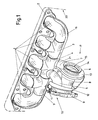
- the header pipe section 4 provides the connection between those formed from the parts 3 Exhaust collector and a turbine housing 17 ago.
- the manifold section 4 also ends the middle exhaust manifold 1 (but it could also be any other exhaust manifold, such as about one at the end of the exhaust manifold), while, as can be seen, in the axial direction is connected to a T exhaust pipe 3 each.
- At least part of this is advantageous Components of the exhaust manifold, preferably at least the collector pipe 4, at most also at least part of the T-exhaust pipes, made of deformed sheet metal, wherein Explosion deformation is conceivable as the deformation process, but preferably isostatic Pressing or hydraulic pressing (e.g. using hydraulic Pressure from the inside on a sheet in a corresponding shape).
- Another connection from the header pipe section 4 can go to a bypass duct 5, via the at least part of the exhaust gas of the internal combustion engine 20 via a by means of a lever 11 operated flap 10 (the arrow only shows the location of this flap an) can be fed to another user, such as the catalyst.
- the lever 11 is attached to a shaft mounted in a flange 9, to which Flange connects an outlet channel 8 or can be welded to it.
- a special socket as in the prior art for accommodating the flap at 10 and their actuation shaft with the lever 11 can be omitted.
- the turbine housing 17 is, as usual, approximately spiral-shaped, so as to remove the exhaust gas to a turbine located in the middle of the spiral (cf. 18 in FIGS. 3, 4). It surrounds in a conventional manner a rotor space 15 in which the turbine rotor 18 rotates (see Fig. 3, 4). As can be seen particularly from FIG. 1, the turbine housing settles 17 composed of a left spiral half 6 and a right spiral half 7, which Halves are welded together along the seam 19 visible in FIG. 1. Thereby a dense and less space-consuming unit is created than with a (also heavier) flange connection can be reached along the line 19 could. The bearing housing or the compressor housing can then be on the right housing half 7 of a turbocharger, which is driven by the turbine 18 becomes.
- a bearing housing flange 14 is used to connect these parts of a turbocharger provided that is welded to the right spiral half 7 or sealed in some other way can be connected.
- the left housing half 6, on the other hand, not only forms the half spiral, but also the known wheel contour of the turbine 18 (Fig. 3, 4) or the connection to an outlet channel 8, as is conventionally provided.
- This outlet duct 8 can preferably also consist of sheet metal and in a similar manner with the turbine housing 17 be connected, as will be explained later using the connection between Feed gas duct 21 and turbine housing 17 in connection with FIG. 3 or 4 is described.
- the weld seam 19 does not only extend over the spiral housing part of the turbine housing 17, but is extended so that it is in one piece also forms the feed gas duct 21 which is directly connected to the header pipe section 4, which reduces heat loss and makes production easier.
- a further sheet metal layer can be provided, like an end plate at 13 or at most a burst jacket. It is under the Invention quite possible, for example, to arrange four sheet metal layers one above the other. However, mixed forms are quite possible in which individual parts, such as the final part 13 or the bearing housing flange 14 discussed above are made of investment casting.
- Fig. 2 illustrates the structure described above and the associated parts in one exploded representation. 3 and in particular 4 should now be used with the help of Examples consisting of two sheet metal layers and at least one insulating layer be shown how these parts are assembled.
- the outside of the turbine housing 17 is made of the inner spiral part 6 made of sheet metal, for example from 0.5 to 1.5 mm, the outside of one stronger sheet metal jacket 22 is surrounded.
- the sheet metal jacket 22 has, for example a thickness in the range of 1.5 to 5 mm.
- the outer sheet metal jacket 22 can approximately may be 1.5 to 3 times as thick as the inner jacket 6. Between these Sheet metal layers is preferably a distance of at least 1 mm and preferably a maximum 8mm. For example, the distance is in the range of 2 to 5 mm.
- the outer sheet metal jacket can also be composed of two (spiral) halves be, of course, in any case, the production of more than two parts possible is.
- Both layers can be spaced apart by appropriately insulating spacers 23 are held apart, the spacer 23 shown in Fig. 3, the outlet channel 21 of the turbine housing 17 can surround a ring. in the one shown on the right in FIG. 3 End region of the sheet metal jacket 22 is pressed against the inner sheet (part 6) and welded to it, for example.
- At least one insulating layer can be provided between the two sheet metal layers 6, 22 become.
- a thin metal or sheet metal layer 26 may also be arranged between them can be, for example, reflective towards the radial interior is.
- the sheet metal layer 26 shown in FIG. 3 is only in the area of the feed channel 21 is provided, but can be in the entire space between the inner sheet metal layer 6 and the sheet metal jacket 22 can be provided. This is particularly advantageous if such an inner sheet metal layer 26 in the area of the volute around the turbine space is arranged because this ensures an even better burst protection.
- a branch 4 'of the header piece 4 (see FIG. 2) without welding with a mere plug connection connected, which forms a connecting pipeline.
- this connecting pipe 4 ' but possibly also the whole Collecting pipe piece 4, from an inner tube 27, an insulating layer 28 and a sheet metal jacket 29 is constructed.
- this sheet metal jacket 29 can also be made of something thicker Sheet metal exist, although no burst protection is required in this area.
- the one-piece design of the connecting pipeline 4 'with the header piece 4 is preferred, but within the scope of the present invention is not absolutely necessary.
- This nose piece 30 Between the inner sheet 27 and the sheet metal jacket 29 is an annular nose piece 30 clamped or welded to the sheet metal jacket 29.
- the left end (related to Fig. 3) of this nose piece 30 can be welded to the inner plate 27. But it is it is also possible to provide only one welding point, since this will suffice for one to avoid mutual displacement of the parts.
- This nose piece works with one conical expansion 32 at the end of the feed gas channel 21 together by putting it together with the expansion to support a snapped or by means of a (Not shown) screw contracted open clamping ring 31 is used secures the seat of the connecting pipe 4 'on the feed gas channel 21.
- FIG. 4 An even better heat transfer is obtained with an embodiment according to FIG. 4.
- This Embodiment differs from that of FIG. 3 in that the cone piece 32 'has a flatter angle ⁇ than in the previous embodiment.
- This Angle ⁇ should be a maximum of 30 °, preferably a maximum of 20 °, so that the inner Sheet 27 comes to rest frictionally and a heat transfer over a relatively large area.
- this angle ⁇ should not be too small, either Insertion of the inner tube sheet 27 should not be difficult, and should be at least 7 ° be.
- the cheapest version is advantageously such that the cone piece 32 'as Inlet funnel for the volute casing 17 is used and just widened so much that in an adjoining cylinder section 32 "the connecting pipeline 4 'under contact can be pushed onto the inner surface of the cylinder section 32 ′′ Tightness is achieved, and the length of the cylinder section 32 "becomes appropriate chosen so that the connecting pipe 4 'therein with thermal expansion and as a result of vibrations of the internal combustion engine can shift in it. It is understood that it would be theoretically possible, the confluence of the feed gas channel 21 without a cone transition to be designed so that the mentioned cylinder section 32 "on the connecting pipe 4 'comes to rest.
- FIG. 4 not only the connecting pipe 4 'of the header pipe 4 is shown, but the entire manifold section 4 in section.
- This has a central opening 33 for the connection of the neighboring parts 3 (see FIG. 1). Behind this opening 33 (in Fig. 4 right), the inner tube 27 narrows by an inner elbow tube inserted into it 34 to record, which is housed in an outer tube 35 and on the flange 2 (see Fig. 1) is welded.
- an outer one can do this too Sheet metal jacket 22 similar to FIG. 3 can be provided.
- this outer sheet metal jacket 22 is interrupted, is here preferably with the respective inner sheet metal parts 6, 27, 34 carried out a mere plug or slide connection, as explained above, which is easy to manufacture, whereas the sheet metal jacket 22 is welded over the entire length shown in FIG. 4, which of the outside is not a problem.
- the inner part 6, 27, 34 not gas-tight and there can be gas in the space between the inner and outer Sheet 22 get where it contributes to the insulation rather.
- too all other layers 24-26 which were described with reference to FIG. 3, also here Application.
- the sheet metal jacket 22 has over the largest part of the invention the connecting pipe 4 'combined housing 17 an approximately uniform distance from the inner sheet layer 6 or 33.
- This distance is about 1 mm and preferably amount to a maximum of 8mm, but will expediently be in the range of 2 to 5mm.
- a smaller one (see 32 ") or a larger distance (see at 21) may be advantageous.
Landscapes
- Engineering & Computer Science (AREA)
- Mechanical Engineering (AREA)
- General Engineering & Computer Science (AREA)
- Chemical & Material Sciences (AREA)
- Combustion & Propulsion (AREA)
- Chemical Kinetics & Catalysis (AREA)
- General Chemical & Material Sciences (AREA)
- Supercharger (AREA)
- Exhaust Silencers (AREA)
- Exhaust Gas After Treatment (AREA)
Priority Applications (3)
| Application Number | Priority Date | Filing Date | Title |
|---|---|---|---|
| EP02026895.9A EP1426557B1 (fr) | 2002-12-03 | 2002-12-03 | Boîtier pour turbocompresseur |
| JP2003390274A JP4530648B2 (ja) | 2002-12-03 | 2003-11-20 | ターボ過給機用ハウジング |
| US10/726,760 US7234302B2 (en) | 2002-12-03 | 2003-12-03 | Housing for a turbocharger |
Applications Claiming Priority (1)
| Application Number | Priority Date | Filing Date | Title |
|---|---|---|---|
| EP02026895.9A EP1426557B1 (fr) | 2002-12-03 | 2002-12-03 | Boîtier pour turbocompresseur |
Publications (2)
| Publication Number | Publication Date |
|---|---|
| EP1426557A1 true EP1426557A1 (fr) | 2004-06-09 |
| EP1426557B1 EP1426557B1 (fr) | 2013-07-17 |
Family
ID=32309361
Family Applications (1)
| Application Number | Title | Priority Date | Filing Date |
|---|---|---|---|
| EP02026895.9A Expired - Lifetime EP1426557B1 (fr) | 2002-12-03 | 2002-12-03 | Boîtier pour turbocompresseur |
Country Status (3)
| Country | Link |
|---|---|
| US (1) | US7234302B2 (fr) |
| EP (1) | EP1426557B1 (fr) |
| JP (1) | JP4530648B2 (fr) |
Cited By (25)
| Publication number | Priority date | Publication date | Assignee | Title |
|---|---|---|---|---|
| WO2006079732A1 (fr) * | 2005-01-31 | 2006-08-03 | Faurecia Systemes D'echappement | Element de ligne d'echappement equipe d'un turbocompresseur |
| FR2881471A1 (fr) * | 2005-01-31 | 2006-08-04 | Faurecia Sys Echappement | Element de ligne d'echappement equipe d'un turbocompresseur |
| EP1749686A1 (fr) * | 2005-08-06 | 2007-02-07 | Faurecia Abgastechnik GmbH | Système d'échappement pour véhicule automobile |
| WO2007104613A1 (fr) * | 2006-03-15 | 2007-09-20 | Robert Bosch Gmbh | Dispositif de charge avec un dispositif de mise a temperature des gaz d'echappement |
| WO2008125553A1 (fr) * | 2007-04-16 | 2008-10-23 | Napier Turbochargers Limited | Moteur à combustion interne |
| WO2008141927A1 (fr) * | 2007-05-24 | 2008-11-27 | Napier Turbochargers Limited | Turbocompresseur à gaz d'échappement comprenant un boîtier à double paroi |
| FR2924467A1 (fr) * | 2007-12-04 | 2009-06-05 | Renault Sas | Collecteur d'echappement avec turbocompresseur integre. |
| EP1914401A3 (fr) * | 2006-10-17 | 2009-07-29 | Friedrich Boysen GmbH & Co. KG | Collecteur de gaz d'échappement |
| EP2123881A1 (fr) * | 2008-05-23 | 2009-11-25 | Gerhard Schmitz | Moteur à combustion interne suralimente par turbo-compresseur |
| US7836692B2 (en) | 2005-01-31 | 2010-11-23 | Faurecia Systemes D'echappement | Exhaust line element provided with a turbocompressor |
| DE102009030015A1 (de) * | 2009-06-23 | 2010-12-30 | Bayerische Motoren Werke Aktiengesellschaft | Mehrteiliger Abgaskrümmer |
| US20110016859A1 (en) * | 2008-03-13 | 2011-01-27 | Borgwarner Inc. | Exhaust manifold of an internal combustion engine |
| DE102009030482A1 (de) * | 2009-06-24 | 2011-03-24 | Benteler Automobiltechnik Gmbh | Abgasbaugruppe |
| DE102011121294A1 (de) | 2011-12-15 | 2012-07-12 | Daimler Ag | Abgassammler |
| DE102012110707A1 (de) * | 2012-11-08 | 2014-05-08 | Benteler Automobiltechnik Gmbh | Abgasturboladerbaugruppe mit integrierter Isolierlage |
| DE102009016266B4 (de) | 2009-04-03 | 2014-08-21 | Audi Ag | Abgaskrümmer |
| DE102013213850A1 (de) * | 2013-07-16 | 2015-01-22 | Bayerische Motoren Werke Aktiengesellschaft | Anordnung zum fluidleitenden Verbinden eines Gehäuses eines Abgasturboladers mit einem weiteren abgasführenden Bauteil |
| CN104329155A (zh) * | 2014-11-19 | 2015-02-04 | 柳州市莫尔斯汽配制造有限公司 | 汽车排气管结构 |
| CN104870769A (zh) * | 2012-12-26 | 2015-08-26 | 雷诺股份公司 | 用于内燃发动机的排气构件 |
| WO2017064557A1 (fr) * | 2015-10-12 | 2017-04-20 | Angelo Miretti | Moteur ayant un dispositif de protection contre les explosions |
| CN106640314A (zh) * | 2016-12-30 | 2017-05-10 | 中国第汽车股份有限公司 | 多段式排气管结构 |
| WO2017085353A1 (fr) * | 2015-11-18 | 2017-05-26 | Wärtsilä Finland Oy | Structure d'isolation thermique |
| EP3112633A4 (fr) * | 2014-02-28 | 2017-12-13 | Mitsubishi Heavy Industries, Ltd. | Carter de turbine en tôle |
| US10436069B2 (en) | 2017-01-30 | 2019-10-08 | Garrett Transportation I Inc. | Sheet metal turbine housing with biaxial volute configuration |
| WO2020003096A1 (fr) * | 2018-06-26 | 2020-01-02 | 3M Innovative Properties Company | Élément de feuille d'isolation thermique, trajet d'introduction de gaz d'échappement et turbocompresseur |
Families Citing this family (40)
| Publication number | Priority date | Publication date | Assignee | Title |
|---|---|---|---|---|
| DE10254859A1 (de) * | 2002-11-25 | 2004-06-03 | Mann + Hummel Gmbh | Turbolader |
| EP1541826B1 (fr) * | 2003-12-13 | 2007-03-14 | Ford Global Technologies, LLC | Turbocompresseur |
| JP4512058B2 (ja) * | 2006-04-04 | 2010-07-28 | トヨタ自動車株式会社 | タービンハウジング |
| US20080066465A1 (en) * | 2006-09-20 | 2008-03-20 | Francis Andrew Maidens | Turbocharger header for an internal combustion engine |
| DE502008000749D1 (de) * | 2007-03-27 | 2010-07-15 | Abb Turbo Systems Ag | Gehäuseisolation |
| DE102008031887A1 (de) * | 2008-07-08 | 2010-03-04 | J. Eberspächer GmbH & Co. KG | Abgasanlage |
| US8206133B2 (en) * | 2008-08-12 | 2012-06-26 | GM Global Technology Operations LLC | Turbocharger housing with integral inlet and outlet openings |
| CN102149906B (zh) * | 2008-08-14 | 2014-10-01 | 柔性金属有限公司 | 改进的排气歧管到壳体的连接结构 |
| DE102008047448B4 (de) * | 2008-09-16 | 2020-09-24 | Bayerische Motoren Werke Aktiengesellschaft | Abgasturbolader |
| US20110252775A1 (en) * | 2008-10-01 | 2011-10-20 | Borgwarner Inc. | Exhaust flow insulator for an exhaust system device |
| AT507825B1 (de) * | 2009-02-03 | 2011-02-15 | Ge Jenbacher Gmbh & Co Ohg | Stationäre brennkraftmaschine |
| DE102009011379B4 (de) * | 2009-03-05 | 2012-07-05 | Benteler Automobiltechnik Gmbh | Abgasbaugruppe |
| KR20160055282A (ko) * | 2009-10-30 | 2016-05-17 | 보르그워너 인코퍼레이티드 | 배기가스 터보차저의 터빈 케이싱 |
| DE102010005761A1 (de) * | 2010-01-25 | 2011-07-28 | Benteler Automobiltechnik GmbH, 33102 | Abgasbaugruppe |
| DE102010026958A1 (de) * | 2010-07-12 | 2012-01-12 | J. Eberspächer GmbH & Co. KG | Flanschplatte, Flanschverbindung und Abgaskrümmer |
| US9732631B2 (en) * | 2010-10-25 | 2017-08-15 | Borgwarner Inc. | Exhaust-gas turbocharger |
| US9500120B2 (en) | 2011-03-14 | 2016-11-22 | Flexible Metal, Inc. | Integration ring |
| JP5338991B1 (ja) * | 2011-11-02 | 2013-11-13 | トヨタ自動車株式会社 | タービンハウジング及び排気タービン過給機 |
| KR20140110048A (ko) * | 2012-01-17 | 2014-09-16 | 보르그워너 인코퍼레이티드 | 배기 터보차저 |
| JP2013213491A (ja) * | 2012-03-08 | 2013-10-17 | Calsonic Kansei Corp | 二重管式エキゾースト・マニホールド |
| JP6072299B2 (ja) | 2013-12-04 | 2017-02-01 | 三菱重工業株式会社 | 板金タービンハウジング |
| DE102014105053B4 (de) * | 2014-04-09 | 2021-06-24 | Dr. Ing. H.C. F. Porsche Aktiengesellschaft | Abgasanlage eines Kraftfahrzeugs und Kraftfahrzeug |
| US9945258B2 (en) | 2014-10-10 | 2018-04-17 | Ford Global Technologies, Llc | Sheet metal turbine housing with cellular structure reinforcement |
| US9874136B2 (en) * | 2014-12-23 | 2018-01-23 | Caterpillar Inc. | Exhaust outlet elbow bolt pattern |
| JP6249030B2 (ja) * | 2016-03-14 | 2017-12-20 | マツダ株式会社 | ターボ過給機付エンジン |
| DE102016212249B4 (de) * | 2016-07-05 | 2024-05-02 | Ford Global Technologies, Llc | Zweistufig aufladbare direkteinspritzende Brennkraftmaschine mit Abgasnachbehandlung und Verfahren zum Betreiben einer derartigen Brennkraftmaschine |
| US10494955B2 (en) | 2017-01-30 | 2019-12-03 | Garrett Transportation I Inc. | Sheet metal turbine housing with containment dampers |
| US10472988B2 (en) | 2017-01-30 | 2019-11-12 | Garrett Transportation I Inc. | Sheet metal turbine housing and related turbocharger systems |
| US10544703B2 (en) | 2017-01-30 | 2020-01-28 | Garrett Transportation I Inc. | Sheet metal turbine housing with cast core |
| WO2018179328A1 (fr) * | 2017-03-31 | 2018-10-04 | 三菱重工エンジン&ターボチャージャ株式会社 | Logement de turbine et turbocompresseur équipé de celui-ci |
| US10690144B2 (en) | 2017-06-27 | 2020-06-23 | Garrett Transportation I Inc. | Compressor housings and fabrication methods |
| US11255248B2 (en) | 2017-08-15 | 2022-02-22 | Arctic Cat Inc. | Snowmobile having a parallel-path exhaust system for two-stroke engine |
| CA3014123A1 (fr) | 2017-08-15 | 2019-02-15 | Arctic Cat Inc. | Systeme d'huile sous pression alimente par un moteur deux-temps |
| DE102018101066A1 (de) * | 2018-01-18 | 2019-07-18 | Man Energy Solutions Se | Berstschutzvorrichtung für eine Gasturbomaschine |
| DE102018101635A1 (de) * | 2018-01-25 | 2019-07-25 | Man Energy Solutions Se | Turbolader |
| JP2019199853A (ja) * | 2018-05-18 | 2019-11-21 | カルソニックカンセイ株式会社 | タービンハウジング |
| JP7084543B2 (ja) * | 2019-02-25 | 2022-06-14 | 三菱重工エンジン&ターボチャージャ株式会社 | タービンハウジングおよびターボチャージャ |
| JP7099625B2 (ja) * | 2019-04-17 | 2022-07-12 | 株式会社Ihi | タービンハウジングおよび過給機 |
| US11421577B2 (en) * | 2020-02-25 | 2022-08-23 | Divergent Technologies, Inc. | Exhaust headers with integrated heat shielding and thermal syphoning |
| US11732729B2 (en) | 2021-01-26 | 2023-08-22 | Garrett Transportation I Inc | Sheet metal turbine housing |
Citations (2)
| Publication number | Priority date | Publication date | Assignee | Title |
|---|---|---|---|---|
| EP0671551A1 (fr) * | 1994-03-09 | 1995-09-13 | Etablissement STREIT S.A. | Collecteur d'échappement pour moteur de véhicules automobiles |
| DE10022052A1 (de) * | 1999-05-26 | 2001-03-01 | Gillet Heinrich Gmbh | Turbinengehäuse für Abgasturbolader |
Family Cites Families (29)
| Publication number | Priority date | Publication date | Assignee | Title |
|---|---|---|---|---|
| US2423462A (en) * | 1943-05-04 | 1947-07-08 | Mercier Pierre Ernest | Flexible coupling for exhaust conduits of internal-combustion engines |
| US2529880A (en) * | 1949-03-15 | 1950-11-14 | Elliott Co | Turboexpander |
| US3068638A (en) * | 1953-06-09 | 1962-12-18 | Laval Steam Turbine Inc De | Turbocharger for internal com. bustion engines |
| US3310940A (en) * | 1965-10-07 | 1967-03-28 | Stalker Corp | Gas turbines |
| GB1199158A (en) * | 1966-11-25 | 1970-07-15 | Cav Ltd | Casings for Radial Flow Fluid Turbines e.g. of Turbo-Superchargers for I.C. Engines |
| GB1263932A (en) * | 1969-06-27 | 1972-02-16 | Cav Ltd | Turbo superchargers |
| DE2252705A1 (de) * | 1972-10-27 | 1974-05-02 | Daimler Benz Ag | Anbau eines abgasturboladers an eine brennkraftmaschine |
| AT365307B (de) * | 1976-12-10 | 1982-01-11 | List Hans | Brennkraftmaschine mit von einem geblaese durchluefteter schalldaemmender kapsel |
| FR2378178A1 (fr) * | 1977-01-24 | 1978-08-18 | Semt | Procede et dispositif d'amenagement de l'ecoulement des gaz dans un collecteur d'echappement d'un moteur a combustion interne |
| US4182122A (en) * | 1978-02-15 | 1980-01-08 | Caterpillar Tractor Co. | Insulated exhaust manifold |
| JPS54129221A (en) * | 1978-03-31 | 1979-10-06 | Nissan Motor Co Ltd | Internal combustion engine exhaust turbo supercharger |
| JPS5537508A (en) * | 1978-09-06 | 1980-03-15 | Ishikawajima Harima Heavy Ind Co Ltd | Turbine casing for superchrger |
| DE3334413A1 (de) * | 1982-09-24 | 1984-03-29 | Witzenmann GmbH, Metallschlauch-Fabrik Pforzheim, 7530 Pforzheim | Auspuffsammelleitung fuer mehrzylindrische kraftfahrzeugmotoren |
| US4689952A (en) * | 1986-06-13 | 1987-09-01 | Arvin Industries, Inc. | Tuned exhaust manifold |
| AT395637B (de) * | 1987-05-14 | 1993-02-25 | Steyr Daimler Puch Ag | Abgaseinrichtung fuer mehrzylinder-brennkraftmaschinen |
| DE3721608A1 (de) * | 1987-06-30 | 1989-01-12 | Klifa Gmbh & Co | Auspuff-sammelrohr |
| JPH05240193A (ja) * | 1992-02-29 | 1993-09-17 | Hideo Yoshikawa | 流体機器の騒音低減構造 |
| DE4342572C1 (de) * | 1993-12-14 | 1994-11-24 | Mtu Friedrichshafen Gmbh | Abgasanlage für eine aufgeladene Brennkraftmaschine |
| JPH0893977A (ja) * | 1994-09-28 | 1996-04-12 | Sango Co Ltd | 管継手 |
| US5816043A (en) * | 1996-01-02 | 1998-10-06 | Acoust-A-Fiber Research And Development, Inc. | Shield encompassing a hot pipe |
| DE59701049D1 (de) * | 1996-06-20 | 2000-02-24 | Etis Ag Teufen | Isolierung für bauteile mit dreidimensionalen aussenflächen |
| JPH1089063A (ja) * | 1996-09-10 | 1998-04-07 | Honda Motor Co Ltd | 多気筒内燃機関の排気マニホールド |
| JP2002054447A (ja) * | 2000-08-09 | 2002-02-20 | Aisin Takaoka Ltd | タービンハウジング |
| US6474092B2 (en) * | 2001-01-26 | 2002-11-05 | Il Yoo Davis | Apparatus and method for a blower cover |
| US6797402B2 (en) * | 2001-09-28 | 2004-09-28 | Dana Corporation | Insulated heat shield with waved edge |
| US6647715B2 (en) * | 2001-11-30 | 2003-11-18 | Van-Rob Stampings Inc. | Heat shield for an exhaust system of an internal combustion engine |
| DE10336978B3 (de) * | 2003-08-12 | 2005-01-13 | Mtu Friedrichshafen Gmbh | Trägergehäuse für einen oder mehrere Abgasturbolader einer Brennkraftmaschine |
| EP1541826B1 (fr) * | 2003-12-13 | 2007-03-14 | Ford Global Technologies, LLC | Turbocompresseur |
| DE10360645A1 (de) * | 2003-12-23 | 2005-07-21 | Daimlerchrysler Ag | Auspuffkrümmer |
-
2002
- 2002-12-03 EP EP02026895.9A patent/EP1426557B1/fr not_active Expired - Lifetime
-
2003
- 2003-11-20 JP JP2003390274A patent/JP4530648B2/ja not_active Expired - Lifetime
- 2003-12-03 US US10/726,760 patent/US7234302B2/en not_active Expired - Lifetime
Patent Citations (2)
| Publication number | Priority date | Publication date | Assignee | Title |
|---|---|---|---|---|
| EP0671551A1 (fr) * | 1994-03-09 | 1995-09-13 | Etablissement STREIT S.A. | Collecteur d'échappement pour moteur de véhicules automobiles |
| DE10022052A1 (de) * | 1999-05-26 | 2001-03-01 | Gillet Heinrich Gmbh | Turbinengehäuse für Abgasturbolader |
Cited By (37)
| Publication number | Priority date | Publication date | Assignee | Title |
|---|---|---|---|---|
| DE112006000304B4 (de) * | 2005-01-31 | 2015-01-08 | Faurecia Systemes D'echappement | Element einer Abgasleitung mit einem Turbokompressor |
| FR2881471A1 (fr) * | 2005-01-31 | 2006-08-04 | Faurecia Sys Echappement | Element de ligne d'echappement equipe d'un turbocompresseur |
| FR2881470A1 (fr) * | 2005-01-31 | 2006-08-04 | Faurecia Sys Echappement | Element de ligne d'echappement equipe d'un turbocompresseur. |
| WO2006079732A1 (fr) * | 2005-01-31 | 2006-08-03 | Faurecia Systemes D'echappement | Element de ligne d'echappement equipe d'un turbocompresseur |
| US7836692B2 (en) | 2005-01-31 | 2010-11-23 | Faurecia Systemes D'echappement | Exhaust line element provided with a turbocompressor |
| EP1749686A1 (fr) * | 2005-08-06 | 2007-02-07 | Faurecia Abgastechnik GmbH | Système d'échappement pour véhicule automobile |
| WO2007104613A1 (fr) * | 2006-03-15 | 2007-09-20 | Robert Bosch Gmbh | Dispositif de charge avec un dispositif de mise a temperature des gaz d'echappement |
| US8365519B2 (en) | 2006-03-15 | 2013-02-05 | Robert Bosch Gmbh | Charging device with exhaust gas temperature control device |
| EP1914401A3 (fr) * | 2006-10-17 | 2009-07-29 | Friedrich Boysen GmbH & Co. KG | Collecteur de gaz d'échappement |
| WO2008125553A1 (fr) * | 2007-04-16 | 2008-10-23 | Napier Turbochargers Limited | Moteur à combustion interne |
| WO2008141927A1 (fr) * | 2007-05-24 | 2008-11-27 | Napier Turbochargers Limited | Turbocompresseur à gaz d'échappement comprenant un boîtier à double paroi |
| FR2924467A1 (fr) * | 2007-12-04 | 2009-06-05 | Renault Sas | Collecteur d'echappement avec turbocompresseur integre. |
| US9151208B2 (en) * | 2008-03-13 | 2015-10-06 | Borgwarner Inc. | Exhaust manifold of an internal combustion engine |
| US20110016859A1 (en) * | 2008-03-13 | 2011-01-27 | Borgwarner Inc. | Exhaust manifold of an internal combustion engine |
| DE112009000420T5 (de) | 2008-03-13 | 2011-02-10 | Borgwarner Inc., Auburn Hills | Auspuffkrümmer eines Verbrennungsmotors |
| US8087243B2 (en) | 2008-05-23 | 2012-01-03 | Gerhard Schmitz | Internal combustion engine turbocharged by a turbocharger |
| BE1018159A5 (fr) * | 2008-05-23 | 2010-06-01 | Gerhard Schmitz | Moteur a combustion interne suralimente par turbo-compresseur. |
| EP2123881A1 (fr) * | 2008-05-23 | 2009-11-25 | Gerhard Schmitz | Moteur à combustion interne suralimente par turbo-compresseur |
| DE102009016266B4 (de) | 2009-04-03 | 2014-08-21 | Audi Ag | Abgaskrümmer |
| DE102009030015A1 (de) * | 2009-06-23 | 2010-12-30 | Bayerische Motoren Werke Aktiengesellschaft | Mehrteiliger Abgaskrümmer |
| US8312721B2 (en) | 2009-06-24 | 2012-11-20 | Benteler Automobiltechnik Gmbh | Exhaust gas assembly |
| DE102009030482A1 (de) * | 2009-06-24 | 2011-03-24 | Benteler Automobiltechnik Gmbh | Abgasbaugruppe |
| DE102011121294A1 (de) | 2011-12-15 | 2012-07-12 | Daimler Ag | Abgassammler |
| DE102012110707A1 (de) * | 2012-11-08 | 2014-05-08 | Benteler Automobiltechnik Gmbh | Abgasturboladerbaugruppe mit integrierter Isolierlage |
| DE102012110707B4 (de) * | 2012-11-08 | 2015-11-19 | Benteler Automobiltechnik Gmbh | Abgasturboladerbaugruppe mit integrierter Isolierlage |
| CN104870769A (zh) * | 2012-12-26 | 2015-08-26 | 雷诺股份公司 | 用于内燃发动机的排气构件 |
| DE102013213850B4 (de) * | 2013-07-16 | 2015-11-19 | Bayerische Motoren Werke Aktiengesellschaft | Anordnung zum fluidleitenden Verbinden eines Gehäuses eines Abgasturboladers mit einem weiteren abgasführenden Bauteil |
| DE102013213850A1 (de) * | 2013-07-16 | 2015-01-22 | Bayerische Motoren Werke Aktiengesellschaft | Anordnung zum fluidleitenden Verbinden eines Gehäuses eines Abgasturboladers mit einem weiteren abgasführenden Bauteil |
| US10400617B2 (en) | 2014-02-28 | 2019-09-03 | Mitsubishi Heavy Industries Engine & Turbocharger, Ltd. | Sheet-metal turbine housing |
| EP3112633A4 (fr) * | 2014-02-28 | 2017-12-13 | Mitsubishi Heavy Industries, Ltd. | Carter de turbine en tôle |
| CN104329155A (zh) * | 2014-11-19 | 2015-02-04 | 柳州市莫尔斯汽配制造有限公司 | 汽车排气管结构 |
| WO2017064557A1 (fr) * | 2015-10-12 | 2017-04-20 | Angelo Miretti | Moteur ayant un dispositif de protection contre les explosions |
| WO2017085353A1 (fr) * | 2015-11-18 | 2017-05-26 | Wärtsilä Finland Oy | Structure d'isolation thermique |
| US10519844B2 (en) | 2015-11-18 | 2019-12-31 | Wärtsilä Finland Oy | Heat insulation structure |
| CN106640314A (zh) * | 2016-12-30 | 2017-05-10 | 中国第汽车股份有限公司 | 多段式排气管结构 |
| US10436069B2 (en) | 2017-01-30 | 2019-10-08 | Garrett Transportation I Inc. | Sheet metal turbine housing with biaxial volute configuration |
| WO2020003096A1 (fr) * | 2018-06-26 | 2020-01-02 | 3M Innovative Properties Company | Élément de feuille d'isolation thermique, trajet d'introduction de gaz d'échappement et turbocompresseur |
Also Published As
| Publication number | Publication date |
|---|---|
| JP2004183651A (ja) | 2004-07-02 |
| JP4530648B2 (ja) | 2010-08-25 |
| EP1426557B1 (fr) | 2013-07-17 |
| US20040109759A1 (en) | 2004-06-10 |
| US7234302B2 (en) | 2007-06-26 |
Similar Documents
| Publication | Publication Date | Title |
|---|---|---|
| EP1426557B1 (fr) | Boîtier pour turbocompresseur | |
| DE10061846B4 (de) | Abgasturbolader für eine Brennkraftmaschine | |
| EP1213538B1 (fr) | Dispositif pour gaz d'échappement comprenant un résonateur de Helmholtz | |
| EP0856648B1 (fr) | Elément de conduite flexible pour conduites de gaz d'échappement | |
| EP1206631B1 (fr) | Collecteur de gaz d'echappement | |
| DE29909018U1 (de) | Turbinengehäuse für Abgasturbolader | |
| DE102009024718A1 (de) | Abgasbehandlungsvorrichtung für den motornahen Einsatz | |
| DE10307028B3 (de) | Anordnung zur Überführung der Abgase eines Verbrennungsmotors in eine Abgasleitung | |
| DE112014002067T5 (de) | Turbinengehäuse eines Abgasturboladers | |
| DE19819946A1 (de) | Abgaskrümmer | |
| EP1785602B1 (fr) | Silencieux | |
| EP3009623B1 (fr) | Composant pour une installation de gaz d'échappement et fixation pour ce composant | |
| EP2757234B1 (fr) | Silencieux et son procédé de fabrication | |
| EP2369895A2 (fr) | Elément de chauffage électrique | |
| EP1899654B1 (fr) | Chaudière de chauffage | |
| DE112007000864B4 (de) | Abgaskrümmer-Anordnung | |
| DE10348141B3 (de) | Innerer Wärmeübertrager für Hochdruckkältemittel mit Akkumulator | |
| DE102004018693B4 (de) | Abgasanlage | |
| DE202007004757U1 (de) | Entkoppelelement mit Isolation | |
| EP3252284A1 (fr) | Moteur à combustion interne comprenant deux turbocompresseurs | |
| EP3828396B1 (fr) | Silencieux de gaz d'échappement | |
| EP1225313B1 (fr) | Dispositif de traitement des gaz d'échappement | |
| EP0693616A1 (fr) | Dispositif pour la purification ou la décomposition de gaz d'échappement chauds | |
| EP1260262A2 (fr) | Dispositif de chauffage pour élément filtrant d'un filtre à particules et filtre à particules | |
| DE102008050961B4 (de) | Abgaskrümmeranordnung |
Legal Events
| Date | Code | Title | Description |
|---|---|---|---|
| PUAI | Public reference made under article 153(3) epc to a published international application that has entered the european phase |
Free format text: ORIGINAL CODE: 0009012 |
|
| AK | Designated contracting states |
Kind code of ref document: A1 Designated state(s): AT BE BG CH CY CZ DE DK EE ES FI FR GB GR IE IT LI LU MC NL PT SE SI SK TR |
|
| AX | Request for extension of the european patent |
Extension state: AL LT LV MK RO |
|
| 17P | Request for examination filed |
Effective date: 20040714 |
|
| AKX | Designation fees paid |
Designated state(s): DE FR GB IT NL SE |
|
| RAP1 | Party data changed (applicant data changed or rights of an application transferred) |
Owner name: BORGWARNER INC. |
|
| 17Q | First examination report despatched |
Effective date: 20080428 |
|
| APBK | Appeal reference recorded |
Free format text: ORIGINAL CODE: EPIDOSNREFNE |
|
| APBN | Date of receipt of notice of appeal recorded |
Free format text: ORIGINAL CODE: EPIDOSNNOA2E |
|
| APBR | Date of receipt of statement of grounds of appeal recorded |
Free format text: ORIGINAL CODE: EPIDOSNNOA3E |
|
| APAF | Appeal reference modified |
Free format text: ORIGINAL CODE: EPIDOSCREFNE |
|
| APBT | Appeal procedure closed |
Free format text: ORIGINAL CODE: EPIDOSNNOA9E |
|
| REG | Reference to a national code |
Ref country code: DE Ref legal event code: R079 Ref document number: 50215804 Country of ref document: DE Free format text: PREVIOUS MAIN CLASS: F01D0009020000 Ipc: F02B0067100000 |
|
| GRAP | Despatch of communication of intention to grant a patent |
Free format text: ORIGINAL CODE: EPIDOSNIGR1 |
|
| RIC1 | Information provided on ipc code assigned before grant |
Ipc: F01D 25/26 20060101ALI20130124BHEP Ipc: F01D 9/02 20060101ALI20130124BHEP Ipc: F04D 29/60 20060101ALI20130124BHEP Ipc: F02B 39/00 20060101ALI20130124BHEP Ipc: F01D 25/24 20060101ALI20130124BHEP Ipc: F04D 29/42 20060101ALI20130124BHEP Ipc: F02B 67/10 20060101AFI20130124BHEP Ipc: F01N 13/10 20100101ALI20130124BHEP Ipc: F02C 6/12 20060101ALI20130124BHEP |
|
| GRAS | Grant fee paid |
Free format text: ORIGINAL CODE: EPIDOSNIGR3 |
|
| GRAA | (expected) grant |
Free format text: ORIGINAL CODE: 0009210 |
|
| AK | Designated contracting states |
Kind code of ref document: B1 Designated state(s): DE FR GB IT NL SE |
|
| REG | Reference to a national code |
Ref country code: GB Ref legal event code: FG4D Free format text: NOT ENGLISH |
|
| REG | Reference to a national code |
Ref country code: DE Ref legal event code: R096 Ref document number: 50215804 Country of ref document: DE Effective date: 20130912 |
|
| REG | Reference to a national code |
Ref country code: SE Ref legal event code: TRGR |
|
| REG | Reference to a national code |
Ref country code: NL Ref legal event code: T3 |
|
| PLBE | No opposition filed within time limit |
Free format text: ORIGINAL CODE: 0009261 |
|
| STAA | Information on the status of an ep patent application or granted ep patent |
Free format text: STATUS: NO OPPOSITION FILED WITHIN TIME LIMIT |
|
| 26N | No opposition filed |
Effective date: 20140422 |
|
| REG | Reference to a national code |
Ref country code: DE Ref legal event code: R097 Ref document number: 50215804 Country of ref document: DE Effective date: 20140422 |
|
| REG | Reference to a national code |
Ref country code: FR Ref legal event code: PLFP Year of fee payment: 14 |
|
| REG | Reference to a national code |
Ref country code: FR Ref legal event code: PLFP Year of fee payment: 15 |
|
| REG | Reference to a national code |
Ref country code: FR Ref legal event code: PLFP Year of fee payment: 16 |
|
| PGFP | Annual fee paid to national office [announced via postgrant information from national office to epo] |
Ref country code: NL Payment date: 20201116 Year of fee payment: 19 |
|
| PGFP | Annual fee paid to national office [announced via postgrant information from national office to epo] |
Ref country code: DE Payment date: 20201112 Year of fee payment: 19 Ref country code: FR Payment date: 20201119 Year of fee payment: 19 Ref country code: SE Payment date: 20201208 Year of fee payment: 19 Ref country code: GB Payment date: 20201130 Year of fee payment: 19 |
|
| PGFP | Annual fee paid to national office [announced via postgrant information from national office to epo] |
Ref country code: IT Payment date: 20201218 Year of fee payment: 19 |
|
| REG | Reference to a national code |
Ref country code: DE Ref legal event code: R119 Ref document number: 50215804 Country of ref document: DE |
|
| REG | Reference to a national code |
Ref country code: SE Ref legal event code: EUG |
|
| REG | Reference to a national code |
Ref country code: NL Ref legal event code: MM Effective date: 20220101 |
|
| GBPC | Gb: european patent ceased through non-payment of renewal fee |
Effective date: 20211203 |
|
| PG25 | Lapsed in a contracting state [announced via postgrant information from national office to epo] |
Ref country code: NL Free format text: LAPSE BECAUSE OF NON-PAYMENT OF DUE FEES Effective date: 20220101 |
|
| PG25 | Lapsed in a contracting state [announced via postgrant information from national office to epo] |
Ref country code: SE Free format text: LAPSE BECAUSE OF NON-PAYMENT OF DUE FEES Effective date: 20211204 Ref country code: GB Free format text: LAPSE BECAUSE OF NON-PAYMENT OF DUE FEES Effective date: 20211203 Ref country code: DE Free format text: LAPSE BECAUSE OF NON-PAYMENT OF DUE FEES Effective date: 20220701 |
|
| PG25 | Lapsed in a contracting state [announced via postgrant information from national office to epo] |
Ref country code: FR Free format text: LAPSE BECAUSE OF NON-PAYMENT OF DUE FEES Effective date: 20211231 |
|
| PG25 | Lapsed in a contracting state [announced via postgrant information from national office to epo] |
Ref country code: IT Free format text: LAPSE BECAUSE OF NON-PAYMENT OF DUE FEES Effective date: 20211203 |