EP1426578A1 - Procédé pour tester les turbocompresseurs - Google Patents
Procédé pour tester les turbocompresseurs Download PDFInfo
- Publication number
- EP1426578A1 EP1426578A1 EP03025937A EP03025937A EP1426578A1 EP 1426578 A1 EP1426578 A1 EP 1426578A1 EP 03025937 A EP03025937 A EP 03025937A EP 03025937 A EP03025937 A EP 03025937A EP 1426578 A1 EP1426578 A1 EP 1426578A1
- Authority
- EP
- European Patent Office
- Prior art keywords
- exhaust gas
- gas turbocharger
- combustion engine
- internal combustion
- air
- Prior art date
- Legal status (The legal status is an assumption and is not a legal conclusion. Google has not performed a legal analysis and makes no representation as to the accuracy of the status listed.)
- Granted
Links
- 238000012360 testing method Methods 0.000 title claims abstract description 56
- 238000000034 method Methods 0.000 title claims abstract description 27
- 238000002485 combustion reaction Methods 0.000 claims abstract description 61
- 238000005259 measurement Methods 0.000 claims abstract description 5
- 230000006835 compression Effects 0.000 claims description 3
- 238000007906 compression Methods 0.000 claims description 3
- 239000003570 air Substances 0.000 description 70
- 239000012080 ambient air Substances 0.000 description 5
- 230000001360 synchronised effect Effects 0.000 description 2
- 238000009825 accumulation Methods 0.000 description 1
- 238000010586 diagram Methods 0.000 description 1
- 238000004519 manufacturing process Methods 0.000 description 1
Images
Classifications
-
- F—MECHANICAL ENGINEERING; LIGHTING; HEATING; WEAPONS; BLASTING
- F02—COMBUSTION ENGINES; HOT-GAS OR COMBUSTION-PRODUCT ENGINE PLANTS
- F02D—CONTROLLING COMBUSTION ENGINES
- F02D41/00—Electrical control of supply of combustible mixture or its constituents
- F02D41/0002—Controlling intake air
- F02D41/0007—Controlling intake air for control of turbo-charged or super-charged engines
-
- F—MECHANICAL ENGINEERING; LIGHTING; HEATING; WEAPONS; BLASTING
- F02—COMBUSTION ENGINES; HOT-GAS OR COMBUSTION-PRODUCT ENGINE PLANTS
- F02B—INTERNAL-COMBUSTION PISTON ENGINES; COMBUSTION ENGINES IN GENERAL
- F02B37/00—Engines characterised by provision of pumps driven at least for part of the time by exhaust
-
- F—MECHANICAL ENGINEERING; LIGHTING; HEATING; WEAPONS; BLASTING
- F02—COMBUSTION ENGINES; HOT-GAS OR COMBUSTION-PRODUCT ENGINE PLANTS
- F02B—INTERNAL-COMBUSTION PISTON ENGINES; COMBUSTION ENGINES IN GENERAL
- F02B37/00—Engines characterised by provision of pumps driven at least for part of the time by exhaust
- F02B37/04—Engines with exhaust drive and other drive of pumps, e.g. with exhaust-driven pump and mechanically-driven second pump
- F02B37/10—Engines with exhaust drive and other drive of pumps, e.g. with exhaust-driven pump and mechanically-driven second pump at least one pump being alternatively or simultaneously driven by exhaust and other drive, e.g. by pressurised fluid from a reservoir or an engine-driven pump
-
- F—MECHANICAL ENGINEERING; LIGHTING; HEATING; WEAPONS; BLASTING
- F02—COMBUSTION ENGINES; HOT-GAS OR COMBUSTION-PRODUCT ENGINE PLANTS
- F02B—INTERNAL-COMBUSTION PISTON ENGINES; COMBUSTION ENGINES IN GENERAL
- F02B37/00—Engines characterised by provision of pumps driven at least for part of the time by exhaust
- F02B37/12—Control of the pumps
-
- F—MECHANICAL ENGINEERING; LIGHTING; HEATING; WEAPONS; BLASTING
- F02—COMBUSTION ENGINES; HOT-GAS OR COMBUSTION-PRODUCT ENGINE PLANTS
- F02D—CONTROLLING COMBUSTION ENGINES
- F02D2200/00—Input parameters for engine control
- F02D2200/02—Input parameters for engine control the parameters being related to the engine
- F02D2200/04—Engine intake system parameters
- F02D2200/0414—Air temperature
-
- F—MECHANICAL ENGINEERING; LIGHTING; HEATING; WEAPONS; BLASTING
- F02—COMBUSTION ENGINES; HOT-GAS OR COMBUSTION-PRODUCT ENGINE PLANTS
- F02D—CONTROLLING COMBUSTION ENGINES
- F02D41/00—Electrical control of supply of combustible mixture or its constituents
- F02D41/02—Circuit arrangements for generating control signals
- F02D41/18—Circuit arrangements for generating control signals by measuring intake air flow
- F02D41/187—Circuit arrangements for generating control signals by measuring intake air flow using a hot wire flow sensor
-
- Y—GENERAL TAGGING OF NEW TECHNOLOGICAL DEVELOPMENTS; GENERAL TAGGING OF CROSS-SECTIONAL TECHNOLOGIES SPANNING OVER SEVERAL SECTIONS OF THE IPC; TECHNICAL SUBJECTS COVERED BY FORMER USPC CROSS-REFERENCE ART COLLECTIONS [XRACs] AND DIGESTS
- Y02—TECHNOLOGIES OR APPLICATIONS FOR MITIGATION OR ADAPTATION AGAINST CLIMATE CHANGE
- Y02T—CLIMATE CHANGE MITIGATION TECHNOLOGIES RELATED TO TRANSPORTATION
- Y02T10/00—Road transport of goods or passengers
- Y02T10/10—Internal combustion engine [ICE] based vehicles
- Y02T10/12—Improving ICE efficiencies
Definitions
- the invention relates to a method for testing turbochargers according to the preamble of claim 1 or 5.
- the turbine of the exhaust gas turbocharger not hotter To operate combustion air of an internal combustion engine, but with ambient temperature having compressed air.
- the exhaust gas turbocharger is not under load to consider. As a result, practically only a mechanical running test can take place.
- There in the known cold test of the exhaust gas turbocharger are not operated in the turbo map can not be determined its performance and operating characteristics.
- each cylinder bank is associated with an exhaust gas turbocharger
- the Combustion engine thus has two exhaust gas turbochargers.
- the two turbochargers should be possible synchronously operated.
- Even with basically the same Exhaust gas turbochargers differ in their efficiencies and operating characteristics due to various influences, in particular tolerances.
- the different ones Operating characteristics of the same exhaust gas turbocharger do not allow synchronous operation to. That is why one strives for a combustion engine with several Exhaust gas turbochargers select such exhaust gas turbochargers, which are about the same Characteristics. For this, the operating behavior of each must be in the cold test Exhaust turbocharger can be checked, what known cold tests of the above-described Do not allow kind.
- the invention is based on the object, a method for testing of exhaust gas turbochargers to create, which also burdened measured variables in the cold test Exhaust gas turbocharger can be detected.
- a method for achieving this object comprises the measures of claim 1.
- the pressure of the air to drive the turbine of the or each exhaust gas turbocharger at least partially by a slow-moving internal combustion engine is generated, the cold test of the exhaust gas turbocharger realistically, in particular in Turbocharged map, to be simulated.
- the cold test of the exhaust gas turbocharger (or bi-turbo engines) of both turbochargers can be done with pressurized air, which alone from the sluggishly driven Internal combustion engine is generated. But it is also conceivable, the intake of the sluggishly driven combustion engine already under a certain pressure to supply stationary air, the pressure of which in the driven internal combustion engine is increased, so that the cold test of the respective exhaust gas turbocharger cold air with a relatively high pressure is available. With both alternative modes of operation can the cold test of the respective exhaust gas turbocharger perform more advantageous than that was possible with known cold tests.
- the respective exhaust gas turbocharger with under a relatively high pressure air are tested, whereby the cold test is relatively practical feasible, namely with turbine speeds of the each to be tested exhaust gas turbocharger of up to 100,000 U / min.
- the throttling of the air on the pressure side of the respective compressor is carried out by a for cold test arrangement of a throttle at or behind the pressure side of the Compressor. This creates between the pressure side of the compressor and the throttle a measuring section in which the required encoders of the measuring devices are adapted can.
- the throttle also allows the air behind it to escape to the outside. Nevertheless, the air of the route to the throttle on an increased pressure, the Measurements allow because the compressor is working, namely can compress air.
- the Free drainage of the air behind the throttle does not require the cold test Compressor of the exhaust gas turbocharger with the intake side of the engine to connect.
- measured variables in particular the Compression end pressure (boost pressure), between the pressure side of the compressor and the Throttle determined.
- the measured variables can be measured under realistic conditions determine, while at the same time required for measuring Meß stressesaufêt quick and easy to adapt.
- characteristic values of the respective exhaust gas turbocharger from ratios to determine the measured variables determined during the cold test. It is about preferably by the ratio of the compressor air mass flow to Internal combustion engine air mass flow, the ratio of the boost pressure to the combustion engine air mass flow, the ratio of the compressor air mass flow to Speed of the exhaust gas turbocharger and / or the ratio of the boost pressure to the exhaust gas turbocharger speed. These characteristics are also tested when cold Exhaust gas turbochargers statements about their function, performance, efficiency and / or Boost pressure characteristic, which - although the measured variables in the simulated cold test been recorded - with the conditions in the practice of the respective Exhaust gas turbocharger match or at least comparable.
- the methods according to the invention can preferably also be used for simultaneous testing use two exhaust gas turbochargers, the a common internal combustion engine (bi-turbocharger) assigned.
- bi-turbochargers it is particularly on the Synchronous operation of the individual exhaust gas turbocharger. This is due to manufacturing Influences, in particular tolerances, difficult to achieve in practice. That's why you choose one for such a two exhaust gas turbocharger requiring internal combustion engine Exhaust gas turbocharger, which have an equal or approximate characteristic.
- the cold test according to the inventive method because due The determined measured variables and characteristic values can be derived, whether the turbocharger Have properties that have a common operation on the internal combustion engine have, in particular to expect a good synchronization. Possibly if the cold test proves that the two tested Exhaust gas turbocharger have different characteristics, by optionally multiple replacement of at least one exhaust gas turbocharger a matching pair Exhaust gas turbochargers are determined with the same characteristics as possible.
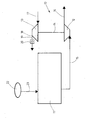
- the embodiment of the invention shown in the figure relates to the test a (single) exhaust gas turbocharger 10, which is associated with an internal combustion engine 11.
- internal combustion engine 11 may be both a gasoline engine so also to one Diesel engine act.
- an internal combustion engine 11 is used, the is installed together with the exhaust gas turbocharger 10. So it will be the turbocharger 10 tested on that internal combustion engine 11, with which the exhaust gas turbocharger 10 later also operated.
- the exhaust gas turbocharger 10 is in the so-called cold test with Ambient air pressure tested. It is the Internal combustion engine 11 is driven sluggishly, ie in the cold test of the exhaust gas turbocharger 10 also operated in the cold, unfired state.
- the exhaust gas turbocharger 10 has a turbine 12, which drives a compressor 13. To the compressor 13 is directly coupled to the turbine 12, preferably via a Turbine 12 with the compressor 13 connecting drive shaft 14th
- the internal combustion engine 11 is connected via a compressed air line 15 to the input side of Turbine 12 connected.
- the compressed air line 15 goes from the exhaust gas tract of the internal combustion engine 11 off.
- the compressed air line 15 to the exhaust manifold of the Internal combustion engine 11 connected.
- To drive the turbine 12 to Exhaust gas turbocharger 10 serving compressed air is the drive of the turbine 12th relaxes and passes over the outlet of the turbine 12 to the outside. This exit of the in the Turbine 12 relaxed air is symbolized by an arrow 16 in the drawing.
- the compressor 13 sucks in ambient air at its inlet side. This is by one Arrow 17 in the figure symbolizes.
- the of the turbine 12 via the drive shaft 14th driven compressor 13 compresses the intake air.
- the next to one Pressure side 18 the compressor 13 exiting compressed air is over one of the Pressure side 18 of the compressor 13 outgoing connecting line 19 to a throttle 20th directed.
- the throttle 20 is in the simplest case with a pinhole a hole diameter between 5 mm and 15 mm.
- the air is in the direction of Arrow 21 derived to the outside.
- the Connecting line 19 between the air outlet on the pressure side 18 of the compressor 13 and the throttle 20 is suitable for the application of transducers for Determining measured variables on the pressure side 18 of the compressor 13.
- the of the Compressed air driven turbine drives the compressor 13 via the drive shaft 14. This ensures unpressurized ambient air on the intake side and compresses it.
- the compressed and pressurized air flows through the Connecting line 19 to the throttle 20 and escapes behind the throttle 20 to the outside.
- the Throttle 20 keeps the pressure generated by the compressor 13 of the air in the connecting line 19 substantially upright, wherein in the connecting line 19 measurements of the compressed air can take place in the turbo map working compressor 13.
- an external compressed air source 22 is indicated.
- the external compressed air source 22 supplies pressurized air, which via a Connecting line 23 to the intake, preferably to the intake manifold, the Internal combustion engine 11 is passed.
- the precompressed air from the compressed air source 22 serves - if it is required or desired for the cold test - to charge the Internal combustion engine 11.
- the air mass which by the Combustion engine 11 and then flows through the turbine 12, increases. From this results in a further increase in the rotational speed of the exhaust gas turbocharger 10. It is however also conceivable to carry out the cold test of the exhaust gas turbocharger 10, without the Combustion engine 11 is supplied to the intake side of pre-compressed air. At this Procedure, the internal combustion engine sucks 11 unpressurised ambient air.
- the compressor air mass flow is determined by an air mass meter, which on the Suction side (arrow 17) of the compressor 13 is adapted.
- the boost pressure of the compressor 13 is determined on the pressure side 18 of the compressor 13 in front of the throttle 20.
- the Exhaust turbocharger speed is determined based on the speed of the turbine 12.
- each of the two cylinder banks is the Internal combustion engine associated with an exhaust gas turbocharger.
- Each exhaust gas turbocharger is from the Exhaust tract of a cylinder bank with a slowly driven internal combustion engine supplied compressed air supplied.
- the cold test proves that the two exhaust turbochargers tested with regard to their characteristics have too large deviations becomes at least one Exhaust gas turbocharger replaced with another exhaust gas turbocharger and hereby the Cold test repeated.
- the cold test is carried out so often until two turbochargers with the same or approximately the same characteristics as acceptable, that they are sufficient for later operation of the internal combustion engine Synchronize accuracy.
Landscapes
- Engineering & Computer Science (AREA)
- Chemical & Material Sciences (AREA)
- Combustion & Propulsion (AREA)
- Mechanical Engineering (AREA)
- General Engineering & Computer Science (AREA)
- Supercharger (AREA)
- Testing Of Engines (AREA)
- Engine Equipment That Uses Special Cycles (AREA)
Applications Claiming Priority (4)
| Application Number | Priority Date | Filing Date | Title |
|---|---|---|---|
| DE10256627 | 2002-12-03 | ||
| DE10256627 | 2002-12-03 | ||
| DE10300357A DE10300357A1 (de) | 2002-12-03 | 2003-01-09 | Verfahren zum Prüfen von Abgasturboladern |
| DE10300357 | 2003-01-09 |
Publications (2)
| Publication Number | Publication Date |
|---|---|
| EP1426578A1 true EP1426578A1 (fr) | 2004-06-09 |
| EP1426578B1 EP1426578B1 (fr) | 2006-04-12 |
Family
ID=32313573
Family Applications (1)
| Application Number | Title | Priority Date | Filing Date |
|---|---|---|---|
| EP03025937A Expired - Lifetime EP1426578B1 (fr) | 2002-12-03 | 2003-11-13 | Procédé pour tester les turbocompresseurs |
Country Status (3)
| Country | Link |
|---|---|
| EP (1) | EP1426578B1 (fr) |
| AT (1) | ATE323222T1 (fr) |
| DE (1) | DE50302950D1 (fr) |
Cited By (5)
| Publication number | Priority date | Publication date | Assignee | Title |
|---|---|---|---|---|
| DE102008031274B3 (de) * | 2008-07-02 | 2009-10-22 | Continental Automotive Gmbh | Verfahren und Vorrichtung zur Ermittlung von Kennfeldern eines Turboladers |
| EP2038633A4 (fr) * | 2006-06-30 | 2010-08-25 | Internat Engine Intellectual C | Procede et appareil de qualification des performances d'un turbocompresseur |
| WO2012113831A3 (fr) * | 2011-02-24 | 2012-10-26 | Avl List Gmbh | Procédé permettant l'essai de fonctionnement de turbomachines, et dispositif d'essai associé |
| DE102009041541C5 (de) * | 2009-09-15 | 2015-12-03 | Continental Automotive Gmbh | Verfahren und Vorrichtung zur Untersuchung des dynamischen Betriebsverhaltens eines Abgasturboladers |
| US20190353558A1 (en) * | 2018-05-21 | 2019-11-21 | Ford Motor Company | Device and method for cold testing engine component operation |
Citations (4)
| Publication number | Priority date | Publication date | Assignee | Title |
|---|---|---|---|---|
| EP0464822A1 (fr) * | 1990-07-05 | 1992-01-08 | IVECO FIAT S.p.A. | Procédé et dispositif de mesure de quantités physiques, en particulier la puissance, d'un moteur à combustion interne à aspiration d'air forcée turbocompressée |
| DE4223777C1 (de) * | 1992-07-18 | 1993-10-14 | Daimler Benz Ag | Verfahren zur motorunabhängigen, vergleichenden Überprüfung von baugleichen Abgasturboladern |
| JPH10196383A (ja) * | 1997-01-06 | 1998-07-28 | Koyo Seiko Co Ltd | ターボチャージャーの試験装置 |
| DE19837834A1 (de) * | 1998-08-20 | 2000-02-24 | Daimler Chrysler Ag | Verfahren zur Funktionsüberprüfung eines Abgasturboladers mit variabler Turbinengeometrie |
-
2003
- 2003-11-13 DE DE50302950T patent/DE50302950D1/de not_active Expired - Lifetime
- 2003-11-13 EP EP03025937A patent/EP1426578B1/fr not_active Expired - Lifetime
- 2003-11-13 AT AT03025937T patent/ATE323222T1/de active
Patent Citations (4)
| Publication number | Priority date | Publication date | Assignee | Title |
|---|---|---|---|---|
| EP0464822A1 (fr) * | 1990-07-05 | 1992-01-08 | IVECO FIAT S.p.A. | Procédé et dispositif de mesure de quantités physiques, en particulier la puissance, d'un moteur à combustion interne à aspiration d'air forcée turbocompressée |
| DE4223777C1 (de) * | 1992-07-18 | 1993-10-14 | Daimler Benz Ag | Verfahren zur motorunabhängigen, vergleichenden Überprüfung von baugleichen Abgasturboladern |
| JPH10196383A (ja) * | 1997-01-06 | 1998-07-28 | Koyo Seiko Co Ltd | ターボチャージャーの試験装置 |
| DE19837834A1 (de) * | 1998-08-20 | 2000-02-24 | Daimler Chrysler Ag | Verfahren zur Funktionsüberprüfung eines Abgasturboladers mit variabler Turbinengeometrie |
Non-Patent Citations (1)
| Title |
|---|
| PATENT ABSTRACTS OF JAPAN vol. 1998, no. 12 31 October 1998 (1998-10-31) * |
Cited By (6)
| Publication number | Priority date | Publication date | Assignee | Title |
|---|---|---|---|---|
| EP2038633A4 (fr) * | 2006-06-30 | 2010-08-25 | Internat Engine Intellectual C | Procede et appareil de qualification des performances d'un turbocompresseur |
| DE102008031274B3 (de) * | 2008-07-02 | 2009-10-22 | Continental Automotive Gmbh | Verfahren und Vorrichtung zur Ermittlung von Kennfeldern eines Turboladers |
| DE102009041541C5 (de) * | 2009-09-15 | 2015-12-03 | Continental Automotive Gmbh | Verfahren und Vorrichtung zur Untersuchung des dynamischen Betriebsverhaltens eines Abgasturboladers |
| WO2012113831A3 (fr) * | 2011-02-24 | 2012-10-26 | Avl List Gmbh | Procédé permettant l'essai de fonctionnement de turbomachines, et dispositif d'essai associé |
| US9632009B2 (en) | 2011-02-24 | 2017-04-25 | Avl List Gmbh | Method for functionally testing turbomachines, and test device therefor |
| US20190353558A1 (en) * | 2018-05-21 | 2019-11-21 | Ford Motor Company | Device and method for cold testing engine component operation |
Also Published As
| Publication number | Publication date |
|---|---|
| ATE323222T1 (de) | 2006-04-15 |
| DE50302950D1 (de) | 2006-05-24 |
| EP1426578B1 (fr) | 2006-04-12 |
Similar Documents
| Publication | Publication Date | Title |
|---|---|---|
| EP0856097B1 (fr) | Systeme pour detecter des ecarts de regime entre deux turbocompresseurs | |
| DE102007043440B3 (de) | Verfahren zum Ermitteln einer in einem Zylinder einer Brennkraftmaschine eingefangenen Luftmasse | |
| DE102011084977B4 (de) | Verfahren und Vorrichtung zum Prüfen von Verbrennungsmotoren | |
| EP2678654B1 (fr) | Procédé permettant l'essai de fonctionnement de turbomachines, et dispositif d'essai associé | |
| DE102017202554B4 (de) | Verfahren zum bestimmen eingeschlossener luft pro zylinder und gespülter luft pro zylinder in einem verbrennungsmotor | |
| EP1623103B1 (fr) | Procede pour controler le regime d'un bi-turbocompresseur | |
| DE19609923B4 (de) | Verfahren zur Überwachung einer Überhitzungsschutzmaßnahme im Volllastbetrieb einer Brennkraftmaschine | |
| EP1388654B1 (fr) | Moteur à combustion interne suralimenté | |
| DE10054843A1 (de) | Verfahren zur Begrenzung des Ladedrucks | |
| DE102006027422A1 (de) | Verfahren und Vorrichtung zum Überwachen eines Abgasturboladers | |
| EP1426578B1 (fr) | Procédé pour tester les turbocompresseurs | |
| DE102012209357A1 (de) | Verfahren und Vorrichtung zur Diagnose eines Schubumluftventils für eine Aufladeeinrichtung eines Verbrennungsmotors | |
| DE102024106128B3 (de) | Diagnoseverfahren für gekoppelte Abgasturbolader und Diagnosesystem | |
| DE102006022076A1 (de) | Transientes Partialflusssamplingsystem mit variabler Ansprechzeit und Verfahren dafür | |
| DE10300357A1 (de) | Verfahren zum Prüfen von Abgasturboladern | |
| CH620969A5 (en) | Internal combustion engine with two-stage turbocharging | |
| DE102009041541B3 (de) | Verfahren und Vorrichtung zur Untersuchung des dynamischen Betriebsverhaltens eines Abgasturboladers | |
| DE102012014144A1 (de) | Abgasaufladungs- und Abgasnachbehandlungsmodul für eine Brennkraftmaschine sowie Brennkraftmaschine | |
| DE102010029021A1 (de) | Verfahren und Vorrichtung zum Erkennen von Lecks im Einlasstrakt eines Verbrennungsmotors | |
| DE102018102070A1 (de) | System und verfahren zum ermitteln eines lader-antriebsverhältnisses in einem fahrzeugantriebssystem | |
| EP1588041B1 (fr) | Procede pour surveiller un moteur a combustion interne | |
| DE102009059931A1 (de) | Ermitteln und Parametrieren von Polynom-Modellen für Verbrennungsmotoren | |
| DE19841959A1 (de) | Verfahren und Vorrichtung zum Aufladen eines Verbrennungsmotors | |
| EP2126539B1 (fr) | Procédé et dispositif pour tester un turbomoteur | |
| DE19654137C2 (de) | Verfahren zum Prüfen eines end-/ oder teilmontierten Verbrennungsmotores |
Legal Events
| Date | Code | Title | Description |
|---|---|---|---|
| PUAI | Public reference made under article 153(3) epc to a published international application that has entered the european phase |
Free format text: ORIGINAL CODE: 0009012 |
|
| AK | Designated contracting states |
Kind code of ref document: A1 Designated state(s): AT BE BG CH CY CZ DE DK EE ES FI FR GB GR HU IE IT LI LU MC NL PT RO SE SI SK TR |
|
| AX | Request for extension of the european patent |
Extension state: AL LT LV MK |
|
| 17P | Request for examination filed |
Effective date: 20040629 |
|
| AKX | Designation fees paid |
Designated state(s): AT BE BG CH CY CZ DE DK EE ES FI FR GB GR HU IE IT LI LU MC NL PT RO SE SI SK TR |
|
| 17Q | First examination report despatched |
Effective date: 20050704 |
|
| GRAP | Despatch of communication of intention to grant a patent |
Free format text: ORIGINAL CODE: EPIDOSNIGR1 |
|
| GRAS | Grant fee paid |
Free format text: ORIGINAL CODE: EPIDOSNIGR3 |
|
| GRAA | (expected) grant |
Free format text: ORIGINAL CODE: 0009210 |
|
| AK | Designated contracting states |
Kind code of ref document: B1 Designated state(s): AT BE BG CH CY CZ DE DK EE ES FI FR GB GR HU IE IT LI LU MC NL PT RO SE SI SK TR |
|
| PG25 | Lapsed in a contracting state [announced via postgrant information from national office to epo] |
Ref country code: IE Free format text: LAPSE BECAUSE OF FAILURE TO SUBMIT A TRANSLATION OF THE DESCRIPTION OR TO PAY THE FEE WITHIN THE PRESCRIBED TIME-LIMIT Effective date: 20060412 Ref country code: IT Free format text: LAPSE BECAUSE OF FAILURE TO SUBMIT A TRANSLATION OF THE DESCRIPTION OR TO PAY THE FEE WITHIN THE PRESCRIBED TIME-LIMIT;WARNING: LAPSES OF ITALIAN PATENTS WITH EFFECTIVE DATE BEFORE 2007 MAY HAVE OCCURRED AT ANY TIME BEFORE 2007. THE CORRECT EFFECTIVE DATE MAY BE DIFFERENT FROM THE ONE RECORDED. Effective date: 20060412 Ref country code: FI Free format text: LAPSE BECAUSE OF FAILURE TO SUBMIT A TRANSLATION OF THE DESCRIPTION OR TO PAY THE FEE WITHIN THE PRESCRIBED TIME-LIMIT Effective date: 20060412 Ref country code: SI Free format text: LAPSE BECAUSE OF FAILURE TO SUBMIT A TRANSLATION OF THE DESCRIPTION OR TO PAY THE FEE WITHIN THE PRESCRIBED TIME-LIMIT Effective date: 20060412 Ref country code: RO Free format text: LAPSE BECAUSE OF FAILURE TO SUBMIT A TRANSLATION OF THE DESCRIPTION OR TO PAY THE FEE WITHIN THE PRESCRIBED TIME-LIMIT Effective date: 20060412 Ref country code: NL Free format text: LAPSE BECAUSE OF FAILURE TO SUBMIT A TRANSLATION OF THE DESCRIPTION OR TO PAY THE FEE WITHIN THE PRESCRIBED TIME-LIMIT Effective date: 20060412 |
|
| REG | Reference to a national code |
Ref country code: GB Ref legal event code: FG4D Free format text: NOT ENGLISH |
|
| REG | Reference to a national code |
Ref country code: CH Ref legal event code: EP |
|
| REF | Corresponds to: |
Ref document number: 50302950 Country of ref document: DE Date of ref document: 20060524 Kind code of ref document: P |
|
| REG | Reference to a national code |
Ref country code: CH Ref legal event code: NV Representative=s name: R. A. EGLI & CO. PATENTANWAELTE Ref country code: IE Ref legal event code: FG4D Free format text: LANGUAGE OF EP DOCUMENT: GERMAN |
|
| PG25 | Lapsed in a contracting state [announced via postgrant information from national office to epo] |
Ref country code: DK Free format text: LAPSE BECAUSE OF FAILURE TO SUBMIT A TRANSLATION OF THE DESCRIPTION OR TO PAY THE FEE WITHIN THE PRESCRIBED TIME-LIMIT Effective date: 20060712 |
|
| PG25 | Lapsed in a contracting state [announced via postgrant information from national office to epo] |
Ref country code: ES Free format text: LAPSE BECAUSE OF FAILURE TO SUBMIT A TRANSLATION OF THE DESCRIPTION OR TO PAY THE FEE WITHIN THE PRESCRIBED TIME-LIMIT Effective date: 20060723 |
|
| REG | Reference to a national code |
Ref country code: SE Ref legal event code: TRGR |
|
| GBT | Gb: translation of ep patent filed (gb section 77(6)(a)/1977) |
Effective date: 20060814 |
|
| PG25 | Lapsed in a contracting state [announced via postgrant information from national office to epo] |
Ref country code: PT Free format text: LAPSE BECAUSE OF FAILURE TO SUBMIT A TRANSLATION OF THE DESCRIPTION OR TO PAY THE FEE WITHIN THE PRESCRIBED TIME-LIMIT Effective date: 20060912 |
|
| REG | Reference to a national code |
Ref country code: HU Ref legal event code: AG4A Ref document number: E000571 Country of ref document: HU |
|
| NLV1 | Nl: lapsed or annulled due to failure to fulfill the requirements of art. 29p and 29m of the patents act | ||
| ET | Fr: translation filed | ||
| REG | Reference to a national code |
Ref country code: IE Ref legal event code: FD4D |
|
| PG25 | Lapsed in a contracting state [announced via postgrant information from national office to epo] |
Ref country code: MC Free format text: LAPSE BECAUSE OF NON-PAYMENT OF DUE FEES Effective date: 20061130 Ref country code: BE Free format text: LAPSE BECAUSE OF NON-PAYMENT OF DUE FEES Effective date: 20061130 |
|
| PLBE | No opposition filed within time limit |
Free format text: ORIGINAL CODE: 0009261 |
|
| STAA | Information on the status of an ep patent application or granted ep patent |
Free format text: STATUS: NO OPPOSITION FILED WITHIN TIME LIMIT |
|
| 26N | No opposition filed |
Effective date: 20070115 |
|
| BERE | Be: lapsed |
Owner name: JOHANN A. KRAUSE MASCHINENFABRIK G.M.B.H. Effective date: 20061130 |
|
| PG25 | Lapsed in a contracting state [announced via postgrant information from national office to epo] |
Ref country code: GR Free format text: LAPSE BECAUSE OF FAILURE TO SUBMIT A TRANSLATION OF THE DESCRIPTION OR TO PAY THE FEE WITHIN THE PRESCRIBED TIME-LIMIT Effective date: 20060713 |
|
| PG25 | Lapsed in a contracting state [announced via postgrant information from national office to epo] |
Ref country code: BG Free format text: LAPSE BECAUSE OF FAILURE TO SUBMIT A TRANSLATION OF THE DESCRIPTION OR TO PAY THE FEE WITHIN THE PRESCRIBED TIME-LIMIT Effective date: 20060712 Ref country code: EE Free format text: LAPSE BECAUSE OF FAILURE TO SUBMIT A TRANSLATION OF THE DESCRIPTION OR TO PAY THE FEE WITHIN THE PRESCRIBED TIME-LIMIT Effective date: 20060412 |
|
| PG25 | Lapsed in a contracting state [announced via postgrant information from national office to epo] |
Ref country code: LU Free format text: LAPSE BECAUSE OF NON-PAYMENT OF DUE FEES Effective date: 20061113 |
|
| PG25 | Lapsed in a contracting state [announced via postgrant information from national office to epo] |
Ref country code: CY Free format text: LAPSE BECAUSE OF FAILURE TO SUBMIT A TRANSLATION OF THE DESCRIPTION OR TO PAY THE FEE WITHIN THE PRESCRIBED TIME-LIMIT Effective date: 20060412 |
|
| PGFP | Annual fee paid to national office [announced via postgrant information from national office to epo] |
Ref country code: SK Payment date: 20131112 Year of fee payment: 11 Ref country code: AT Payment date: 20131113 Year of fee payment: 11 Ref country code: CH Payment date: 20131121 Year of fee payment: 11 |
|
| PGFP | Annual fee paid to national office [announced via postgrant information from national office to epo] |
Ref country code: TR Payment date: 20131030 Year of fee payment: 11 |
|
| REG | Reference to a national code |
Ref country code: CH Ref legal event code: PL |
|
| REG | Reference to a national code |
Ref country code: AT Ref legal event code: MM01 Ref document number: 323222 Country of ref document: AT Kind code of ref document: T Effective date: 20141113 |
|
| PG25 | Lapsed in a contracting state [announced via postgrant information from national office to epo] |
Ref country code: CH Free format text: LAPSE BECAUSE OF NON-PAYMENT OF DUE FEES Effective date: 20141130 Ref country code: LI Free format text: LAPSE BECAUSE OF NON-PAYMENT OF DUE FEES Effective date: 20141130 Ref country code: SK Free format text: LAPSE BECAUSE OF NON-PAYMENT OF DUE FEES Effective date: 20141113 |
|
| REG | Reference to a national code |
Ref country code: SK Ref legal event code: MM4A Ref document number: E 782 Country of ref document: SK Effective date: 20141113 |
|
| PG25 | Lapsed in a contracting state [announced via postgrant information from national office to epo] |
Ref country code: AT Free format text: LAPSE BECAUSE OF NON-PAYMENT OF DUE FEES Effective date: 20141113 |
|
| REG | Reference to a national code |
Ref country code: FR Ref legal event code: PLFP Year of fee payment: 13 |
|
| PGFP | Annual fee paid to national office [announced via postgrant information from national office to epo] |
Ref country code: IT Payment date: 20151125 Year of fee payment: 13 Ref country code: GB Payment date: 20151118 Year of fee payment: 13 |
|
| PGFP | Annual fee paid to national office [announced via postgrant information from national office to epo] |
Ref country code: SE Payment date: 20151118 Year of fee payment: 13 Ref country code: HU Payment date: 20151118 Year of fee payment: 13 Ref country code: CZ Payment date: 20151111 Year of fee payment: 13 Ref country code: FR Payment date: 20151119 Year of fee payment: 13 |
|
| REG | Reference to a national code |
Ref country code: SE Ref legal event code: EUG |
|
| GBPC | Gb: european patent ceased through non-payment of renewal fee |
Effective date: 20161113 |
|
| PG25 | Lapsed in a contracting state [announced via postgrant information from national office to epo] |
Ref country code: CZ Free format text: LAPSE BECAUSE OF NON-PAYMENT OF DUE FEES Effective date: 20161113 |
|
| REG | Reference to a national code |
Ref country code: FR Ref legal event code: ST Effective date: 20170731 |
|
| PG25 | Lapsed in a contracting state [announced via postgrant information from national office to epo] |
Ref country code: HU Free format text: LAPSE BECAUSE OF NON-PAYMENT OF DUE FEES Effective date: 20161114 Ref country code: TR Free format text: LAPSE BECAUSE OF NON-PAYMENT OF DUE FEES Effective date: 20141113 Ref country code: SE Free format text: LAPSE BECAUSE OF NON-PAYMENT OF DUE FEES Effective date: 20161114 |
|
| PG25 | Lapsed in a contracting state [announced via postgrant information from national office to epo] |
Ref country code: FR Free format text: LAPSE BECAUSE OF NON-PAYMENT OF DUE FEES Effective date: 20161130 Ref country code: IT Free format text: LAPSE BECAUSE OF NON-PAYMENT OF DUE FEES Effective date: 20161113 |
|
| PG25 | Lapsed in a contracting state [announced via postgrant information from national office to epo] |
Ref country code: GB Free format text: LAPSE BECAUSE OF NON-PAYMENT OF DUE FEES Effective date: 20161113 |
|
| PGFP | Annual fee paid to national office [announced via postgrant information from national office to epo] |
Ref country code: DE Payment date: 20171121 Year of fee payment: 15 |
|
| REG | Reference to a national code |
Ref country code: DE Ref legal event code: R119 Ref document number: 50302950 Country of ref document: DE |
|
| PG25 | Lapsed in a contracting state [announced via postgrant information from national office to epo] |
Ref country code: DE Free format text: LAPSE BECAUSE OF NON-PAYMENT OF DUE FEES Effective date: 20190601 |