EP1426610A1 - Dispositif d'amortissement des ondes de pression pour système d'injection de carburant - Google Patents
Dispositif d'amortissement des ondes de pression pour système d'injection de carburant Download PDFInfo
- Publication number
- EP1426610A1 EP1426610A1 EP03293029A EP03293029A EP1426610A1 EP 1426610 A1 EP1426610 A1 EP 1426610A1 EP 03293029 A EP03293029 A EP 03293029A EP 03293029 A EP03293029 A EP 03293029A EP 1426610 A1 EP1426610 A1 EP 1426610A1
- Authority
- EP
- European Patent Office
- Prior art keywords
- fuel
- pressure
- damping device
- piston
- main body
- Prior art date
- Legal status (The legal status is an assumption and is not a legal conclusion. Google has not performed a legal analysis and makes no representation as to the accuracy of the status listed.)
- Granted
Links
Images




Classifications
-
- F—MECHANICAL ENGINEERING; LIGHTING; HEATING; WEAPONS; BLASTING
- F02—COMBUSTION ENGINES; HOT-GAS OR COMBUSTION-PRODUCT ENGINE PLANTS
- F02M—SUPPLYING COMBUSTION ENGINES IN GENERAL WITH COMBUSTIBLE MIXTURES OR CONSTITUENTS THEREOF
- F02M55/00—Fuel-injection apparatus characterised by their fuel conduits or their venting means; Arrangements of conduits between fuel tank and pump F02M37/00
- F02M55/04—Means for damping vibrations or pressure fluctuations in injection pump inlets or outlets
-
- F—MECHANICAL ENGINEERING; LIGHTING; HEATING; WEAPONS; BLASTING
- F02—COMBUSTION ENGINES; HOT-GAS OR COMBUSTION-PRODUCT ENGINE PLANTS
- F02M—SUPPLYING COMBUSTION ENGINES IN GENERAL WITH COMBUSTIBLE MIXTURES OR CONSTITUENTS THEREOF
- F02M55/00—Fuel-injection apparatus characterised by their fuel conduits or their venting means; Arrangements of conduits between fuel tank and pump F02M37/00
- F02M55/02—Conduits between injection pumps and injectors, e.g. conduits between pump and common-rail or conduits between common-rail and injectors
- F02M55/025—Common rails
-
- F—MECHANICAL ENGINEERING; LIGHTING; HEATING; WEAPONS; BLASTING
- F02—COMBUSTION ENGINES; HOT-GAS OR COMBUSTION-PRODUCT ENGINE PLANTS
- F02M—SUPPLYING COMBUSTION ENGINES IN GENERAL WITH COMBUSTIBLE MIXTURES OR CONSTITUENTS THEREOF
- F02M63/00—Other fuel-injection apparatus having pertinent characteristics not provided for in groups F02M39/00 - F02M57/00 or F02M67/00; Details, component parts, or accessories of fuel-injection apparatus, not provided for in, or of interest apart from, the apparatus of groups F02M39/00 - F02M61/00 or F02M67/00; Combination of fuel pump with other devices, e.g. lubricating oil pump
- F02M63/02—Fuel-injection apparatus having several injectors fed by a common pumping element, or having several pumping elements feeding a common injector; Fuel-injection apparatus having provisions for cutting-out pumps, pumping elements, or injectors; Fuel-injection apparatus having provisions for variably interconnecting pumping elements and injectors alternatively
- F02M63/0225—Fuel-injection apparatus having a common rail feeding several injectors ; Means for varying pressure in common rails; Pumps feeding common rails
-
- F—MECHANICAL ENGINEERING; LIGHTING; HEATING; WEAPONS; BLASTING
- F02—COMBUSTION ENGINES; HOT-GAS OR COMBUSTION-PRODUCT ENGINE PLANTS
- F02M—SUPPLYING COMBUSTION ENGINES IN GENERAL WITH COMBUSTIBLE MIXTURES OR CONSTITUENTS THEREOF
- F02M2200/00—Details of fuel-injection apparatus, not otherwise provided for
- F02M2200/28—Details of throttles in fuel-injection apparatus
-
- F—MECHANICAL ENGINEERING; LIGHTING; HEATING; WEAPONS; BLASTING
- F02—COMBUSTION ENGINES; HOT-GAS OR COMBUSTION-PRODUCT ENGINE PLANTS
- F02M—SUPPLYING COMBUSTION ENGINES IN GENERAL WITH COMBUSTIBLE MIXTURES OR CONSTITUENTS THEREOF
- F02M2200/00—Details of fuel-injection apparatus, not otherwise provided for
- F02M2200/31—Fuel-injection apparatus having hydraulic pressure fluctuations damping elements
- F02M2200/315—Fuel-injection apparatus having hydraulic pressure fluctuations damping elements for damping fuel pressure fluctuations
Definitions
- the present invention relates to a pressurized fuel injection system for a internal combustion engine.
- the invention relates to a fuel injection system comprising a common fuel distribution rail (from English "common rail"), this distribution ramp being on the one hand connected to a high pressure pump, and on the other hand to a plurality of fuel injectors, each of them cooperating with a chamber of associated combustion.
- a common fuel distribution rail from English "common rail"
- this distribution ramp being on the one hand connected to a high pressure pump, and on the other hand to a plurality of fuel injectors, each of them cooperating with a chamber of associated combustion.
- the present invention also relates to a device for damping pressure waves intended to equip such a system injection.
- a solution known in the state of the technique involves inserting one or more damping devices of the pressure waves on the injection ducts connected to the injectors of the system, in order to create pressure losses intended to reduce pressure fluctuations resulting from injections previously performed.
- the present invention aims to propose a device for damping the waves of pressure with satisfactory efficiency in terms of weakening of interactions occurring between successive injections, while not generating than small engine performance losses.
- the subject of the invention is a damping device for pressure waves intended to equip a fuel injection system for internal combustion engine, common rail fuel distribution, the device comprising means of restriction capable of causing losses of charge in the injection system when they are crossed by the flowing fuel.
- the restriction means are made of such that the pressure losses caused by the flow of fuel through these means of restriction towards the high pressure pump are greater than the pressure losses caused by the flow of fuel through these same means of restriction towards at least one of the injectors injection system.
- the design of the device according to the invention makes it possible to generate losses different load in the direction of flow of the fuel in the injection system, these losses of load being lower during the injection phases of fuel intended to expel the latter in the direction of a system injector.
- the invention furthermore relates to a pressurized fuel injection system for internal combustion engine, to a common rail of fuel distribution, comprising a plurality injectors.
- the system comprises in in addition to at least one wave damping device pressure such as that also object of the present invention and described above.
- the subject of the invention is a damping device pressure waves intended to equip a system fuel injection system for a combustion engine internal, common rail fuel distribution, the device comprising restriction means capable of generating losses in the system injection when they are crossed by the fuel in flow.
- the device furthermore includes a bypass also to be crossed by the fuel, exclusively when the fuel pressure flowing through the device exceeds a predetermined value.
- the damping device according to the invention makes it possible to obtain an efficiency satisfactory in terms of weakening interactions occurring between injections successive stages, for example by providing means of classic restrictions that may fill a such function, and whose behavior is particularly satisfactory for low flow rates and low fuel pressures.
- the addition parallel of a bypass activated only when the fuel pressure exceeds a predetermined value considerably reduces the losses of engine performance, especially for the strong flow rates and high fuel pressures.
- the subject of the invention is a damping device pressure waves intended to equip a system fuel injection system for a combustion engine internal, common rail fuel distribution, the device comprising restriction means defining a restriction zone capable of generating pressure losses in the injection system when it is crossed by the fuel in flow.
- the restriction zone has a variable geometry depending on the fuel pressure flowing through the device.
- variable geometry restriction area allows for provide a different level of pressure drop in depending on the fuel pressure.
- the device 114 can take place substantially at the same locations as those occupied by the damping devices of the prior art, to know about the injection pipes, close to the common distribution ramp and its orifices exit.
- the damping device 114 can also be arranged and adapted to equip directly one of the outlets of the ramp common distribution, the inlet of this same common rail, the feed duct, or again the outlet of the high pressure pump.
- the device can be arranged in downstream and / or upstream of the common system ramp injection.
- the damping device 114 is interposed between two sections 16a and 16b of a conduit injection, the device 114 being for example assembled by welding to these various sections 16a and 16b of similar inner section.
- the damping device 114 pressure waves comprises means of restriction in the form of at least one nozzle asymmetrical 116, and preferably only one.
- This nozzle asymmetrical 116 has a first profile 118 and a second profile 120, the latter being separated by a junction area 122 of small section.
- the first and second profiles 118 and 120 are arranged so as to be respectively in contact with the upper sections and lower 16a and 16b.
- the first profile 118 is substantially conical shape, while the second profile 120 is of substantially straight shape.
- the straight form of the conventional bore type the second profile 120 has an inner section substantially identical to the inner section of the lower section 16b, and well above the section of the junction zone 122.
- the conical shape of the first profile 118 is made of so that the widest portion of the cone lies in contact with the upper section 16a, and so that the narrowest portion of the cone is in contact of the junction zone 122.
- the widest portion of the cone has a section substantially identical to the inner section of the upper section 16a, and the narrowest portion of the cone has a section substantially identical to the section of the junction zone 122, this one taking for example the shape of a simple bore.
- the asymmetrical nozzle 116 proposed, easily achievable in one piece by machining, provides satisfactory efficiency in terms of weakening of interactions occurring between successive fuel injections, in the sense that the pressure drops observed during the flow of the fuel in the direction represented by arrow A can be relatively important.
- the nozzle 116 generates only very small losses in performance of the engine, to the extent that the losses of load observed during the flow of fuel in the direction represented by the arrow B can be low enough to significantly limit loss of injection flow at high pressure.
- first and second profile 118,120 and of the junction zone 122 of the asymmetrical nozzle 116 can be adapted according to the various losses desired charge.
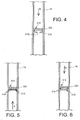
- damping device 214 waves of pressure, according to a second embodiment preferred embodiment of the present invention.
- the damping device 214 of the pressure waves has restriction means including a deformable element 216 of the membrane type of material flexible, this membrane 216 being provided with an opening 218 single and preferentially of circular section.
- Membrane 216 also has a section of substantially circular shape, and is assembled fixed inside the injection pipe 16 of so that its periphery totally marries the inside of this duct 16, the inner section of which is therefore substantially identical to the section circular of this membrane 216. It should be noted that the assembly of the membrane 216 is for example by gluing or using inserts (no represented) so that its periphery is always fixed compared to the injection duct 16.
- the flowing fuel in the injection pipe 16 and arriving at the level of the membrane 216 can only the to cross through a passage defined by the opening 218, preferably in the center.
- the means of restriction further comprise a support element 220 which does not create no or little loss of load, preferably of the type rigid element in the shape of a cross.
- a support element 220 which does not create no or little loss of load, preferably of the type rigid element in the shape of a cross.
- the action exerted by the fuel in flow on the flexible membrane 216 causes only a plating of it against the element 220 support downstream.
- the membrane 216 as well as its central opening 218 are then almost not deformed in relation to their rest configuration in which they are not subject to any mechanical stress, especially because of the contact existing original between the support element 220 forming stop and the flexible membrane 216.
- the flowing fuel first crosses the rigid support element 220, before coming to exert an action on the membrane flexible 216 means of restriction.
- a positioning upstream of the element 220 does not allow him to fulfill his role of stop for the flexible membrane 216, so this membrane 216 as well as its central opening 218 are largely distorted by the action of fuel in flow in the injection conduit 16.
- the section of the opening 218 is advantageously variable depending on the level of deformation of the flexible membrane 216 comparable to a deformable diaphragm, this level of deformation being directly dependent on the flow characteristics fuel in the injection system, and therefore closely related to the operating point of the motor.
- the opening 218 has a section greater than that observed in the case of a fuel flow in the direction represented by the arrow A.
- the deformable element takes the form of a grid deformable 316, having a plurality of openings 318 whose section is likely to grow more to the deformation of the gate 316, caused by the action of the flowing fuel in the direction represented by the arrow B in FIG.
- the damping device 114 is interposed between two sections 16a and 16b of an injection pipe, the 114 device being for example assembled by welding to these various sections 16a and 16b of inner section similar.
- the damping device 114 'waves pressure comprises formed restriction means by an outer body 116 'and a main body 118'.
- the outer body 116 ' is indifferently shaped cylindrical with circular or parallelepiped section, and is provided with a fuel inlet 120 'in contact with the upper section 16a, as well as an outlet 122 'fuel in contact with the lower section 16b.
- the main body 118 ' is housed in inside the outer body 116 ', preferably centric way.
- the means of restriction therefore form a zone of restriction 124 'of substantially annular shape, this zone 124 'being located between the outer body 116' and the main body 118 '.
- the restriction zone 124 is a zone annular operating in thin-layer flow (viscous flow, governed for example by equations of Naviers-Stockes).
- this type of zone of restriction in which the distance between the walls opposite is far inferior and the length of the flow, allows to obtain losses of charges varying linearly with flow fuel injection.
- the means of restriction used in this first mode of preferred embodiment of the present invention provide a very good efficiency, especially for beaches of relatively low pressure and flow.
- the distance between opposite walls of the flow zone 124 ' i.e. the distance between an inner wall 126 'of the body 116 'outside and an outer wall 128 of the body principal 118 ', may be of the order of 20 to 50 be of the order of 20 to 50 e between the opposite walls of the flow zone 124 ', i.e. the distance between an inner wall 126 of the outer body 116 'and an outer wall 128 of the main body 118 ', can be of the order of 20 to 50 microns.
- the length of the flow of the restriction zone 124 ' is at tell the value of the average circumference of the area annular 124 'can be a few millimeters.
- the damping device 114 ' further comprises a bypass 130 made in the body principal 118 '.
- the bypass 130 is likely to be crossed by the fuel, so to allow a flow of fuel, and this only when the fuel pressure in flow through the device 114 'exceeds a predetermined value.
- the main body 118 'of the device Damping 114 ' has an inner chamber 132, in which a piston 134 is slidable.
- the main body 118 is provided with an opening 136 arranged opposite the entrance of fuel 120 ', and opening on the one hand in the restriction zone 124 'and secondly in the inner chamber 132.
- the bypass 130 also preferably taking the form of a simple bore arranged next to the exit of 122 'fuel, is practiced in the main body 118 'so as to lead on the one hand into the zone of restriction 124 'and secondly in the room Inside 132.
- the piston 134 slidably mounted in the inner chamber 132 has a first end 134a and a second end 134b.
- the first end 134a is in contact with the fuel located in the inner chamber 132 and introduced into it since opening 136, practiced in the main body 118 of the device 114 '.
- the second end 134b of the piston 134 is in contact with resilient means, preferably constituted by a spring 138 extending to inside the inner chamber 132, and also placed against a closure cap 139 of the outer body 116 '.
- the cap 139 is provided with a orifice 140 opening on the one hand in the chamber 132 and on the other hand outside the damping device 114 ', this orifice 140 being connected to a leakage tank (not shown).
- the piston is constantly subjected to two opposite actions, exerted respectively by the fuel on the first end 134a and by the spring 138 on the second end 134b.
- the action exerted by the fuel on the first end 134a of the piston 134 then drives a moving the latter into the inner chamber 132 of the main body 118 ', so that it releases at least partially bypass 130.
- the fuel borrows not only the restricted area 124, but also a parallel flow path, constituted in particular by the by-pass 130.
- the predetermined pressure value of fuel can be set to a value from which it is considered that the losses of charges generated by the restriction means, when fuel injection phases, would become too much critics to hope for optimal functioning of the engine, both injection pressure losses effective are high.
- the spring 138 must be dimensioned accordingly to allow proper sliding of the piston 134 in the inner chamber 132.
- the means of restriction of the device 114 are short-circuited, as far as 85% to 90% of the fuel take by-pass 130 to reach the injectors of the system, this bypass 130 only causing relatively small losses of expenses. So, when fuel injection at high pressures, the low proportion of fuel passing through the means of restriction alone does not allow to provoke a damping effect in the system, and does not generate so that very low injection pressure losses effective, and that a slight decrease in maximum quantities injected at the point of power.
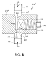
- damping device 214 'of pressure waves comprises a main body 218 ', substantially similar to the main body 118 'of the device 114' according to the first preferred embodiment.
- the body principal 218 is indifferently cylindrical to circular or parallelepipedal section, and is provided a fuel inlet 220 'in contact with the upper section 16a, as well as an output of fuel 222 in contact with the lower section 16b.
- the main body 218 'of the damping device 214' has an interior room 232, in which a piston 234 is slidable.
- the main body 218 is also provided with an opening 236 opening directly on the one hand in the fuel inlet 220 and secondly in the inner chamber 232.
- the means of restriction take the form of at least a nozzle 224, preferably one, practiced in the main body 218 ', so that it opens directly on the one hand in the inner chamber 232 and secondly in the fuel outlet 222.
- the damping device 214 further comprises a bypass 230 practiced in the body principal 218 ', this bypass 230 being similar to the bypass 130 of the damping device 114 'according to the first embodiment referred.
- the bypass 230 is likely to be crossed by the fuel, in order to allow a flow of fuel, and this only when the fuel pressure in flow through the device 214 'exceeds a predetermined value.
- the bypass 230 also preferably taking the form of a simple bore, is practiced in the body principal 218 'so as to lead directly to a part in the fuel outlet 222 and secondly in the inner chamber 232.
- the piston 234 slidably mounted in the inner chamber 132 has a first end 234a and a second end 234b.
- the first end 234a is in contact with the fuel located in the inner chamber 232 and introduced into it since opening 236, practiced in the main body 218 'of the device 214 '.
- the second end 234b of the piston 234 is in contact with resilient means, preferably constituted by a spring 238 extending to inside the inner chamber 232, and also placed in abutment against a closure cap 239 of the main body 218 '.
- the cap 239 is provided with a orifice 240 opening on the one hand in the chamber inside 232 and on the other hand outside the damping device 214 ', this orifice 240 being connected to a leakage tank (not shown).
- By-pass 230 being closed during low-pressure injections, transiting fuel between the fuel inlet and outlet 220 and 222 exclusively borrows the jet 224 through which it undergoes significant losses of load providing a good damping efficiency of waves pressure, this jet 224 being also totally released by the piston 234, whatever the pressure fuel inside the device 214 '.
- FIGS. 9 and 10 it is represented a device for damping 114 waves pressure, according to another preferred embodiment of the present invention.
- the damping device 114 is interposed between two sections 16a and 16b of a conduit injection, the device 114 "being for example assembled by welding to these various sections 16a and 16b of similar inner section.
- the damping device 114 "pressure waves comprises a main body 118 "indifferently cylindrical in section circular or parallelepipedic, and is equipped with a 120 "fuel inlet in contact with the section upper 16a, as well as a fuel outlet 122 " in contact with the lower section 16b.
- the main body 118 "of the damping device 114" has an inner wall 131 defining a chamber 132 ", in which a piston 134 is adapted to slide.
- the main body 118 " is also provided with a first zone of passage taking preferentially the shape of a single opening 136 ", the latter opening directly on the one hand in the fuel inlet 120 “and secondly in the 132 "inner chamber, the 136" opening, taking example the shape of a simple bore, authorized by therefore a fuel flow between the chamber 132 "of the main body 118" and the entrance of 120 "fuel.
- the main body 118 " is equipped with a second passage zone also taking preferentially the shape of a single opening 124 ", the latter opening directly on the one hand in the fuel outlet 122 “and secondly in the inner chamber 132 ".
- the opening 124 taking for example the shape of a simple bore, authorized by therefore a fuel flow between the chamber 132 "of the main body 118" and the exit of 122 "fuel.
- the restriction means comprise the body main 118 "and the piston 134". Indeed, a zone of restriction 137, defined by these restriction means and through which is able to flow the fuel, is arranged between a first end 134a of the piston 134 "and a lateral surface 131a of the inner wall 131 defining the inner chamber 132.
- the first end 134 "of the piston 134" and the lateral surface 131a of the inner wall 131 are located parallel to one another. In addition, they are each substantially flat, and preferably of square or circular shape.
- zone of restriction 137 allows to consider that this area operates in thin-film flow (flow viscous, governed for example by the equations of Naviers-Stokes).
- the piston 134 is provided with a second end 134b, the latter being in contact with elastic means preferentially taking the shape of a deformable pellet 142.
- the deformable pellet 142 is placed in the interior chamber 132 "so as to be on the one hand contact with the second end 134b "of the piston 134", and secondly abuts against a locking screw 144, also mounted in the 132 "inner chamber.
- the locking screw 144 presents a through orifice 146, and is placed opposite and at distance from a closure cap 139 "of the body 118.
- the plug 139 is provided with an orifice 140 "opening on the one hand in the inner chamber 132 and on the other hand outside the device of damping 114 ", this orifice 140" being connected to a leakage tank (not shown).
- the deformable pellet 142 is then likely to have an action in the opposite direction to that exerted on the piston 134 "by the fuel located in the restriction zone 137. In this way, depending the difference in intensity between the various actions to which the piston 134 "is constantly subjected, this one is able to move in the 132 "inner chamber, and therefore likely to vary the geometry of the Restriction zone 137.
- the first end 134a "and the lateral surface 131a present substantially complementary forms conical. It is specified that the axis of these elements of conical shape is confused with a main axis 148 of the damping device 114 ", this axis 148 also representing the sliding direction of the piston 134 "inside the chamber 132" of the body principal 118 ".
- the opening 124 "constituting the second passage zone and the fuel outlet 122 " are arranged so as to be opposite the first end 134a of the piston
- these elements each have an axis coincides with the main axis 148 of the device 114 ", and perpendicular to a common axis (not shown) at the opening 136 "constituting the first zone of passage and at the fuel inlet 120 ".
- the second end 134b "of the piston 134" is coupled to a piezoelectric actuator 150, placed in the chamber interior 132 "of the main body 118" and adapted to receive at least one piece of information about the fuel pressure in a high pressure part of the high pressure injection system.
- the piezoelectric actuator 150 is then susceptible to control the sliding of the piston 134 "in the interior chamber 132 "of the main body 118", so that the piston slides away from the surface 131a of the inner wall 131 when the fuel pressure in the restriction zone 137 increases, and vice versa.
- damping device 214 waves of pressure, according to a preferred embodiment of the present invention.
- the damping device 214 is interposed between two sections 16a and 16b of a conduit injection device, the device 214 "being for example assembled by welding to these various sections 16a and 16b of similar inner section.
- the damping device 214 " pressure waves comprises a main body 218 ", substantially similar to the main body 118 "of the 114 “device according to the first embodiment prefer.
- the main body 218 " is indifferently cylindrical shape with circular section or parallelepiped, and is equipped with an entrance 220 "fuel in contact with the upper section 16a, as well as a fuel outlet 222 "in contact with the lower section 16b.
- the main body 218 "of the damping device 214" has an inner wall 231 defining a chamber 232 ", in which a piston 234" is fit to slide.
- the main body 218 is also provided with a first zone of passage taking preferentially the shape of a single opening 236 opening directly on the one hand in the entrance of fuel 220 "and secondly in the room inner 232 ", opening 236", taking for example the shape of a simple bore, therefore allows a fuel flow between the inner chamber 232 "main body 218" and fuel inlet 220 ".
- main body 218 is also provided with a second passage area opening directly on the one hand in the 220 "fuel inlet and secondly in the inner chamber 232 ", this second zone of passage thus authorizing a fuel flow between the inner chamber 232 "main body 218" and fuel inlet 220 ".
- the second zone of passage takes the form of a plurality of nozzles 224 ", which can be closed or released by the piston 234 ".
- the device 214 " is designed in such a way that at least a fraction of a nozzle 224 "of the second zone of passage is always released by the piston 234 ", regardless of the fuel pressure prevailing at inside the damping device 214 ".
- the means for restriction comprising the main body 218 " define a 237 restriction zone across which is suitable for flowing fuel, this zone 237 being constituted by the portion of the second zone passage unobstructed by the piston 234 ", namely by the nozzle (s) 224 “or jet fractions not covered by the same piston 234 ".
- the piston 234 "slidably mounted in the 232 "inner chamber has a first end 234a "and a second end 234b".
- the first end 234a is in contact with the fuel located in the inner chamber 232 "and introduced into it from the opening 236 ", practiced in the main body 218 "of the device 214.
- the second end 234b “of the piston 234 is in contact with resilient means, preferably constituted by a spring 238 extending to inside the inner chamber 232 ", and also placed in abutment against a closure cap 239 of the main body 218 ".
- the cap 239 is provided with a orifice 240 "opening on the one hand in the chamber 232 "and on the other hand outside the damping device 214 ", this orifice 240" being connected to a leakage tank (not shown).
- the second passage area consists of a single opening, whose portion not closed by the piston 234 "forms the restriction zone 237 through which is apt to run off the fuel.
- the unique opening practiced in the body principal 218 " may be adapted to obtain a specific evolution of pressure losses according to of the fuel pressure prevailing inside the device 214 ".
- the opening can be section substantially rectangular or triangular.
- the single opening may also have a rectangular section of which one end is substantially parabolic.
- the damping device 314 "pressure waves comprises a main body 318 "indifferently cylindrical section circular or parallelepipedic, and is equipped with a 320 "fuel inlet in contact with the section upper 16a, as well as a fuel outlet 322 in contact with the lower section 16b.
- the main body 318 "of the device cushion 314 " has an inner wall 331 defining an inner chamber 332. Furthermore, the main body 318 "is also provided with a first zone of passage preferentially taking the form of a single opening 336, the latter opening directly on the one hand in the entrance of fuel 320 "and secondly in the room
- the opening 336 taking for example the shape of a simple bore, therefore allows a fuel flow between the inner chamber 332 of the main body 318 "and the fuel inlet 320".
- the main body 318 is equipped with a second passage zone also taking preferentially the shape of a single opening 324, the latter opening directly on the one hand in the fuel outlet 322 and secondly in the interior room 332.
- the opening 324 taking by example the shape of a simple bore, authorized by therefore a fuel flow between the chamber interior 332 of the main body 318 and the exit of fuel 322.
- the restriction means comprise two capsules 350 arranged spaced apart in the inner chamber 332, each of these two capsules 350 being filled with a compressible fluid 351 and closed by means of a flexible membrane 352.
- the membranes hoses 352 substantially parallel and located in look at each other are arranged parallel to a common axis (not shown) of the openings 336 and 324, and perpendicular to a main axis 348 of the damping device 314 ".
- the flexible membranes 352 defining the zone of restriction 337 are then constantly subject to two opposite meaning, exercised respectively by the compressible fluid 351 and the fuel flowing at within the Restricted Area 337. From this way, depending on the difference in intensity between the various actions generated, the membranes flexible 352 are able to deform and therefore likely to vary the geometry of the area of restriction 337.
- the invention relates to a system fuel injection system for a combustion engine internally, as described in the state part of the prior art, the system being equipped with one or several devices for damping the waves of pressure, each of these damping devices taking the form of any of the modes of preferred embodiments presented above.
Landscapes
- Engineering & Computer Science (AREA)
- Chemical & Material Sciences (AREA)
- Combustion & Propulsion (AREA)
- Mechanical Engineering (AREA)
- General Engineering & Computer Science (AREA)
- Fuel-Injection Apparatus (AREA)
Abstract
Description
- la figure 1 représente une vue en coupe longitudinale d'un dispositif d'amortissement des ondes, selon un premier mode de réalisation préféré de la présente invention,
- la figure 2 représente une vue en coupe longitudinale d'un dispositif d'amortissement des ondes, selon un second mode de réalisation préféré de la présente invention,
- la figure 3 représente une vue en coupe prise le long de la ligne III-III de la figure 2,
- la figure 4 représente une vue en coupe similaire à celle représentée sur la figure 2, lorsque le carburant s'écoule en direction d'un injecteur du système d'injection,
- la figure 5 représente une vue en coupe longitudinale d'un dispositif d'amortissement des ondes, selon un troisième mode de réalisation préféré de la présente invention, et
- la figure 6 représente une vue en coupe similaire à celle représentée sur la figure 5, lorsque le carburant s'écoule en direction d'un injecteur du système d'injection.
- la figure 7 représente une vue en coupe longitudinale d'un dispositif d'amortissement des ondes, selon un premier mode de réalisation préféré de la présente invention, et
- la figure 8 représente une vue en coupe longitudinale d'un dispositif d'amortissement des ondes, selon un second mode de réalisation préféré de la présente invention.
- la figure 9 représente une vue en coupe longitudinale d'un dispositif d'amortissement des ondes de pression destiné à équiper un système d'injection à rampe commune de distribution, selon un premier mode de réalisation préféré de la présente invention,
- la figure 10 représente une vue en coupe prise le long de la ligne II-II de la figure 9,
- la figure 11 représente une vue en coupe longitudinale d'un dispositif d'amortissement des ondes de pression similaire à celui représenté sur la figure 1, selon une solution alternative,
- la figure 12 représente une vue en coupe longitudinale d'un dispositif d'amortissement des ondes de pression similaire à celui représenté sur la figure 1, selon une autre solution alternative,
- la figure 13 représente une vue en coupe longitudinale d'un dispositif d'amortissement des ondes de pression destiné à équiper un système d'injection à rampe commune de distribution, selon un second mode de réalisation préféré de la présente invention, et
- la figure 14 représente une vue en coupe longitudinale d'un dispositif d'amortissement des ondes de pression destiné à équiper un système d'injection à rampe commune de distribution, selon un troisième mode de réalisation préféré de la présente invention.
Claims (33)
- Dispositif d'amortissement (114,214,314) des ondes de pression destiné à équiper un système d'injection de carburant pour moteur à combustion interne, à rampe commune de distribution de carburant, ledit dispositif comprenant des moyens de restriction aptes à engendrer des pertes de charge dans le système d'injection lorsqu'ils sont traversés par le carburant en écoulement, caractérisé en ce que les moyens de restriction sont réalisés de telle sorte que les pertes de charge provoquées par l'écoulement du carburant à travers ces moyens de restriction en direction de la pompe haute pression sont supérieures aux pertes de charge provoquées par l'écoulement du carburant à travers ces mêmes moyens de restriction en direction d'au moins un des injecteurs du système d'injection.
- Dispositif d'amortissement (114) des ondes de pression selon la revendication 1, caractérisé en ce que les moyens de restriction comprennent au moins un gicleur dissymétrique (116) à travers lequel est apte à s'écouler le carburant.
- Dispositif d'amortissement (114) des ondes de pression selon la revendication 2, caractérisé en ce que chaque gicleur dissymétrique (116) comporte un premier (118) et un second profils (120) séparés par une zone de jonction (122) de faible section, les premier et second profils (118,120) étant disposés respectivement côté pompe haute pression et côté injecteur du système d'injection, le premier profil (118) étant de forme sensiblement conique et le second profil (120) étant de forme sensiblement droite.
- Dispositif d'amortissement (214,314) des ondes de pression selon la revendication 1, caractérisé en ce que les moyens de restriction comprennent un élément déformable (216,316) muni d'au moins une ouverture (218,318) à travers laquelle est apte à s'écouler le carburant, chaque ouverture (218,318) disposant d'une section variable en fonction du niveau de déformation de l'élément déformable (216,316) engendré par l'action du carburant en écoulement sur ce dernier, lesdits moyens de restriction comportant également un élément d'appui (220) susceptible d'être traversé par le carburant en écoulement et apte à constituer une butée pour l'élément déformable (216,316), lorsque celui-ci est soumis à l'action du carburant en écoulement en direction d'au moins un des injecteurs du système d'injection.
- Dispositif d'amortissement (214,314) des ondes de pression selon la revendication 4, caractérisé en ce que dans un état de repos, l'élément déformable (216,316) est agencé de façon à être en contact avec l'élément d'appui (220).
- Dispositif d'amortissement (214,314) des ondes de pression selon la revendication 4 ou la revendication 5, caractérisé en ce que l'élément d'appui (220) est un élément rigide en forme de croix.
- Système d'injection de carburant sous pression pour moteur à combustion interne, à rampe commune de distribution de carburant, comprenant une pluralité d'injecteurs, ledit système comportant en outre au moins un dispositif d'amortissement (114,214,314) des ondes de pression, caractérisé en ce que chaque dispositif d'amortissement des ondes de pression est un dispositif d'amortissement des ondes de pression selon l'une quelconque des revendications précédentes.
- Système d'injection de carburant selon la revendication 7, caractérisé en ce qu'au moins un dispositif d'amortissement (114,214,314) des ondes de pression est disposé en aval de la rampe commune de distribution de carburant.
- Système d'injection de carburant selon la revendication 7 ou la revendication 8, caractérisé en ce qu'au moins un dispositif d'amortissement (114,214,314) des ondes de pression est disposé en amont de la rampe commune de distribution de carburant.
- Dispositif d'amortissement (114',214') des ondes de pression destiné à équiper un système d'injection de carburant pour moteur à combustion interne, à rampe commune de distribution de carburant, ledit dispositif comprenant des moyens de restriction aptes à engendrer des pertes de charge dans le système d'injection lorsqu'ils sont traversés par le carburant en écoulement, caractérisé en ce que le dispositif (114',214') comporte en outre un by-pass (130,230) également susceptible d'être traversé par le carburant, exclusivement lorsque la pression dudit carburant en écoulement à travers le dispositif dépasse une valeur prédéterminée.
- Dispositif d'amortissement (114',214') des ondes de pression selon la revendication 10, caractérisé en ce qu'il comporte une entrée de carburant (120',220'), une sortie de carburant (122',222) ainsi qu'un corps principal (118',218') disposant d'une chambre intérieure (132,232), ledit corps principal (118,218) comprenant d'une part une ouverture (136,236) autorisant un écoulement du carburant entre la chambre intérieure (132,232) et l'entrée de carburant (120,220), et d'autre part ledit by-pass (130,230) apte à autoriser un écoulement du carburant entre cette même chambre intérieure (132,232) et la sortie de carburant (122,222), un piston (134,234) étant susceptible de coulisser dans la chambre intérieure (132,232) du corps principal (118',218') afin de libérer/obturer ledit by-pass (130,230).
- Dispositif d'amortissement (114',214') des ondes de pression selon la revendication 11, caractérisé en ce que le piston (134,234) dispose d'une première (134a,234a) et d'une seconde extrémités (134b,234b), la première extrémité (134a,234a) étant en contact avec le carburant introduit dans la chambre intérieure (132,232) du corps principal (118',218') depuis ladite ouverture (136,236), la seconde extrémité (134b,234b) étant en contact avec des moyens élastiques exerçant une action de sens opposé à celle exercée par le carburant sur le piston (134,234), les moyens élastiques étant conçus de sorte que le piston (134,234) obture ledit by-pass (130,230) lorsque la pression du carburant situé dans la chambre intérieure (132,232) du corps principal (118',218') est inférieure à ladite valeur prédéterminée, et de sorte que le piston (134,234) libère au moins partiellement ledit by-pass (130,230) lorsque la pression du carburant situé dans la chambre intérieure (132,232) du corps principal (118',218') est supérieure à ladite valeur prédéterminée.
- Dispositif d'amortissement (114') selon l'une quelconque des revendications 10 à 12, caractérisé en ce que les moyens de restriction comportent le corps principal (118') du dispositif ainsi qu'un corps extérieur (116') dans lequel est logé ledit corps principal (118') et auquel sont solidarisées les entrée (120') et sortie de carburant (122'), les moyens de restriction définissant alors une zone de restriction (124') située entre le corps extérieur (116') et le corps principal (118) du dispositif.
- Dispositif d'amortissement (114') des ondes de pression selon la revendication 13, caractérisé en ce que la zone de restriction (124') est une zone annulaire fonctionnant en écoulement à couche mince.
- Dispositif d'amortissement (214') des ondes de pression selon l'une quelconque des revendications 10 à 12, caractérisé en ce que les moyens de restriction comportent au moins un gicleur (224) pratiqué dans le corps principal (218') du dispositif, chaque gicleur (224) communiquant directement d'une part avec la chambre intérieure (232) du corps principal (218'), et d'autre part avec la sortie de carburant (222).
- Dispositif d'amortissement (214') des ondes de pression selon la revendication 15, caractérisé en ce que l'ouverture (236) du corps principal (218') et le by-pass (230) communiquent directement et respectivement avec l'entrée (220') et la sortie de carburant (222).
- Système d'injection de carburant sous pression pour moteur à combustion interne, à rampe commune de distribution de carburant, comprenant une pluralité d'injecteurs, ledit système comportant en outre au moins un dispositif d'amortissement (114',214') des ondes de pression, caractérisé en ce que chaque dispositif d'amortissement des ondes de pression est un dispositif d'amortissement des ondes de pression selon l'une quelconque des revendications 10 à 16.
- Système d'injection de carburant selon la revendication 17, caractérisé en ce qu'au moins un dispositif d'amortissement (114',214') des ondes de pression est disposé en aval de la rampe commune de distribution de carburant.
- Système d'injection de carburant selon la revendication 17 ou la revendication 18, caractérisé en ce qu'au moins un dispositif d'amortissement (114',214') des ondes de pression est disposé en amont de la rampe commune de distribution de carburant.
- Dispositif d'amortissement (114",214",314") des ondes de pression destiné à équiper un système d'injection de carburant pour moteur à combustion interne, à rampe commune de distribution de carburant, ledit dispositif comprenant des moyens de restriction définissant une zone de restriction (137,237,337) apte à engendrer des pertes de charge dans le système d'injection lorsqu'elle est traversée par le carburant en écoulement, caractérisé en ce que ladite zone de restriction (137,237,337) dispose d'une géométrie variable en fonction de la pression du carburant en écoulement à travers ledit dispositif.
- Dispositif d'amortissement (114",214") des ondes de pression selon la revendication 20, caractérisé en ce qu'il comporte un corps principal (118",218") disposant d'une paroi interne (131,231) définissant une chambre intérieure (132",232"), d'une entrée de carburant (120",220"), d'une sortie de carburant (122",222"), d'une première zone de passage (136",236") autorisant un écoulement du carburant entre la chambre intérieure (132",232") et l'entrée de carburant, d'une seconde zone de passage (124",224") autorisant un écoulement du carburant entre la chambre intérieure (132",232") et la sortie de carburant (120",220"), le dispositif comportant en outre un piston (134",234") apte à coulisser dans ladite chambre intérieure (132",232") du corps principal (118",218"), en fonction de la pression du carburant en écoulement à travers ledit dispositif.
- Dispositif d'amortissement (114") des ondes de pression selon la revendication 21, caractérisé en ce que ladite zone de restriction (137) à travers laquelle est apte à s'écouler le carburant est agencée entre une première extrémité (134a") du piston (134") et une surface latérale (131a) de la paroi interne (131) du corps principal (118"), ladite surface latérale (131a") étant située en regard de la première extrémité (134a") du piston (134").
- Dispositif d'amortissement (114") des ondes de pression selon la revendication 22, caractérisé en ce que la première extrémité (134a") du piston (134") et la surface latérale (131a) de la paroi interne (131) disposent de formes complémentaires sensiblement coniques.
- Dispositif d'amortissement (114") des ondes de pression selon la revendication 22 ou la revendication 23, caractérisé en ce que le piston (134") dispose également d'une seconde extrémités (134b") en contact avec des moyens élastiques exerçant une action de sens opposé à celle exercée sur le piston (134") par le carburant situé dans la zone de restriction (137), les moyens élastiques étant conçus de sorte que le piston (134") coulisse en s'éloignant de la surface latérale (131a) de la paroi interne (131) du corps principal (131) lorsque la pression du carburant situé dans la zone de restriction (137) augmente, et inversement.
- Dispositif d'amortissement (114") des ondes de pression selon la revendication 22 ou la revendication 23, caractérisé en ce que le piston (134") est couplé à un actuateur piézoélectrique (150) apte à recevoir au moins une information concernant la pression du carburant dans une partie haute pression du système d'injection haute pression, l'actuateur piézoélectrique (150) étant susceptible de piloter le coulissement du piston (134") dans la chambre intérieure (132") du corps principal (118"), afin que le piston (134) coulisse en s'éloignant de la surface latérale (131a) de la paroi interne (131) du corps principal (118") lorsque la pression du carburant situé dans la zone de restriction (137) augmente, et inversement.
- Dispositif d'amortissement (214") des ondes de pression selon la revendication 21, caractérisé en ce que le piston (234") est apte à coulisser dans la chambre intérieure (232") du corps principal (218") afin d'obturer partiellement/libérer ladite seconde zone de passage, ladite zone de restriction (237) à travers laquelle est apte à s'écouler le carburant étant alors constituée par la portion de la seconde zone de passage non-obturée par le piston (234").
- Dispositif d'amortissement (214") des ondes de pression selon la revendication 26, caractérisé en ce que ladite seconde zone de passage est constituée d'une pluralité de gicleurs (224").
- Dispositif d'amortissement (214") des ondes de pression selon la revendication 26, caractérisé en ce que ladite seconde zone de passage est constituée d'une ouverture unique.
- Dispositif d'amortissement (214") des ondes de pression selon l'une quelconque des revendications 26 à 28, caractérisé en ce que le piston (234) dispose d'une première (234a") et d'une seconde extrémités (234b"), la première extrémité (234a") étant en contact avec le carburant introduit dans la chambre intérieure (232") du corps principal (218") depuis la première zone de passage (236"), la seconde extrémité (234b") étant en contact avec des moyens élastiques exerçant une action de sens opposé à celle exercée par le carburant sur le piston (234"), les moyens élastiques étant conçus de sorte que le piston (234") libère davantage la seconde zone de passage lorsque la pression du carburant situé dans la chambre intérieure (232") augmente, et inversement.
- Dispositif d'amortissement (314") des ondes de pression selon la revendication 20, caractérisé en ce qu'il comporte un corps principal (318") disposant d'une paroi interne (331) définissant une chambre intérieure (332), d'une entrée de carburant (320"), d'une sortie de carburant (322), d'une première zone de passage (336) autorisant un écoulement du carburant entre la chambre intérieure (332) et l'entrée de carburant (320"), d'une seconde zone de passage (324) autorisant un écoulement du carburant entre la chambre intérieure (332) et la sortie de carburant (322), le dispositif comportant en outre deux capsules (350) chacune agencée dans la chambre intérieure (332) et fermée à l'aide d'une membrane flexible (352), les deux membranes flexibles (352) étant situées en regard l'une de l'autre.
- Système d'injection de carburant sous pression pour moteur à combustion interne, à rampe commune de distribution de carburant, comprenant une pluralité d'injecteurs, ledit système comportant en outre au moins un dispositif d'amortissement (114",214",314") des ondes de pression, caractérisé en ce que chaque dispositif d'amortissement des ondes de pression est un dispositif d'amortissement des ondes de pression selon l'une quelconque des revendications 20 à 30.
- Système d'injection de carburant selon la revendication 31, caractérisé en ce qu'au moins un dispositif d'amortissement (114",214",314") des ondes de pression est disposé en aval de la rampe commune de distribution de carburant.
- Système d'injection de carburant selon la revendication 31 ou la revendication 32, caractérisé en ce qu'au moins un dispositif d'amortissement (114",214",314") des ondes de pression est disposé en amont de la rampe commune de distribution de carburant.
Applications Claiming Priority (6)
| Application Number | Priority Date | Filing Date | Title |
|---|---|---|---|
| FR0215260A FR2848258B1 (fr) | 2002-12-04 | 2002-12-04 | Dispositif d'amortissement des ondes de pression pour systeme d'injection de carburant |
| FR0215259A FR2848257B1 (fr) | 2002-12-04 | 2002-12-04 | Dispositif d'amortissement des ondes de pression pour systeme d'injection de carburant |
| FR0215259 | 2002-12-04 | ||
| FR0215260 | 2002-12-04 | ||
| FR0215258 | 2002-12-04 | ||
| FR0215258A FR2848256B1 (fr) | 2002-12-04 | 2002-12-04 | Dispositif d'amortissement des ondes de pression pour systeme d'injection de carburant |
Publications (2)
| Publication Number | Publication Date |
|---|---|
| EP1426610A1 true EP1426610A1 (fr) | 2004-06-09 |
| EP1426610B1 EP1426610B1 (fr) | 2008-08-06 |
Family
ID=32314745
Family Applications (1)
| Application Number | Title | Priority Date | Filing Date |
|---|---|---|---|
| EP03293029A Expired - Lifetime EP1426610B1 (fr) | 2002-12-04 | 2003-12-04 | Dispositif d'amortissement des ondes de pression pour système d'injection de carburant |
Country Status (3)
| Country | Link |
|---|---|
| EP (1) | EP1426610B1 (fr) |
| DE (1) | DE60322652D1 (fr) |
| ES (1) | ES2311681T3 (fr) |
Citations (8)
| Publication number | Priority date | Publication date | Assignee | Title |
|---|---|---|---|---|
| FR2125847A5 (fr) * | 1971-02-16 | 1972-09-29 | Kloeckner Humboldt Deutz Ag | |
| DE4131501A1 (de) * | 1991-09-21 | 1993-03-25 | Bosch Gmbh Robert | Daempfervorrichtung |
| JPH05149209A (ja) * | 1991-11-27 | 1993-06-15 | Nippondenso Co Ltd | 燃料噴射装置 |
| EP0785357A1 (fr) * | 1996-01-16 | 1997-07-23 | Toyota Jidosha Kabushiki Kaisha | Système d'alimentation en combustible d'un moteur en V |
| DE19720913C1 (de) * | 1997-05-16 | 1998-08-20 | Mtu Friedrichshafen Gmbh | Kraftstoffeinspritzsystem mit gemeinsamem Vorspeicher |
| FR2761114A1 (fr) * | 1997-03-24 | 1998-09-25 | Peugeot Motocycles Sa | Dispositif d'amortissement d'ondes de pression de carburant reflechies dans un systeme d'injection de carburant |
| EP0995902A2 (fr) * | 1998-10-22 | 2000-04-26 | Nippon Soken, Inc. | Système d'alimentation en carburant pour amortir des variations de pression de carburant et procédé pour sa conception |
| WO2002001064A1 (fr) * | 2000-06-29 | 2002-01-03 | Bosch Automotive Systems Corporation | Dispositif d'alimentation en carburant d'un accumulateur |
-
2003
- 2003-12-04 EP EP03293029A patent/EP1426610B1/fr not_active Expired - Lifetime
- 2003-12-04 ES ES03293029T patent/ES2311681T3/es not_active Expired - Lifetime
- 2003-12-04 DE DE60322652T patent/DE60322652D1/de not_active Expired - Lifetime
Patent Citations (8)
| Publication number | Priority date | Publication date | Assignee | Title |
|---|---|---|---|---|
| FR2125847A5 (fr) * | 1971-02-16 | 1972-09-29 | Kloeckner Humboldt Deutz Ag | |
| DE4131501A1 (de) * | 1991-09-21 | 1993-03-25 | Bosch Gmbh Robert | Daempfervorrichtung |
| JPH05149209A (ja) * | 1991-11-27 | 1993-06-15 | Nippondenso Co Ltd | 燃料噴射装置 |
| EP0785357A1 (fr) * | 1996-01-16 | 1997-07-23 | Toyota Jidosha Kabushiki Kaisha | Système d'alimentation en combustible d'un moteur en V |
| FR2761114A1 (fr) * | 1997-03-24 | 1998-09-25 | Peugeot Motocycles Sa | Dispositif d'amortissement d'ondes de pression de carburant reflechies dans un systeme d'injection de carburant |
| DE19720913C1 (de) * | 1997-05-16 | 1998-08-20 | Mtu Friedrichshafen Gmbh | Kraftstoffeinspritzsystem mit gemeinsamem Vorspeicher |
| EP0995902A2 (fr) * | 1998-10-22 | 2000-04-26 | Nippon Soken, Inc. | Système d'alimentation en carburant pour amortir des variations de pression de carburant et procédé pour sa conception |
| WO2002001064A1 (fr) * | 2000-06-29 | 2002-01-03 | Bosch Automotive Systems Corporation | Dispositif d'alimentation en carburant d'un accumulateur |
Non-Patent Citations (1)
| Title |
|---|
| PATENT ABSTRACTS OF JAPAN vol. 017, no. 544 (M - 1489) 30 September 1993 (1993-09-30) * |
Also Published As
| Publication number | Publication date |
|---|---|
| DE60322652D1 (de) | 2008-09-18 |
| ES2311681T3 (es) | 2009-02-16 |
| EP1426610B1 (fr) | 2008-08-06 |
Similar Documents
| Publication | Publication Date | Title |
|---|---|---|
| EP2964933B1 (fr) | Dispositif de dosage compact pour injecteur a deux circuits de carburant pour une turbomachine d'aeronef | |
| FR3054610B1 (fr) | Regulateur de debit de ventilation pour un reservoir pressurise de vehicule. | |
| EP3638936B1 (fr) | Gicleur de fluide axial a clapet evente | |
| EP2143928B1 (fr) | Dispositif d'injection de monoergol à forte modulation du débit | |
| FR2834016A1 (fr) | Pompe a jet | |
| WO1999017013A1 (fr) | Pompe a jet comprenant un gicleur de section variable | |
| EP0821775A1 (fr) | Ensemble de clapet d'admission | |
| EP3712500B1 (fr) | Injecteur de carburant pour une turbomachine | |
| FR3074541B1 (fr) | Accumulateur integre a une canalisation de carburant | |
| EP3446008B1 (fr) | Tiroir pour vanne de circuit de carburant d'un moteur d'aeronef | |
| FR2933742A1 (fr) | Dispositif d'injection de monoergol a debit modulable avec vitesse d'injection stable. | |
| EP1426610A1 (fr) | Dispositif d'amortissement des ondes de pression pour système d'injection de carburant | |
| FR2565564A1 (fr) | Amortisseur a effet reglable, pour un reservoir de liquide | |
| FR2848257A1 (fr) | Dispositif d'amortissement des ondes de pression pour systeme d'injection de carburant | |
| FR2848258A1 (fr) | Dispositif d'amortissement des ondes de pression pour systeme d'injection de carburant | |
| FR2971574A1 (fr) | Soupape de commande d'un fluide | |
| FR2741137A1 (fr) | Dispositif de blocage de securite pour canalisations transportant des fluides gazeux | |
| EP2126334A2 (fr) | Injecteur de carburant pour moteur a combustion interne | |
| FR2848256A1 (fr) | Dispositif d'amortissement des ondes de pression pour systeme d'injection de carburant | |
| FR2863332A1 (fr) | Soupape d'etranglement du flux de retour dans un systeme d'injection de carburant a haute pression | |
| FR2796704A1 (fr) | Dispositif de remplissgage d'un reservoir de vehicule automobile | |
| FR2761114A1 (fr) | Dispositif d'amortissement d'ondes de pression de carburant reflechies dans un systeme d'injection de carburant | |
| FR2775750A1 (fr) | Soupape a purgeur integre reglable et utilisations | |
| FR2908835A1 (fr) | Injecteur de carburant pour moteur a combustion interne | |
| FR2726063A1 (fr) | Dispositif de coupure de debit de fluide en cas de sur-debit |
Legal Events
| Date | Code | Title | Description |
|---|---|---|---|
| PUAI | Public reference made under article 153(3) epc to a published international application that has entered the european phase |
Free format text: ORIGINAL CODE: 0009012 |
|
| AK | Designated contracting states |
Kind code of ref document: A1 Designated state(s): AT BE BG CH CY CZ DE DK EE ES FI FR GB GR HU IE IT LI LU MC NL PT RO SE SI SK TR |
|
| AX | Request for extension of the european patent |
Extension state: AL LT LV MK |
|
| 17P | Request for examination filed |
Effective date: 20041020 |
|
| AKX | Designation fees paid |
Designated state(s): DE ES GB IT |
|
| GRAP | Despatch of communication of intention to grant a patent |
Free format text: ORIGINAL CODE: EPIDOSNIGR1 |
|
| GRAJ | Information related to disapproval of communication of intention to grant by the applicant or resumption of examination proceedings by the epo deleted |
Free format text: ORIGINAL CODE: EPIDOSDIGR1 |
|
| GRAP | Despatch of communication of intention to grant a patent |
Free format text: ORIGINAL CODE: EPIDOSNIGR1 |
|
| GRAS | Grant fee paid |
Free format text: ORIGINAL CODE: EPIDOSNIGR3 |
|
| GRAA | (expected) grant |
Free format text: ORIGINAL CODE: 0009210 |
|
| AK | Designated contracting states |
Kind code of ref document: B1 Designated state(s): DE ES GB IT |
|
| REG | Reference to a national code |
Ref country code: GB Ref legal event code: FG4D Free format text: NOT ENGLISH |
|
| REF | Corresponds to: |
Ref document number: 60322652 Country of ref document: DE Date of ref document: 20080918 Kind code of ref document: P |
|
| REG | Reference to a national code |
Ref country code: ES Ref legal event code: FG2A Ref document number: 2311681 Country of ref document: ES Kind code of ref document: T3 |
|
| PLBE | No opposition filed within time limit |
Free format text: ORIGINAL CODE: 0009261 |
|
| STAA | Information on the status of an ep patent application or granted ep patent |
Free format text: STATUS: NO OPPOSITION FILED WITHIN TIME LIMIT |
|
| 26N | No opposition filed |
Effective date: 20090507 |
|
| PGFP | Annual fee paid to national office [announced via postgrant information from national office to epo] |
Ref country code: GB Payment date: 20161222 Year of fee payment: 14 Ref country code: DE Payment date: 20161213 Year of fee payment: 14 |
|
| PGFP | Annual fee paid to national office [announced via postgrant information from national office to epo] |
Ref country code: ES Payment date: 20161213 Year of fee payment: 14 |
|
| PGFP | Annual fee paid to national office [announced via postgrant information from national office to epo] |
Ref country code: IT Payment date: 20161223 Year of fee payment: 14 |
|
| REG | Reference to a national code |
Ref country code: DE Ref legal event code: R119 Ref document number: 60322652 Country of ref document: DE |
|
| GBPC | Gb: european patent ceased through non-payment of renewal fee |
Effective date: 20171204 |
|
| PG25 | Lapsed in a contracting state [announced via postgrant information from national office to epo] |
Ref country code: DE Free format text: LAPSE BECAUSE OF NON-PAYMENT OF DUE FEES Effective date: 20180703 Ref country code: IT Free format text: LAPSE BECAUSE OF NON-PAYMENT OF DUE FEES Effective date: 20171204 |
|
| PG25 | Lapsed in a contracting state [announced via postgrant information from national office to epo] |
Ref country code: GB Free format text: LAPSE BECAUSE OF NON-PAYMENT OF DUE FEES Effective date: 20171204 |
|
| REG | Reference to a national code |
Ref country code: ES Ref legal event code: FD2A Effective date: 20190702 |
|
| PG25 | Lapsed in a contracting state [announced via postgrant information from national office to epo] |
Ref country code: ES Free format text: LAPSE BECAUSE OF NON-PAYMENT OF DUE FEES Effective date: 20171205 |