EP1426706A2 - Dispositif de ventilation - Google Patents
Dispositif de ventilation Download PDFInfo
- Publication number
- EP1426706A2 EP1426706A2 EP03025179A EP03025179A EP1426706A2 EP 1426706 A2 EP1426706 A2 EP 1426706A2 EP 03025179 A EP03025179 A EP 03025179A EP 03025179 A EP03025179 A EP 03025179A EP 1426706 A2 EP1426706 A2 EP 1426706A2
- Authority
- EP
- European Patent Office
- Prior art keywords
- convector
- air
- ventilation device
- housing
- blower
- Prior art date
- Legal status (The legal status is an assumption and is not a legal conclusion. Google has not performed a legal analysis and makes no representation as to the accuracy of the status listed.)
- Granted
Links
- 238000009423 ventilation Methods 0.000 title claims description 57
- 238000001816 cooling Methods 0.000 claims abstract description 14
- 230000001105 regulatory effect Effects 0.000 claims description 18
- 238000010438 heat treatment Methods 0.000 claims description 12
- 238000009434 installation Methods 0.000 claims description 8
- 238000013519 translation Methods 0.000 claims description 2
- 239000011810 insulating material Substances 0.000 description 6
- 238000009413 insulation Methods 0.000 description 6
- 238000011084 recovery Methods 0.000 description 5
- 238000010276 construction Methods 0.000 description 4
- 238000000926 separation method Methods 0.000 description 4
- 230000001174 ascending effect Effects 0.000 description 3
- 238000011161 development Methods 0.000 description 3
- 230000018109 developmental process Effects 0.000 description 3
- 238000009530 blood pressure measurement Methods 0.000 description 2
- 238000013461 design Methods 0.000 description 2
- 239000012774 insulation material Substances 0.000 description 2
- 239000000203 mixture Substances 0.000 description 2
- 230000000630 rising effect Effects 0.000 description 2
- 230000015572 biosynthetic process Effects 0.000 description 1
- 238000005253 cladding Methods 0.000 description 1
- 239000002826 coolant Substances 0.000 description 1
- 230000001419 dependent effect Effects 0.000 description 1
- 238000006073 displacement reaction Methods 0.000 description 1
- 230000000694 effects Effects 0.000 description 1
- 230000002349 favourable effect Effects 0.000 description 1
- 238000001914 filtration Methods 0.000 description 1
- 239000007788 liquid Substances 0.000 description 1
- 238000005259 measurement Methods 0.000 description 1
- 238000005399 mechanical ventilation Methods 0.000 description 1
- 238000012544 monitoring process Methods 0.000 description 1
- ORQBXQOJMQIAOY-UHFFFAOYSA-N nobelium Chemical compound [No] ORQBXQOJMQIAOY-UHFFFAOYSA-N 0.000 description 1
- 238000005192 partition Methods 0.000 description 1
- 230000003134 recirculating effect Effects 0.000 description 1
- 238000012360 testing method Methods 0.000 description 1
- 230000007704 transition Effects 0.000 description 1
- XLYOFNOQVPJJNP-UHFFFAOYSA-N water Substances O XLYOFNOQVPJJNP-UHFFFAOYSA-N 0.000 description 1
Images

Classifications
-
- F—MECHANICAL ENGINEERING; LIGHTING; HEATING; WEAPONS; BLASTING
- F24—HEATING; RANGES; VENTILATING
- F24F—AIR-CONDITIONING; AIR-HUMIDIFICATION; VENTILATION; USE OF AIR CURRENTS FOR SCREENING
- F24F12/00—Use of energy recovery systems in air conditioning, ventilation or screening
- F24F12/001—Use of energy recovery systems in air conditioning, ventilation or screening with heat-exchange between supplied and exhausted air
- F24F12/006—Use of energy recovery systems in air conditioning, ventilation or screening with heat-exchange between supplied and exhausted air using an air-to-air heat exchanger
-
- F—MECHANICAL ENGINEERING; LIGHTING; HEATING; WEAPONS; BLASTING
- F24—HEATING; RANGES; VENTILATING
- F24F—AIR-CONDITIONING; AIR-HUMIDIFICATION; VENTILATION; USE OF AIR CURRENTS FOR SCREENING
- F24F7/00—Ventilation
- F24F7/04—Ventilation with ducting systems, e.g. by double walls; with natural circulation
- F24F7/06—Ventilation with ducting systems, e.g. by double walls; with natural circulation with forced air circulation, e.g. by fan positioning of a ventilator in or against a conduit
- F24F7/08—Ventilation with ducting systems, e.g. by double walls; with natural circulation with forced air circulation, e.g. by fan positioning of a ventilator in or against a conduit with separate ducts for supplied and exhausted air with provisions for reversal of the input and output systems
-
- F—MECHANICAL ENGINEERING; LIGHTING; HEATING; WEAPONS; BLASTING
- F24—HEATING; RANGES; VENTILATING
- F24F—AIR-CONDITIONING; AIR-HUMIDIFICATION; VENTILATION; USE OF AIR CURRENTS FOR SCREENING
- F24F11/00—Control or safety arrangements
- F24F11/70—Control systems characterised by their outputs; Constructional details thereof
- F24F11/72—Control systems characterised by their outputs; Constructional details thereof for controlling the supply of treated air, e.g. its pressure
- F24F11/74—Control systems characterised by their outputs; Constructional details thereof for controlling the supply of treated air, e.g. its pressure for controlling air flow rate or air velocity
- F24F11/75—Control systems characterised by their outputs; Constructional details thereof for controlling the supply of treated air, e.g. its pressure for controlling air flow rate or air velocity for maintaining constant air flow rate or air velocity
-
- F—MECHANICAL ENGINEERING; LIGHTING; HEATING; WEAPONS; BLASTING
- F24—HEATING; RANGES; VENTILATING
- F24F—AIR-CONDITIONING; AIR-HUMIDIFICATION; VENTILATION; USE OF AIR CURRENTS FOR SCREENING
- F24F11/00—Control or safety arrangements
- F24F11/70—Control systems characterised by their outputs; Constructional details thereof
- F24F11/72—Control systems characterised by their outputs; Constructional details thereof for controlling the supply of treated air, e.g. its pressure
- F24F11/74—Control systems characterised by their outputs; Constructional details thereof for controlling the supply of treated air, e.g. its pressure for controlling air flow rate or air velocity
- F24F11/77—Control systems characterised by their outputs; Constructional details thereof for controlling the supply of treated air, e.g. its pressure for controlling air flow rate or air velocity by controlling the speed of ventilators
-
- F—MECHANICAL ENGINEERING; LIGHTING; HEATING; WEAPONS; BLASTING
- F24—HEATING; RANGES; VENTILATING
- F24F—AIR-CONDITIONING; AIR-HUMIDIFICATION; VENTILATION; USE OF AIR CURRENTS FOR SCREENING
- F24F12/00—Use of energy recovery systems in air conditioning, ventilation or screening
- F24F12/001—Use of energy recovery systems in air conditioning, ventilation or screening with heat-exchange between supplied and exhausted air
- F24F2012/007—Use of energy recovery systems in air conditioning, ventilation or screening with heat-exchange between supplied and exhausted air using a by-pass for bypassing the heat-exchanger
-
- F—MECHANICAL ENGINEERING; LIGHTING; HEATING; WEAPONS; BLASTING
- F24—HEATING; RANGES; VENTILATING
- F24F—AIR-CONDITIONING; AIR-HUMIDIFICATION; VENTILATION; USE OF AIR CURRENTS FOR SCREENING
- F24F2110/00—Control inputs relating to air properties
- F24F2110/40—Pressure, e.g. wind pressure
-
- F—MECHANICAL ENGINEERING; LIGHTING; HEATING; WEAPONS; BLASTING
- F24—HEATING; RANGES; VENTILATING
- F24F—AIR-CONDITIONING; AIR-HUMIDIFICATION; VENTILATION; USE OF AIR CURRENTS FOR SCREENING
- F24F2221/00—Details or features not otherwise provided for
- F24F2221/17—Details or features not otherwise provided for mounted in a wall
-
- Y—GENERAL TAGGING OF NEW TECHNOLOGICAL DEVELOPMENTS; GENERAL TAGGING OF CROSS-SECTIONAL TECHNOLOGIES SPANNING OVER SEVERAL SECTIONS OF THE IPC; TECHNICAL SUBJECTS COVERED BY FORMER USPC CROSS-REFERENCE ART COLLECTIONS [XRACs] AND DIGESTS
- Y02—TECHNOLOGIES OR APPLICATIONS FOR MITIGATION OR ADAPTATION AGAINST CLIMATE CHANGE
- Y02B—CLIMATE CHANGE MITIGATION TECHNOLOGIES RELATED TO BUILDINGS, e.g. HOUSING, HOUSE APPLIANCES OR RELATED END-USER APPLICATIONS
- Y02B30/00—Energy efficient heating, ventilation or air conditioning [HVAC]
- Y02B30/56—Heat recovery units
-
- Y—GENERAL TAGGING OF NEW TECHNOLOGICAL DEVELOPMENTS; GENERAL TAGGING OF CROSS-SECTIONAL TECHNOLOGIES SPANNING OVER SEVERAL SECTIONS OF THE IPC; TECHNICAL SUBJECTS COVERED BY FORMER USPC CROSS-REFERENCE ART COLLECTIONS [XRACs] AND DIGESTS
- Y02—TECHNOLOGIES OR APPLICATIONS FOR MITIGATION OR ADAPTATION AGAINST CLIMATE CHANGE
- Y02B—CLIMATE CHANGE MITIGATION TECHNOLOGIES RELATED TO BUILDINGS, e.g. HOUSING, HOUSE APPLIANCES OR RELATED END-USER APPLICATIONS
- Y02B30/00—Energy efficient heating, ventilation or air conditioning [HVAC]
- Y02B30/70—Efficient control or regulation technologies, e.g. for control of refrigerant flow, motor or heating
Definitions
- the invention relates to a ventilation device according to the preamble of the claim 1 specified characteristics.
- a ventilation device which in one Housing at least one supply air blower, a convector and separate Contains ducts for air routing, with the housing lying on the outside of the room Inflow opening for the supply air and an interior of a building assigned Outflow opening has.
- the ventilation unit can be in a facade or window construction to be built in.
- the ventilation unit also contains an exhaust air blower as well a duct for the exhaust air, which faces through the interior mentioned Suction opening of the housing are sucked in and through an exhaust air opening of the Housing can flow outwards.
- the device contains a heat exchanger to heat the supply air contained in the exhaust air supply.
- a liquid medium in particular, can flow through the convector and optionally as a heating element or cooling element corresponding to that with the medium supplied energy or heat and the specified operating mode.
- the supply air fan must be in operation in order to the supply air or, if the position is appropriate, influencing the air flow Flaps in recirculation mode to guide the air flow over or through the convector.
- the invention is based on the object of the ventilation device to further develop the type mentioned with little design effort, that the convector can be used effectively according to preselectable operating modes.
- the ventilation unit with a compact design, it should function reliably for the desired Operating mode can be used.
- the ventilation device should be simple and with can be used for different installation situations with little effort.
- the proposed ventilation unit is characterized by a compact and functional Construction from and allows due to the movable arrangement of the Convector in a first position of a forced air duct over the convector, especially when the fan is switched on and in a second position of the convector free convection, preferably with the fan switched off.
- the convector is via suitable connections with flexible or movable lines connected through which a medium, such as water, can be supplied in order to to supply heating or cooling energy as required.
- a medium such as water
- the interior of a building assigned or arranged on the room side movable convector is with the device housing connected and / or assigned to it in such a way that no air leaks during operation arise.
- the convector is expediently provided with a condensate tray adjusted to dehumidify the air to be supplied to the room if necessary and drain condensate in a controlled manner.
- the convector is advantageously in a heat and / or Soundproofing pack installed or arranged.
- the convector is preferably on one Base plate arranged below the ventilation unit.
- the base plate means are provided for the movable mounting of the convector, which means are preferably designed as a swivel joint, guide rails or the like. This Means allow the convector to move when the fan is off Direction into the room to allow free convection.
- a temperature sensor is located downstream of the convector Measurement of the temperature of the outflowing air provided to one of the temperature to supply the corresponding measured variable to a regulating and control unit.
- a regulating and control unit all components installed in the ventilation unit, such as fans, locking elements or flaps of the channels, the drive unit of the convector and the like are regulated, controlled and monitored. This is particularly useful if a large number of decentralized ventilation units are installed in a building and these should not be opened for the function test.
- the regulating and control unit can in a preferred manner, for example via the Internet or data line, also a Remote monitoring of the decentralized ventilation device or ventilation components respectively.
- a drive unit is provided for moving the convector, by means of which the convector can be moved into the desired position.
- the convector is more advantageous Way arranged in the region of the outflow opening, in particular below it.
- the convector can be inserted directly into the housing be integrated.
- the pivotable mounting of the convector, especially on its Bottom, has proven to be particularly useful, so that the convector depending on the assumed operating position is flush with the rear wall of the housing or is open with free convection.
- Ventilation device In the position for free convection it is Ventilation device on the underside, especially in the area of the outflow opening, is preferred automatically closed so that there is a standing air column in the ventilation unit sets, whereby the greatest possible heat and sound insulation over the invention Ventilation unit is effected.
- the convector is optional designed for heating or cooling, expediently in one, two, three or Four-wire system.
- the ventilation unit is for the Installation in a facade or window construction as floor, parapet, ceiling or Panel device trained.
- the ventilation unit contains a supply, exhaust and recirculation unit, Expediently with additional fresh air intake, using a fan supported. It is an integrated energy recovery with a heat exchanger, in particular a cross-countercurrent heat exchanger is provided. Especially It is expedient to recover energy with a moisture return trained, moisture is supplied to the exhaust air of the fresh air. All Airways or channels are consistently separated from each other, and an air mixture does not take place in the device.
- the channels are as heat and / or sound insulation channels formed, and the housing is thermally separated.
- the installation can face the outside visible or hidden.
- the air outlet or the air inlet on the room side is advantageously provided as deep as possible for generating a source ventilation. Furthermore, depending on the building regulation, type of installation or other requirements a tangential air outlet can be provided on the room side.
- the exhaust air becomes corresponding the boundary conditions, installation situations or the like of the ventilation unit to be observed fed from above, from the front or from the side.
- the one for heating and / or Cooling provided convector is advantageous in the one, two, three or four-wire system trained, with a version with or without condensate tray as required can be provided.
- the ventilation device contains an integrated control of the blower, in particular its speed, in order depending on a wind suction and / or wind pressure, for example, on the outer facade, the fan independently in order to transport constant volume flows and constant heating and / or adjust cooling capacities.
- a differential pressure measurement is advantageous for this before and / or after at least one fan, expediently all fans of the Ventilation device provided.
- a logic unit which is preferably integrated in the control and regulating unit, at least approximately constant volume flow automatically adjusted within a predefinable pressure window.
- the supply air and exhaust air blowers are expediently such in particular via the logic unit or the control and regulating unit coupled that at least approximately between the two fans Set the same volume flows. Because one becomes a higher volume flow with suction promote than the other, and vice versa when pressure.
- the decentralized ventilation unit which is in a window or facade construction is arranged, contains a thermally separated housing. From acoustic and / or thermal reasons are the airways or flow channels and also essentially the entire interior of the housing with a special insulation material lined. Furthermore, the airways or flow channels are equipped with a special provided with an acoustically transparent surface.
- the supply air or fresh air is, in relation to the room or the building, from sucked in from outside and through soundproofed channels, which correspond to the Air volume are designed, supplied to the room with heat and sound insulation.
- Farther is exhaust air from the room on the top or front of the device sucked in and out through the heat and sound-insulated air ducts dissipated.
- a heat exchanger which in particular as a cross-flow plate heat exchanger is formed, the energy contained in the exhaust air is indirectly the Fresh air supplied for energy recovery. This means cooler exhaust air in summer from the room warmer supply air supplied from outside can be cooled and Warm the supply air or fresh air in an energy-efficient manner in winter.
- a bypass control is used an energy-efficient operation for the building enables to in those Operating cases in which no energy recovery is desired, this or to bypass the heat exchanger.
- This mode of operation which acts as an internal heat exchanger bypass is specified when the fresh air is cooler than that There is room air and if the room is cooled with energy-efficient fresh air should, especially for night cooling or in transition periods.
- the ventilation unit is characterized by the fact that for the interior Heat exchanger condensate provided an indirect moist return is and thus a discharge of the condensate through a so-called condensate line is not required.
- the cross plate heat exchanger with its essentially vertically arranged plates each in the ducts for the exhaust air downwards designed open so that the condensate accumulating in a below Condensate tray can get or drip.
- This inner condensate tray contains in advantageously an element for airtight conduction of the collected condensate in the area of the supply air duct, especially one intended for this application Fleece. Air separation between supply air and exhaust air can occur due to the separation by means of the fleece, preferably in combination with applied webs.
- the condensate is indirectly fed to the drier supply air, so that the supply air feeds the condensate so absorbed into the room.
- the separate supply air and exhaust air paths are made using a suitable one Device with fans switched off, preferably via the regulating and / or control unit closed, so that no undesired ventilation, ventilation or back ventilation the ventilation unit can take place.
- the ventilation device contains a functional unit, which only as a recirculation unit or also as a recirculation unit with additional fresh air intake is formed and by means of which an increased heating or cooling power requirement is ensured up to a possible maximum.
- an im Ventilation unit integrated, as described above, heat and soundproof Air duct additionally extracted room air and a mixed air chamber in front of the room side Convector fed.
- This integrated air recirculation unit is also characterized by this from that an automatic flap or the like is provided, which the Prevents backflow when the air recirculation fan is switched off via its air duct, which opens into the said mixed air chamber.
- Fresh air intake via the air recirculation unit can be opened continuously regulated flap or the like fresh air. Because of the steady regulated fresh air flap or the like can thus the fresh air rate essentially up to a maximum desired value the maximum air output of the air recirculation unit.
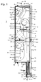
- the ventilation device contains a thermally separated housing 2 with a Clamping frame 4, which is preferably circumferential and / or four-sided for connection to a facade or window structure or the like.
- the Ventilation units can be used as floor, parapet, ceiling or panel units reach. Except for the air ducts, blowers and others to be explained Installation components, the inside of the housing is essentially completely made of insulating material 6 provided for heat and / or sound insulation.
- the built-in ventilation unit is located between an exterior room 7 and a room 8 of a building. Facing the room 8, the ventilation device contains an inner lining 10 and the Outside space 7 facing outside weather protection slats 12 or like.
- the housing 2 contains an inflow opening 14 for on the outside Fresh air or supply air, which according to the arrows 16 by a supply air blower 18 a supply air duct 20, 22 is sucked in and to an outflow opening 23 on the inside of the room is promoted.
- a supply air filter 24 is arranged in the supply air duct 20 in front of the supply air blower 18, which enables air filtering, preferably from EU 2 up to pollen filters.
- an exhaust air duct 26, 28 is made in the housing 2 or its insulating material 6 the air 8 to be discharged is provided according to the arrows 30.
- the exhaust air 30 is through an upper opening 32 of the housing 2 as shown in the drawing and one of the Filter 34 associated opening 32 by means of a arranged in the interior of the housing Exhaust fan 36 sucked in over the following down according to the drawing Channel 28 to reach the outside through an outflow opening 38.
- a heat exchanger 40 Based on the longitudinal extent of the housing 2 parallel to the outer wall 39 thereof, is at least approximately in the middle of the housing 2 a heat exchanger 40 provided which is the preferred way as a cross-flow plate heat exchanger is trained and enables energy recovery from the exhaust air for the supply air. For safe, consistent separation of the supply air duct 20 from the exhaust air duct 26 there is an intermediate wall 42, 43 between these channels, which is connected to the heat exchanger 40 is tightly connected. Below the heat exchanger 40 is a drip pan 44 arranged for condensate.
- the drip tray 44 there is a in particular as a fleece element 45 for airtight conduction of the Exhaust air trapped condensate in the area of the supply air duct 20 to the collecting tray 44 or to the element or fleece 45, the intermediate wall leading downwards 42 and 43, preferably in combination with applied webs, is done reliably separation of the exhaust air from the supply air.
- the heat exchanger 40 is in its essentially vertically arranged plates formed such that its shafts for the exhaust air are open at the bottom and thus condensate accumulating in the below Arranged collecting tray 44 can get or drip.
- the condensate reaches the area of the supply air duct 20 behind the Inflow opening 14.
- the housing 2 contains a further blower 46 in the region of the opening 32 which circulating air can be sucked in through the opening 32 according to arrow 48.
- the Another fan 46 is behind another opening 50 in the housing 2 or its Outer wall 39 arranged, with additional air circulating through the further opening 50 can be sucked in according to arrow 52.
- a closure element 54 which is designed in particular as a pivotable flap can according to the selectable Operating mode, the further opening 50 is closed or released.
- the closure element 54 is a preferably electrical one, not shown here Drive provided, which of the mentioned regulation and control unit is controllable.
- inlet opening 14 for supply air is assigned a closure element 56, which is also a pivotable flap that can be actuated by a drive is trained.
- outflow opening 38 for exhaust air is a turn preferably assigned as a flap closure element 58, which over a drive can be operated and according to the selected operating mode via the control and control unit is controllable.
- At least one fan is in Dependency of the wind suction and the wind pressure regulated.
- the invention from Suction and wind pressure-dependent regulation is described below in connection with the Supply air blower 18 explains and is analogous to the other blowers 36 and 46 intended.
- a differential pressure measurement is carried out by means of the sensors 60, 61 and a the corresponding signal is in particular a logic element of the regulating and control unit supplied for speed control of the supply air fan 18.
- at least one approximately constant volume flow preferably within a predetermined Print window or print area, automatically adjusted.
- the supply air blower 18 is independent of the wind suction and / or Wind pressure, which prevails in the outer space 7 or on the facade, and it is a constant heating due to the essentially constant volume flow and / or cooling performance guaranteed.
- the second sensor 61 in the supply air duct 22 can preferably be in the region of a particularly below a further sensor 61 is arranged in the outlet opening 64 of the convector 62 be for speed control, in particular of the supply air fan 18.
- a convector 62 In the area of the outflow opening 23 and expediently below it is a convector 62 movably arranged.
- a base plate 63 is provided, below the convector 62 the outlet opening 64 is present.
- the convector 62 at least partially within a pack, not shown here arranged from suitable insulation material.
- the convector flows through the supply air conveyed by the supply air blower 18 from the top to the top below through the convector 62 and enters the room 8 through the outlet opening 64.
- a second position of the convector is indicated by means of lines 66, which in this case at least partially moved towards space 8, namely about an axis of rotation 68 is pivoted.
- the convector 62 is on the base plate 63 by means of a bearing around the Axis of rotation 68 pivotally mounted.
- the outflow opening 23 is preferably closed automatically and / or by means of a shut-off device 69.
- the convector can flow through the opening 64 Air in the room 8 flows through from bottom to top in accordance with the arrows 70 get back into room 8.
- the shut-off device is advantageously connected to the Convector 62 coupled so that when moving and / or pivoting the convector 62 to the second position the flow path from the supply air duct 62 to the outside or is blocked off by the convector 62.
- the convector 62 is in the first Position, the shut-off device 69 gives the flow path from the supply air duct 22 to and through the convector 62 free.
- the convector 62 is advantageously in the region of the outflow opening 23
- Supply air duct 22 is arranged, preferably below the housing 2.
- the convector 22 is at least partially within the Housing 2 arranged, likewise in the region of the outflow opening 23.
- At at least partial or complete arrangement of the convector 22 in the housing 2 this contains at least one opening and / or one in the region of the convector 62 Shut-off device in such a way that in the first position that demanded by the supply air blower 18 Air is conveyed through the convector 62, while in the second position the room air as a result of convection, flows through the convector 62 and through said Opening of the housing can flow into the room.
- the convector at least partially in Housing 2 may be fixed, wherein by means of said shut-off device in the first position of the same the flow path of the air flowing out of the housing is released by the convector 62 while in the second position the room air flows through the convector 62 in the opposite direction due to the convection and through said at least one opening, which is hereby opened, flows.
- the convector 62 is a heating or cooling element with a one, two, three or four-wire system, whereby according to the predetermined by means of the regulating and control unit Operating mode via the supplied medium heat or cold is supplied.
- the inner one The casing 10 is at a predetermined distance from the rear wall 71 of the housing 2 arranged so that there is a channel 72 through which in the second position the air that rises as a result of convection flow upwards and through accordingly trained openings of the inner panel 10 can flow into the room 8. How can be seen, the inner lining 10 also covers the convector 62.
- the distance between the inner cladding 10 to the housing 2 or to the convector 62 is predefined in such a way that in the second position thereof according to line 66, the outflowing air or rising thermals according to arrows 70 essentially unimpeded from the Convector 2 exits and enters channel 72.
- To convector 62 in the first or Moving or pivoting the second position is one on the base plate and / or on attached to the underside of the housing provided drive unit 74, which accordingly the desired operating mode controlled by the regulating and control unit becomes.
- the convector 62 there is a free passage for the air Collection tray 76 arranged for condensate or fastened to the base plate 63.
- the Collecting trough 76 contains a lateral outlet connection 78 for the condensate.
- a flow wedge 80 is arranged above the outlet opening 64 and correspondingly further up a flow wedge 82 to the rising thermals in the room 8 to steer.
- a temperature sensor 83 connected downstream of the convector 62 The temperature of the outflowing air is recorded and as a measured variable of the regulating and control unit supplied to the air temperature taking into account variable specifications influence.
- FIG. 2 shows a section through the ventilation device along section line II according to FIG. 1.
- An air duct 84 adjoins the blower 46 and extends in the longitudinal direction of the Housing extends up to a mixing chamber 86 in which the through the air channel 84th Pumped air can mix with the supply air according to arrow 16.
- a functional unit is created, which is fundamentally exclusive is designed as a recirculation unit.
- the mixing chamber 86 opens into the outflow opening 23.
- the functional unit is therefore a recirculation unit with additional Fresh air intake trained.
- the convector 62 forms a heating or cooling body, which is designed here as a four-wire system with four connections 88. To this Connections 88 are movable and / or flexible lines according to the dashed line Line 90 connected for the heating or cooling medium.
- blower element 92 is connected downstream of the further blower 46, which is designed in particular as a pivotable flap.
- the closure element 92 is preferably designed automatically to reverse flow when the fan 46 is switched off to prevent through the air duct 84. If necessary, a drive unit for the closure element 92 to be provided via the regulating and control unit according to the selected operating mode to release the air duct 84 or shut off.
- the air duct 84 is arranged adjacent to the one longitudinal wall 94, specifically in the Insulating material 6, which has a predetermined thickness to achieve the longitudinal wall 94 has the desired insulation effect. Is located near the other longitudinal wall 96 likewise in the insulating material 6 the supply air duct 22 leading to the mixing chamber 86 is adjacent Exhaust air duct 26 and adjacent to air duct 84 are located in insulating material 6 to this in the direction of the other longitudinal wall 96, the heat exchanger 40 is arranged.
- bypass duct 98 in Extension of the exhaust air duct 26 is a bypass duct 98 with a bypass element 100 arranged.
- the bypass element is expediently designed as a pivotable flap and can be actuated by means of a preferably electrical drive unit.
- the drive unit can be regulated or controlled via the regulating and control unit. Is by means of Bypass element enables the connection of the exhaust air duct 26 to the bypass duct 98, so the heat exchanger 40 is bypassed and the exhaust air is directly from the exhaust fan 36 sucked in.
- the operating mode thus made, internal heat exchanger bypass is selected when the fresh air is cooler than the room air, so that with the fresh air the room 8, for example, can be cooled in an energetically favorable manner for night cooling should.
- the bypass control according to the invention thus makes it more energy-efficient Operation enables.
- the ventilation device instead of the previously described Arrangement according to which the fans 36, 18 and 46 are essentially vertically one above the other, can also be arranged such that the longitudinal axis of the Ventilation device is aligned essentially horizontally and the blowers mentioned lie side by side.
- the ventilation unit is compared to Figures 1 and 2 thus arranged rotated by 90 °. In this configuration, it contains Housing 2 in the region of the mixing chamber 86 in the longitudinal wall, which according to FIG in front of or behind the plane of the drawing, the one indicated by dash-dotted lines Outflow opening 23 '.
- this outflow opening 23 ' arranged the convector, the inner panel 10 corresponding to Coverage of the convector is formed and also the outlet openings for the ascending thermal with free convection in the second position of the convector having.
- FIG 3 is a top view of the ventilation device in viewing direction III according to Figure 2 shown.
- the outer weather protection slats 12, the four-sided clamping frame 4 and the suction opening 32 for the recirculating air and the exhaust air can be clearly seen.
- the lower mixed air chamber 86 is indicated by dashed lines.
- the inner lining 10 of the housing 2 is U-shaped, between the rear wall 71 and the inner panel 10 a sufficient large distance from the formation of the above-described channel 72 for the ascending thermal is available.
Landscapes
- Engineering & Computer Science (AREA)
- Chemical & Material Sciences (AREA)
- Combustion & Propulsion (AREA)
- Mechanical Engineering (AREA)
- General Engineering & Computer Science (AREA)
- Air-Flow Control Members (AREA)
- Other Air-Conditioning Systems (AREA)
- Control Of Motors That Do Not Use Commutators (AREA)
- Input Circuits Of Receivers And Coupling Of Receivers And Audio Equipment (AREA)
- Compressor (AREA)
- Ventilation (AREA)
Applications Claiming Priority (4)
| Application Number | Priority Date | Filing Date | Title |
|---|---|---|---|
| DE10257325 | 2002-12-06 | ||
| DE10257325 | 2002-12-06 | ||
| DE10307047 | 2003-02-20 | ||
| DE2003107047 DE10307047A1 (de) | 2003-02-20 | 2003-02-20 | Lüftungsgerät |
Publications (3)
| Publication Number | Publication Date |
|---|---|
| EP1426706A2 true EP1426706A2 (fr) | 2004-06-09 |
| EP1426706A3 EP1426706A3 (fr) | 2006-05-17 |
| EP1426706B1 EP1426706B1 (fr) | 2008-08-20 |
Family
ID=32313576
Family Applications (1)
| Application Number | Title | Priority Date | Filing Date |
|---|---|---|---|
| EP03025179A Expired - Lifetime EP1426706B1 (fr) | 2002-12-06 | 2003-11-04 | Dispositif de ventilation |
Country Status (3)
| Country | Link |
|---|---|
| EP (1) | EP1426706B1 (fr) |
| AT (1) | ATE405800T1 (fr) |
| DE (1) | DE50310350D1 (fr) |
Cited By (3)
| Publication number | Priority date | Publication date | Assignee | Title |
|---|---|---|---|---|
| EP1701106A3 (fr) * | 2005-02-15 | 2007-11-14 | Lg Electronics Inc. | Système de ventilation |
| DE202010004803U1 (de) * | 2010-04-09 | 2011-09-02 | Stiebel Eltron Gmbh & Co. Kg | Lüftungsanlage und Luftfilter |
| EP4379281A1 (fr) * | 2022-11-30 | 2024-06-05 | Vero Duco N.V. | Système de ventilation équilibré hygiénique et procédé de commande d'un tel système de ventilation |
Citations (1)
| Publication number | Priority date | Publication date | Assignee | Title |
|---|---|---|---|---|
| DE19539811C2 (de) | 1995-10-26 | 2000-02-24 | Altura Leiden Holding | Lüftungsvorrichtung |
Family Cites Families (4)
| Publication number | Priority date | Publication date | Assignee | Title |
|---|---|---|---|---|
| DE3632268A1 (de) * | 1986-09-23 | 1988-04-07 | Alois Laternser | Verfahren und vorrichtung zum belueften eines raumes |
| DE19810357A1 (de) * | 1998-03-10 | 1999-09-16 | Olsberg Hermann Everken Gmbh | Lüftungs-Heizvorrichtung |
| DE19911645A1 (de) * | 1999-03-16 | 2000-09-21 | Volkswagen Ag | Heizvorrichtung zur Erwärmung eines Luftstroms |
| DE20114892U1 (de) * | 2001-05-11 | 2002-01-17 | FensterSystemLüftung GmbH & Co. KG, 68199 Mannheim | Lüftungssystem zum dezentralen Belüften von Räumen in Gebäuden |
-
2003
- 2003-11-04 DE DE50310350T patent/DE50310350D1/de not_active Expired - Lifetime
- 2003-11-04 EP EP03025179A patent/EP1426706B1/fr not_active Expired - Lifetime
- 2003-11-04 AT AT03025179T patent/ATE405800T1/de not_active IP Right Cessation
Patent Citations (1)
| Publication number | Priority date | Publication date | Assignee | Title |
|---|---|---|---|---|
| DE19539811C2 (de) | 1995-10-26 | 2000-02-24 | Altura Leiden Holding | Lüftungsvorrichtung |
Cited By (4)
| Publication number | Priority date | Publication date | Assignee | Title |
|---|---|---|---|---|
| EP1701106A3 (fr) * | 2005-02-15 | 2007-11-14 | Lg Electronics Inc. | Système de ventilation |
| DE202010004803U1 (de) * | 2010-04-09 | 2011-09-02 | Stiebel Eltron Gmbh & Co. Kg | Lüftungsanlage und Luftfilter |
| EP4379281A1 (fr) * | 2022-11-30 | 2024-06-05 | Vero Duco N.V. | Système de ventilation équilibré hygiénique et procédé de commande d'un tel système de ventilation |
| BE1031084B1 (nl) * | 2022-11-30 | 2024-06-24 | Vero Duco | Hygienisch balansventilatiesysteem en werkwijze voor het aansturen van een dergelijke ventilatiesysteem |
Also Published As
| Publication number | Publication date |
|---|---|
| ATE405800T1 (de) | 2008-09-15 |
| EP1426706B1 (fr) | 2008-08-20 |
| DE50310350D1 (de) | 2008-10-02 |
| EP1426706A3 (fr) | 2006-05-17 |
Similar Documents
| Publication | Publication Date | Title |
|---|---|---|
| EP2405207B1 (fr) | Dispositif de climatisation intégrable au plafond | |
| DE3112394C2 (fr) | ||
| DE3411053A1 (de) | Klimatisierungsvorrichtung fuer fahrzeuge | |
| DE3006318A1 (de) | Lueftervorrichtung | |
| EP2573478B1 (fr) | Appareil d'aération avec récupération de chaleur | |
| DE102010042948B4 (de) | Dezentrale Raumlüftungsvorrichtung mit Wärmerückgewinnung | |
| WO2023089137A1 (fr) | Air de circulation et système de module d'air de circulation | |
| DE102010042950A1 (de) | Dezentrale Raumlüftungsvorrichtung mit Wärmerückgewinnung | |
| DE19539811C2 (de) | Lüftungsvorrichtung | |
| EP1522799B1 (fr) | Méthode et installation pour la climatisation d'une pièce | |
| DE2149906C3 (de) | Kühlvorrichtung für einen Antriebsmotor eines Panzerfahrzeuges | |
| EP1426706B1 (fr) | Dispositif de ventilation | |
| DE102009015479A1 (de) | Dezentrales Zu-und Abluftgerät sowie Verfahren zum dezentralen Lüften und/oder Klimatisieren | |
| DE10307047A1 (de) | Lüftungsgerät | |
| DE102005011222A1 (de) | Lüftungsanlage | |
| DE3942017C2 (fr) | ||
| DE3341827A1 (de) | Lueftungssystem fuer die raeume von gebaeuden | |
| EP1348911B1 (fr) | Dispositif de climatisation d'air pour la commande du chauffage et de l'humidification dans une enceinte fermée | |
| DE3248227A1 (de) | Umlaufende einfassung fuer tueren oder fenster, sowie kastenbauteil, insbesondere rolladenkasten, zur verwendung oberhalb der einfassung | |
| DE2706593C2 (de) | Vorrichtung zum Beheizen, Belüften und Kühlen von großen Fahrzeugräumen | |
| DE19907844C2 (de) | Lüftungsgerät für die Räume von Gebäuden | |
| CH697823B1 (de) | Einrichtung zum Klimatisieren eines Raumes. | |
| EP3916312B1 (fr) | Dispositif de refroidissement et procédé de refroidissement d'une pièce | |
| DE29518108U1 (de) | Gerät zur Belüftung von Räumen | |
| DE202008014287U1 (de) | Hybride Raumlüftungsvorrichtung |
Legal Events
| Date | Code | Title | Description |
|---|---|---|---|
| PUAI | Public reference made under article 153(3) epc to a published international application that has entered the european phase |
Free format text: ORIGINAL CODE: 0009012 |
|
| AK | Designated contracting states |
Kind code of ref document: A2 Designated state(s): AT BE BG CH CY CZ DE DK EE ES FI FR GB GR HU IE IT LI LU MC NL PT RO SE SI SK TR |
|
| AX | Request for extension of the european patent |
Extension state: AL LT LV MK |
|
| RAP1 | Party data changed (applicant data changed or rights of an application transferred) |
Owner name: ERWIN MUELLER GMBH |
|
| PUAL | Search report despatched |
Free format text: ORIGINAL CODE: 0009013 |
|
| AK | Designated contracting states |
Kind code of ref document: A3 Designated state(s): AT BE BG CH CY CZ DE DK EE ES FI FR GB GR HU IE IT LI LU MC NL PT RO SE SI SK TR |
|
| AX | Request for extension of the european patent |
Extension state: AL LT LV MK |
|
| RIC1 | Information provided on ipc code assigned before grant |
Ipc: F24F 12/00 20060101AFI20040316BHEP Ipc: F24F 7/08 20060101ALI20060329BHEP |
|
| 17P | Request for examination filed |
Effective date: 20060718 |
|
| AKX | Designation fees paid |
Designated state(s): AT BE BG CH CY CZ DE DK EE ES FI FR GB GR HU IE IT LI LU MC NL PT RO SE SI SK TR |
|
| GRAP | Despatch of communication of intention to grant a patent |
Free format text: ORIGINAL CODE: EPIDOSNIGR1 |
|
| GRAS | Grant fee paid |
Free format text: ORIGINAL CODE: EPIDOSNIGR3 |
|
| GRAA | (expected) grant |
Free format text: ORIGINAL CODE: 0009210 |
|
| AK | Designated contracting states |
Kind code of ref document: B1 Designated state(s): AT BE BG CH CY CZ DE DK EE ES FI FR GB GR HU IE IT LI LU MC NL PT RO SE SI SK TR |
|
| REG | Reference to a national code |
Ref country code: GB Ref legal event code: FG4D Free format text: NOT ENGLISH |
|
| REG | Reference to a national code |
Ref country code: CH Ref legal event code: NV Representative=s name: SCHNEIDER FELDMANN AG PATENT- UND MARKENANWAELTE Ref country code: CH Ref legal event code: EP |
|
| REG | Reference to a national code |
Ref country code: IE Ref legal event code: FG4D Free format text: LANGUAGE OF EP DOCUMENT: GERMAN |
|
| REF | Corresponds to: |
Ref document number: 50310350 Country of ref document: DE Date of ref document: 20081002 Kind code of ref document: P |
|
| PG25 | Lapsed in a contracting state [announced via postgrant information from national office to epo] |
Ref country code: ES Free format text: LAPSE BECAUSE OF FAILURE TO SUBMIT A TRANSLATION OF THE DESCRIPTION OR TO PAY THE FEE WITHIN THE PRESCRIBED TIME-LIMIT Effective date: 20081201 Ref country code: NL Free format text: LAPSE BECAUSE OF FAILURE TO SUBMIT A TRANSLATION OF THE DESCRIPTION OR TO PAY THE FEE WITHIN THE PRESCRIBED TIME-LIMIT Effective date: 20080820 |
|
| PG25 | Lapsed in a contracting state [announced via postgrant information from national office to epo] |
Ref country code: SI Free format text: LAPSE BECAUSE OF FAILURE TO SUBMIT A TRANSLATION OF THE DESCRIPTION OR TO PAY THE FEE WITHIN THE PRESCRIBED TIME-LIMIT Effective date: 20080820 Ref country code: FI Free format text: LAPSE BECAUSE OF FAILURE TO SUBMIT A TRANSLATION OF THE DESCRIPTION OR TO PAY THE FEE WITHIN THE PRESCRIBED TIME-LIMIT Effective date: 20080820 |
|
| PGFP | Annual fee paid to national office [announced via postgrant information from national office to epo] |
Ref country code: AT Payment date: 20081128 Year of fee payment: 6 |
|
| REG | Reference to a national code |
Ref country code: IE Ref legal event code: FD4D |
|
| PG25 | Lapsed in a contracting state [announced via postgrant information from national office to epo] |
Ref country code: IE Free format text: LAPSE BECAUSE OF FAILURE TO SUBMIT A TRANSLATION OF THE DESCRIPTION OR TO PAY THE FEE WITHIN THE PRESCRIBED TIME-LIMIT Effective date: 20080820 Ref country code: DK Free format text: LAPSE BECAUSE OF FAILURE TO SUBMIT A TRANSLATION OF THE DESCRIPTION OR TO PAY THE FEE WITHIN THE PRESCRIBED TIME-LIMIT Effective date: 20080820 Ref country code: BG Free format text: LAPSE BECAUSE OF FAILURE TO SUBMIT A TRANSLATION OF THE DESCRIPTION OR TO PAY THE FEE WITHIN THE PRESCRIBED TIME-LIMIT Effective date: 20081120 |
|
| PG25 | Lapsed in a contracting state [announced via postgrant information from national office to epo] |
Ref country code: SK Free format text: LAPSE BECAUSE OF FAILURE TO SUBMIT A TRANSLATION OF THE DESCRIPTION OR TO PAY THE FEE WITHIN THE PRESCRIBED TIME-LIMIT Effective date: 20080820 Ref country code: CZ Free format text: LAPSE BECAUSE OF FAILURE TO SUBMIT A TRANSLATION OF THE DESCRIPTION OR TO PAY THE FEE WITHIN THE PRESCRIBED TIME-LIMIT Effective date: 20080820 Ref country code: PT Free format text: LAPSE BECAUSE OF FAILURE TO SUBMIT A TRANSLATION OF THE DESCRIPTION OR TO PAY THE FEE WITHIN THE PRESCRIBED TIME-LIMIT Effective date: 20090120 Ref country code: RO Free format text: LAPSE BECAUSE OF FAILURE TO SUBMIT A TRANSLATION OF THE DESCRIPTION OR TO PAY THE FEE WITHIN THE PRESCRIBED TIME-LIMIT Effective date: 20080820 |
|
| BERE | Be: lapsed |
Owner name: ERWIN MULLER G.M.B.H. Effective date: 20081130 |
|
| PLBE | No opposition filed within time limit |
Free format text: ORIGINAL CODE: 0009261 |
|
| STAA | Information on the status of an ep patent application or granted ep patent |
Free format text: STATUS: NO OPPOSITION FILED WITHIN TIME LIMIT |
|
| PG25 | Lapsed in a contracting state [announced via postgrant information from national office to epo] |
Ref country code: MC Free format text: LAPSE BECAUSE OF NON-PAYMENT OF DUE FEES Effective date: 20081130 |
|
| PGFP | Annual fee paid to national office [announced via postgrant information from national office to epo] |
Ref country code: CH Payment date: 20090225 Year of fee payment: 6 |
|
| 26N | No opposition filed |
Effective date: 20090525 |
|
| GBPC | Gb: european patent ceased through non-payment of renewal fee |
Effective date: 20081120 |
|
| PG25 | Lapsed in a contracting state [announced via postgrant information from national office to epo] |
Ref country code: EE Free format text: LAPSE BECAUSE OF FAILURE TO SUBMIT A TRANSLATION OF THE DESCRIPTION OR TO PAY THE FEE WITHIN THE PRESCRIBED TIME-LIMIT Effective date: 20080820 |
|
| PG25 | Lapsed in a contracting state [announced via postgrant information from national office to epo] |
Ref country code: IT Free format text: LAPSE BECAUSE OF FAILURE TO SUBMIT A TRANSLATION OF THE DESCRIPTION OR TO PAY THE FEE WITHIN THE PRESCRIBED TIME-LIMIT Effective date: 20080820 |
|
| REG | Reference to a national code |
Ref country code: FR Ref legal event code: ST Effective date: 20090731 |
|
| PG25 | Lapsed in a contracting state [announced via postgrant information from national office to epo] |
Ref country code: BE Free format text: LAPSE BECAUSE OF NON-PAYMENT OF DUE FEES Effective date: 20081130 |
|
| PG25 | Lapsed in a contracting state [announced via postgrant information from national office to epo] |
Ref country code: GB Free format text: LAPSE BECAUSE OF NON-PAYMENT OF DUE FEES Effective date: 20081120 |
|
| PG25 | Lapsed in a contracting state [announced via postgrant information from national office to epo] |
Ref country code: SE Free format text: LAPSE BECAUSE OF FAILURE TO SUBMIT A TRANSLATION OF THE DESCRIPTION OR TO PAY THE FEE WITHIN THE PRESCRIBED TIME-LIMIT Effective date: 20081120 |
|
| REG | Reference to a national code |
Ref country code: CH Ref legal event code: PL |
|
| PG25 | Lapsed in a contracting state [announced via postgrant information from national office to epo] |
Ref country code: LU Free format text: LAPSE BECAUSE OF NON-PAYMENT OF DUE FEES Effective date: 20081104 Ref country code: HU Free format text: LAPSE BECAUSE OF FAILURE TO SUBMIT A TRANSLATION OF THE DESCRIPTION OR TO PAY THE FEE WITHIN THE PRESCRIBED TIME-LIMIT Effective date: 20090221 Ref country code: CY Free format text: LAPSE BECAUSE OF FAILURE TO SUBMIT A TRANSLATION OF THE DESCRIPTION OR TO PAY THE FEE WITHIN THE PRESCRIBED TIME-LIMIT Effective date: 20080820 |
|
| PG25 | Lapsed in a contracting state [announced via postgrant information from national office to epo] |
Ref country code: TR Free format text: LAPSE BECAUSE OF FAILURE TO SUBMIT A TRANSLATION OF THE DESCRIPTION OR TO PAY THE FEE WITHIN THE PRESCRIBED TIME-LIMIT Effective date: 20080820 Ref country code: AT Free format text: LAPSE BECAUSE OF NON-PAYMENT OF DUE FEES Effective date: 20091104 |
|
| PG25 | Lapsed in a contracting state [announced via postgrant information from national office to epo] |
Ref country code: LI Free format text: LAPSE BECAUSE OF NON-PAYMENT OF DUE FEES Effective date: 20091130 Ref country code: CH Free format text: LAPSE BECAUSE OF NON-PAYMENT OF DUE FEES Effective date: 20091130 Ref country code: GR Free format text: LAPSE BECAUSE OF FAILURE TO SUBMIT A TRANSLATION OF THE DESCRIPTION OR TO PAY THE FEE WITHIN THE PRESCRIBED TIME-LIMIT Effective date: 20081121 |
|
| PGFP | Annual fee paid to national office [announced via postgrant information from national office to epo] |
Ref country code: DE Payment date: 20101220 Year of fee payment: 8 |
|
| PG25 | Lapsed in a contracting state [announced via postgrant information from national office to epo] |
Ref country code: FR Free format text: LAPSE BECAUSE OF NON-PAYMENT OF DUE FEES Effective date: 20081130 |
|
| REG | Reference to a national code |
Ref country code: DE Ref legal event code: R119 Ref document number: 50310350 Country of ref document: DE Effective date: 20120601 |
|
| PG25 | Lapsed in a contracting state [announced via postgrant information from national office to epo] |
Ref country code: DE Free format text: LAPSE BECAUSE OF NON-PAYMENT OF DUE FEES Effective date: 20120601 |