EP1426984B1 - Transformatoranordnung eines Mikrowellenofens, ihr Herstellungsverfahren und Mikrowellenofen mit einer solchen Transformatoranordnung - Google Patents
Transformatoranordnung eines Mikrowellenofens, ihr Herstellungsverfahren und Mikrowellenofen mit einer solchen Transformatoranordnung Download PDFInfo
- Publication number
- EP1426984B1 EP1426984B1 EP03256910A EP03256910A EP1426984B1 EP 1426984 B1 EP1426984 B1 EP 1426984B1 EP 03256910 A EP03256910 A EP 03256910A EP 03256910 A EP03256910 A EP 03256910A EP 1426984 B1 EP1426984 B1 EP 1426984B1
- Authority
- EP
- European Patent Office
- Prior art keywords
- transformer
- container
- base part
- transformer assembly
- microwave oven
- Prior art date
- Legal status (The legal status is an assumption and is not a legal conclusion. Google has not performed a legal analysis and makes no representation as to the accuracy of the status listed.)
- Expired - Lifetime
Links
Images






Classifications
-
- H—ELECTRICITY
- H05—ELECTRIC TECHNIQUES NOT OTHERWISE PROVIDED FOR
- H05B—ELECTRIC HEATING; ELECTRIC LIGHT SOURCES NOT OTHERWISE PROVIDED FOR; CIRCUIT ARRANGEMENTS FOR ELECTRIC LIGHT SOURCES, IN GENERAL
- H05B6/00—Heating by electric, magnetic or electromagnetic fields
- H05B6/64—Heating using microwaves
- H05B6/6402—Aspects relating to the microwave cavity
-
- H—ELECTRICITY
- H01—ELECTRIC ELEMENTS
- H01F—MAGNETS; INDUCTANCES; TRANSFORMERS; SELECTION OF MATERIALS FOR THEIR MAGNETIC PROPERTIES
- H01F27/00—Details of transformers or inductances, in general
- H01F27/08—Cooling; Ventilating
- H01F27/10—Liquid cooling
- H01F27/12—Oil cooling
-
- H—ELECTRICITY
- H01—ELECTRIC ELEMENTS
- H01F—MAGNETS; INDUCTANCES; TRANSFORMERS; SELECTION OF MATERIALS FOR THEIR MAGNETIC PROPERTIES
- H01F27/00—Details of transformers or inductances, in general
- H01F27/02—Casings
- H01F27/025—Constructional details relating to cooling
-
- H—ELECTRICITY
- H01—ELECTRIC ELEMENTS
- H01F—MAGNETS; INDUCTANCES; TRANSFORMERS; SELECTION OF MATERIALS FOR THEIR MAGNETIC PROPERTIES
- H01F27/00—Details of transformers or inductances, in general
- H01F27/06—Mounting, supporting or suspending transformers, reactors or choke coils not being of the signal type
Definitions
- the present invention relates to a transformer assembly for microwave ovens, a method for manufacturing the same, and a microwave oven equipped with the same.
- a conventional transformer for microwave ovens increases a voltage of a power source, and includes a core and primary and secondary windings wound around the core.
- the transformer is installed in an electrical components area, partitioned from a cooking chamber, together with other electrical components such as a high-voltage capacitor and a cooling fan.
- the transformer inherently generates heat by resistance of the coils and generation of eddy current due to variation of magnetic flux density of the cores.
- the heat is removed by a cooling device having a fan and a fan motor in an air-cooling manner.
- the transformer Because the transformer generates vibration and noise during its operation, the transformer is provided with a separate rubber cushion to overcome the above problems.
- the cooling procedure for the transformer which involves only air cooling, has a low cooling efficiency, an operational efficiency of the transformer is decreased. Consequently, the components, such as the core and the coils, must be manufactured with large surface areas to compensate for the decrease of operational efficiency, thereby increasing production costs. In addition, because vibration-absorbing elements such as the rubber cushions are required to absorb the vibration and noise, the production cost is further increased.
- the conventional transformer is immersed in a varnish solution to form a thin film on outer surfaces of the transformer during the manufacturing process, thereby increasing production cost and manufacturing time. Furthermore, because insulating material is required to prevent electric leakage from the transformer mounted on a microwave oven, labor costs are increased.
- US-A-3819899 discloses a microwave oven provided with a water tight container and a lid which together constitute a first structure unit for the microwave oven, said unit comprising all electrical components of the oven, including the magnetron and its supply circuit.
- the container can be filled with oil, paraffin or the like for cooling purposes.
- JP-A-11016740 discloses an oil-immersed transformer having a cylindrical case which is provided with a corrugated heat radiating surface as a side face that extends from the upper edge to the lower edge of the case.
- EP-A-0783239 discloses a high voltage transformer of a microwave oven which is directly mounted to a panel of the oven using screws which pass through the panel and into holes in the core of the transformer.
- US-A-4085395 discloses a high voltage transformer package, the case of which is filled with a dielectric liquid.
- the present invention aims to provide a transformer assembly for a microwave oven having many advantages, including any one or more of: being efficiently cooled by a cooling material; being miniaturized, lightweight, and having reduced production costs by reducing the sizes of associated components; having improved reliability by reducing vibration and noise during operation; and being efficiently and firmly mounted on a microwave oven with minimal installation space, resulting in miniaturization of the microwave oven and simplification of fabrication.
- a transformer assembly for use with a microwave oven having a magnetron, comprising: a transformer to in use apply voltage to the magnetron of the microwave oven; a container receiving the transformer therein; and a cooling material contained in the container to cool the transformer; characterised in that: the container comprises corrugated sidewalls and is maintained in a vacuumed condition at its upper portion.
- the container is a base plate coupleable to the microwave oven; and a cover body coupled to the base plate, the cover body comprising said corrugated sidewalls.
- the base plate comprises: a base part defining a bottom of the container; and mounting parts outwardly extended from respective ends of the base part beyond the cover body of the container, the mounting parts having screw holes to in use fasten the mounting parts (to the microwave oven.
- the base plate comprises: a base part defining a bottom of the container; extension parts at respective ends of the base part, formed by bending each end of the base part downwardly; and mounting parts at respective ends of the extension parts, formed by bending the end of each extension part outwardly with the base part being separated from the mounting parts, to in use fasten the base plate to the microwave oven.
- the base plate comprises: a base part defining a bottom of the container; extension parts at respective ends of the base part, formed by bending each end of the base part downwardly; and mounting parts at respective ends of the extension parts, formed by bending the end of each extension part inwardly with the base part being separated from the mounting parts), to in use fasten the base plate to the microwave oven.
- the transformer and the base plate are attached to each other by spot welding.
- the cover body and the base plate are attached to each other by brazing.
- the transformer assembly comprises: a bracket attached to a surface of the container (12) to in use install the container (12) in the microwave oven.
- the bracket comprises: a base part attached the surface of the container; and mounting parts outwardly extending from respective ends of the base part to in use fasten the bracket to the microwave oven.
- the bracket comprises: a base part attached to the surface of the container; extension parts at respective ends of the base part, formed by bending each end of the base part downwardly; and mounting parts at respective ends of the extension parts, formed by bending the end of each extension part outwardly with the base part being separated from the mounting parts, to in use fasten the bracket to the microwave oven.
- the bracket comprises: a base part attached to the surface of the container; extension parts at respective ends of the base part, formed by bending each end of the base part downwardly; and mounting parts at respective ends of the extension parts, formed by bending the end of each extension part inwardly with the base part being separated from the mounting parts, to in use fasten the bracket to the microwave oven.
- the mounting parts respectively comprise fastening portions having screw holes to in use fasten the container to the microwave oven.
- the transformer, the surface of the container), and the bracket are attached to one another by spot welding.
- the container is made of aluminum or copper.
- the transformer assembly further comprises an input line; an output line; a primary winding of the transformer coupleable to an external power source via the input line; a secondary winding of the transformer to in use output electric current, transformed by electromagnetic induction caused by the primary winding, to the magnetron via the output line; and a terminal unit attached to the cover body to allow the input line and the output line to be connected to the external power source and the magnetron, respectively.
- the terminal unit has block terminals.
- the cooling material is mineral oil.
- the cooling material is a colloidal material.
- a microwave oven comprising a cooking chamber; an electrical components area isolated from the cooking chamber; a magnetron installed in the electrical components area to generate microwaves into the cooking chamber; and a transformer assembly including a transformer to apply voltage to the magnetron; wherein the transformer assembly is arranged as herein referred to.
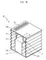
- FIG. 1A shows a transformer assembly 10 according to an embodiment of the present invention.
- the transformer assembly 10 includes a transformer 11 having a core 111 and coils 112 wound around the core 111, and a container 12 receiving the transformer 11 therein.
- the coils 112 include a lower primary winding connected to an electric power source and an upper secondary winding for outputting current transformed by electromagnetic induction caused by the lower primary winding.
- the container 12 is hermetically sealed, and includes a base plate 123 on which the transformer 11 is fixedly mounted, and an enveloping part coupled to the base plate 123 to cover the transformer 12.
- the enveloping part includes a wall body 121 defining side surfaces of the container 12 and a top plate 122.
- the tubular wall body 121 is shaped as a cylinder or as a polygon, and has corrugated surface s to efficiently radiate heat and accommodate thermal expansion.
- the corrugated surface has at least two points having different distances from the center of the container 12. That is, the wall body 121 efficiently radiates resistance heat generated from the coils 112 and resistance heat generated by eddy current on the core 111 during operation of the transformer 11.
- the container 12 may be made of copper or aluminum, which have excellent properties for efficiently radiating heat generated from the transformer 11 and for moldability, aluminum is lower in cost and weight.
- the container 12 contains non-conductive oil 105 as a liquid for cooling the transformer 11 housed within the container 12.
- non-conductive oil 105 serving as the cooling liquid
- mineral oil minimizes environmental pollution and harmful effects on the human body.
- oil There is no requirement to use oil as the cooling liquid.
- Non-conductive liquid other than oil, and colloidal materials such as sols or gels, may be used as the cooling liquid.
- the cooling liquid such as the non-conductive oil and the colloidal material, is considerably advantageous in that the cooling liquid absorbs vibration and noise generated from the transformer 11, thereby reducing vibration and noise transmitted outside the transformer 11 during operation of the transformer 11.
- the non-conductive oil 105 is supplied to the container 12 such that a heating portion of the transformer 11 is submerged in the oil. Accordingly, the oil 105 must be supplied to the container 12 in an amount sufficient to submerge the coils 112 in the oil 105, and both the coils 112 and the core 111 may be submerged in the oil. The amount of the oil 105 is reduced as much as possible while maintaining cooling efficiency for the transformer 11 by supplying the oil 105 to a level between, for example, the upper end of the core 111 and the upper end of the upper coil 112. The space 17 above the oil 105 is maintained in a vacuum state.
- the top plate 122 has an oil inlet 122a to allow the oil 105 to be injected into the container 12.
- the oil inlet 122a is needed for injection of the oil 105 into the container 12 when both the base plate 123 and the top plate 122 are coupled to the wall body 121 before placing the oil 105 in the container 12.
- the oil inlet 122a is dispensable.
- the transformer 11 has input lines 14 for supplying external low-voltage electric power to the transformer 11, and output lines 15 for outputting current transformed by electromagnetic induction.
- the input lines 14 and the output lines 15 are connected to the transformer 11 in the container 12 through the top plate 122. More specifically, the input lines 14 are connected to the primary winding of the coils 112, and the output line 15 are connected to the secondary winding of the coils 112. Therefore, the container 12 has through holes 16 to allow the input lines 14 and the output lines 15 to enter the container 12 therethrough.
- the through holes 16 are formed at the top plate 122 of the container 12, for example.
- the through holes 16, through which the input lines 14 and the output lines 15 respectively pass, are sealed with epoxy resin 18 to prevent the oil 105 from leaking from the container 12 and to make the container 12 airtight.
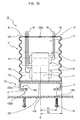
- FIG 1B shows the transformer assembly 10 according to an aspect of the present invention in which the top plate 122 of the container 12 has a terminal unit 19 to allow the input lines 14 and the output lines 15 to be connected to an external electric power source and to a magnetron (not shown), respectively.
- the terminal unit 19 allows the inside and the outside of the top plate 122 of the container 12 to be electrically connected to each other while maintaining the airtightness of the container 12. Accordingly, the transformer assembly 10 according to the aspect of the invention shown in Figure 1B is more advantageous than the transformer assembly 10 according to the aspect of the invention shown in Figure 1A because there is no necessity to perform an additional epoxy sealing procedure.
- the transformer assembly 10 according to an embodiment of the present invention, which is cooled by the cooling material 105, has been described heretofore with reference to Figures 1A and 1B.
- a structure for mounting the transformer assembly 10 on a microwave oven is now described with reference to Figures 2A through 3C.
- Figures 2A through 2D show structures for mounting the transformer assembly 10, as shown in Figures 1A and 1B, on a bottom plate 118 via a bracket 20-23.
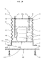
- FIG. 2A shows a bracket 20 for mounting the transformer assembly 10 on the bottom plate 118.
- the bracket 20 includes a base part 201 closely attached to the base plate 123 of the container 12, and mounting parts 202 outwardly extended from the ends of the base part 201.
- the mounting parts 202 are mounted on the bottom plate 118 of an electrical components area (not shown) of the microwave oven by a fastening unit. More specifically, the mounting parts 202 of the bracket 20 and the bottom plate 118 of the electrical components area of the microwave oven respectively have screw holes 2 and 118a and are fastened to each other using screws 119.
- brackets 21 and 22 for mounting the transformer assembly 10 on the bottom plate 118 of the electrical components area.
- the brackets 21 and 22 respectively include base parts 211 and 221 fixedly attached to the base plate 123 of the container 12, and mounting parts 212 and 222 having extension portions 212a and 222a downwardly bent at the peripheral edges of the base parts 211 and 221 and extended downwardly, and fastening portions 212b and 222b outwardly bent at ends of the extension portions 212a and 222a with a spacing between the fastening portions 212b and 222b and the base parts 211 and 221 and fastened to the bottom plate 118 of the electrical components area.
- the fastening portions 212b and 222b are formed with screw holes 2 to allow the fastening portions 212b and 222b to be fastened to the bottom plate 118 using screws 119.
- the fastening portions 212b and 222b are positioned under the wall body 121 of the container 12. That is, assuming that a distance between the center line "C" of the transformer 11 and a fastening point of the fastening portion 222b is R1, and a distance between the center line "C" of the transformer 11 and the wall body 121 is R2, R1 is less than R2.
- the mounting parts 202 and 212 Figures 2A and 2B occupy additional side space in addition to the space under the transformer assembly 10.
- the bracket 22 of Figure 2C is advantageous in that the space in the electrical components area can be efficiently used, and the size of the electrical components area can be reduced, thereby allowing miniaturization of the microwave oven.
- Figure 2D shows another bracket 23.
- the bracket 23 includes a base part 231 fixedly attached to the base plate 123 of the container 12, and mounting parts 232 having extension portions 232a downwardly bent at the peripheral edges of the base part 231 and extended downwardly, and fastening portions 232b inwardly bent at ends of the extension portions 232a, with a spacing between the fastening portion 232b and the base part 231, and fastened to the bottom plate 118 of the electrical components area.
- the transformer assembly 10 of Figure 2D has the same advantage as that of the transformer assembly 10 shown in Figure 2C.
- transformer assemblies 10 according to other aspects of the present invention in which the base plate 123 of the container 12 serves as a bracket to mount the transformer assembly 10 on the bottom plate 118 of the microwave oven.
- the base plate 123 includes a base part 301 serving as a bottom of the container 12, and mounting parts 302 outwardly extended from the base part 301 beyond the wall body 121 of the container 12 and having screw holes 2 to allow the mounting part 302 to be joined to the bottom plate 118 of the electrical components area using screws 119.
- the base plate 123 includes a base part 311 serving as a bottom of the container 12, and mounting parts 312 having extension portions 312a downwardly bent at the peripheral edges of the base part 311 and extended downwardly, and fastening portions 312b outwardly bent at ends of the extension portions 312a, with a spacing between the fastening portions 312b and the base part 311, and fastened to the bottom plate 118 of the electrical components area.
- the base plate 123 includes a base part 321 serving as a bottom of the container 12, and mounting parts 322 having extension portions 322a downwardly bent at the peripheral edges of the base part 321 and extended downwardly, and fastening portions 322b inwardly bent at ends of the extension portions 322a, with a spacing between the fastening portions 322b and the base part 321, and fastened to the bottom plate 118 of the electrical components area.
- the base plate 123 of the container 12 serves as a bracket
- the base plate 123 coupled to the wall body 121 of the container 12 is directly joined to the bottom plate 118 of the electrical components area
- the bracket 20, 21, 22, and 23 is attached to the base plate 123 of the container 12 and then joined to the bottom plate 118 of the electrical components area. Accordingly, because the base plate 123 of the container 12 is directly joined to the bottom plate 118 by a single procedure, reduction of cost of material and simplification of the production process are achieved, thereby improving productivity.
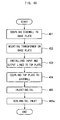
- FIGS 4A and 4B are flowcharts showing processes of manufacturing the transformer assembly 10 according to the present invention.
- the wall body 121 is first coupled to the base plate 123 of the container 12 at operation 401.
- the transformer 11 is mounted on the base plate 123 at operation 402. Thereafter, input lines 14 for supplying external electric power to the transformer 11, and output lines 15 for outputting current transformed by the transformer 11, are installed on the top plate 122 at operation 403.
- the top plate 122 is coupled to the wall body 121 at operation 404 to define the container 12, and oil 105 is injected into the container 12 at operation 405.
- operation 401 in which the wall body 121 is coupled to the base plate 123 is performed by a brazing process to assure the prevention of leakage of the oil 105 and the sealing ability of the container 12.
- the wall body 121 has a corrugated surface to increase the radiating surface thereof. More specifically, the tubular wall body 121, which includes a corrugated surface with at least two points having different distances from the center of the container 12, is prepared, and one end of the wall body 121 is coupled to the base plate 123.
- the mounting of the transformer 11 on the base plate 123 is carried out by spot welding to assure secure fixation.
- the transformer 11, the base plate 123, and the bracket 20, 21, 22, or 23 may all be combined together by spot welding.
- the bracket 20, 21, 22, or 23 is first attached to the base plate 123, and the transformer 11 and the integrated base plate 123 and bracket 20, 21, 22, or 23 are combined together at one time.
- the top plate 122 is formed with through holes 16
- installation of the input lines 14 and the output lines 15 on the top plate 122 is performed by introducing the input lines 14 and the output lines 15 into the container 12 through the through holes 16 and sealing the through holes 16 with epoxy resin 18.
- the top plate 122 is provided, at an outer surface thereof, with a terminal unit 19, as shown in Figure 1B, the installation of the input lines 14 and the output lines 15 on the top plate 122 may be performed by connecting the input lines 14 and the output lines 15 to the terminal unit 19.
- the top plate 122 with the oil inlet 122a is prepared, and the oil 105 is injected into the container 12 through the oil inlet 122a.
- the oil inlet 122a is sealed with epoxy resin 18 to maintain the container 12 in a hermetically sealed condition at operation 405a.
- the oil 105 is injected into the container 12 such that a level of the injected oil 105 is maintained between the top plate 122 of the container 12 and the upper end of the coils 112 of the transformer 11. That is, because the coils 112 are dominant heating elements among the elements of the transformer 11, the oil 105 is injected such that the coils 112 are completely submerged in the oil 105.
- the oil 105 may be supplied by an amount sufficient to submerge the core 111 in the oil 105. However, the oil 105 is supplied to a certain level between the upper end of the core 111 and the upper end of the coils 112 to reduce the amount of oil 105 as much as possible without deteriorating its cooling efficiency.
- operations 406, 407, and 408 are similar to operations 401, 402, and 403 of Figure 4A.
- the wall body 121 is first coupled to the base plate 123 at operation 406, and the transformer 11 is mounted on the base plate 123 at operation 407.
- the input lines 14 for supplying external power to the transformer 11, and the output lines 15 for outputting the current transformed by the transformer 11 to the magnetron, are installed through the top plate 122 at operation 408.
- the oil 105 is injected into the container 12 at operation 409, and the top plate 122 is coupled to the wall body 121 at operation 410.
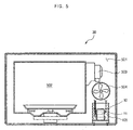
- Figure 5 shows a microwave oven 30 with the transformer assembly 10 as described above. More specifically, Figure 5 shows a microwave oven 30, in which the transformer assembly 10 shown in Figure 3C is mounted on a bottom plate 118 of an electrical components area 501 of the microwave oven 30. Operation of the microwave oven 30 according to the present invention is described below with reference to Figure 5.
- electric current which has been boosted in its voltage by electromagnetic induction, is supplied to a magnetron 503, and the magnetron 503 generates microwaves into a cooking chamber 502.
- the transformer 11 radiates high-temperature resistance heat generated from the coils 112 and the core 111.
- the heat radiated from the transformer 11 is immediately absorbed into mineral oil 105 contained in the container 12 of the transformer assembly 10 and then convected to the container 12, thereby causing the heat to be transmitted to the container 12. Because the wall body 121 of the container 12 has a large radiating area due to its corrugated surface, the container 12 of the transformer assembly 10 is efficiently cooled by external cool air introduced into the machine room 501 by a cooling fan 504. The cooling action for the transformer 11 is quickly and efficiently performed because the transformer 11 is surrounded by mineral oil 105, which serves as an efficient cooling medium.
- the transformer 11 since the heat absorbed by the mineral oil 105 is dispersed throughout the mineral oil 105 by convection of the oil 105 and transmitted to the container 12 having a relatively large radiating area, the heat transmitted to the container 12 can be efficiently and quickly removed by external air blown by the cooling fan 504. Accordingly, even though the transformer 11 may operate for a long period of time due to continuous operation of the microwave oven 30, the transformer 11 maintains a stable and constant output without loss of efficiency.
- the present invention provides a transformer assembly for a microwave oven, which has an improved operational efficiency due to its excellent cooling ability. Consequently, because the sizes of some of the components, such as the core and the coils, can be reduced by the improvement of the operational efficiency, production cost for the transformer assembly can be reduced. In addition, because high-density metal components are omitted and a low-density cooling material and container are used, it is possible to achieve miniaturization and weight reduction of the transformer assembly.
- the present invention provides a transformer assembly for a microwave oven, in which a transformer is securely installed in a container and the container is hermetically sealable by an improved assembly structure.
- non-conductive liquid is used as the cooling material
- the present invention provides an improved structure for efficiently installing a transformer assembly to a microwave oven, an improvement in productivity due to simplification of the assembly operation can be achieved.
- the space required to install the transformer assembly in an electrical components area of a microwave oven is significantly reduced, the remaining space in the machine room can be used for other applications, or the microwave oven can be miniaturized due to a reduction in size of the electrical components area.
Landscapes
- Engineering & Computer Science (AREA)
- Power Engineering (AREA)
- Physics & Mathematics (AREA)
- Electromagnetism (AREA)
- Constitution Of High-Frequency Heating (AREA)
- Control Of High-Frequency Heating Circuits (AREA)
- Transformer Cooling (AREA)
- Electric Ovens (AREA)
Claims (19)
- Transformatoranordnung zur Verwendung mit einem Mikrowellenherd, der ein Magnetron aufweist, mit:einem Transformator (11), um im Gebrauch Spannung an das Magnetron des Mikrowellenherds anzulegen;einem Behälter (12), der den Transformator (11) darin aufnimmt; undeinem Kühlmaterial (105), das in dem Behälter (12) enthalten ist, um den Transformator (11) zu kühlen;dadurch gekennzeichnet,dass:der Behälter (12) gewellte Seitenwandungen (121) aufweist, und an seinem oberen Abschnitt in einem Vakuum-Zustand gehalten ist.
- Transformatoranordnung nach Anspruch 1, wobei der Behälter (12) aufweist:eine Grundplatte (123), die mit dem Mikrowellenherd verkuppelbar ist; undeinen Abdeckhörper (121, 122), der an die Grundplatte (123) angekuppelt ist,wobei der Abdeckhörper (121, 122) die gewellten Seitenwandungen (121) auf weist.
- Transformatoranordnung nach Anspruch 2, wobei die Grundplatte (123) aufweist:einen Sockelteil (301), der eine Unterseite des Behälters (12) definiert; undMontageteile (302), die sich von jeweiligen Enden des Sockelteils (301)über den Abdecklörper (121, 122) des Behälters (12) hinaus nach außen erstrecken, und die Montageteile Schraubenlöcher (2) aufweisen, um bei der Verwendung die Montageteile (302) an dem Mikrowellenherd zu befestigen.
- Transformatoranordnung nach Anspruch 2, wobei die Grundplatte (123) aufweist:einen Sockelteil (311), der eine Unterseite des Behälters (12) definiert;Erweiterungsteile (312a) an jeweiligen Enden des Sockelteils (311), die durch ein nach unten Biegen jeden Endes des Sockelteils (311) gebildet sind; undMontageteile (312b) an jeweiligen Enden der Erweiterungsteile (312a), die durch ein nach außen Biegen des Endes von jedem Erweiterungsteil (312a) gebildet sind, wobei der Sockelteil (311) von den Montageteilen (312b) abgetrennt ist, um bei der Verwendung die Grundplatte (123) an dem Mikrowellenherd zu befestigen.
- Transformatoranordnung nach Anspruch 2, wobei die Grundplatte (123) aufweist:einen Sockelteil (321), der eine Unterseite des Behälters (12) definiert;Erweiterungsteile (322a) an jeweiligen Enden des Sockelteils (321), die durch ein nach unten Biegen jeden Endes des Sockelteils gebildet sind; undMontageteile (322b) an jeweiligen Enden der Erweiterungsteile (322a), die durch ein Einwärtsbiegen des Endes von jedem Erweiterungsteil (322a) gebildet sind,wobei der Sockelteil (321) von den Montageteilen (322a) abgetrennt ist, um bei der Verwendung die Grundplatte (123) an dem Mikrowellenherd zu befestigen.
- Transformatoranordnung nach einem der Ansprüche 2 bis 5, wobei der Transformator (11) und die Grundplatte (123) miteinander durch Punktschweßen verbunden sind.
- Transformatoranordnung nach einem der Ansprüche 2 bis 6, wobei der Abdeckkörper (121, 122) und die Grundplatte (123) miteinander durch Auflöten verbunden sind.
- Transformatoranordnung nach einem vorstehendem Anspruch, mit:einem Träger (20), der an einer Oberfläche des Behälters (12) befestigt ist, um bei der Verwendung den Behälter (12) in den Mikrowellenherd einzubauen.
- Transformatoranordnung nach Anspruch 8, wobei der Träger (20) aufweist:einen Sockelteil (201), der an der Oberfläche des Behälters (12) befestigt ist; undMontageteile (202), die sich von jeweiligen Enden des Sockelteils (201) nach außen erstrecken, um bei der Verwendung den Träger (20) an dem Mikrowellenherd zu befestigen.
- Transformatoranordnung nach Anspruch 8, wobei der Träger (20) aufweist:einen Sockelteil (211), der an der Oberfläche des Behälters (12) befestigt ist;Erweiterungsteile (212a) an jeweiligen Enden des Sockelteils (211), die durch ein nach unten Biegen von jedem Ende des Sockelteils (211) gebildet sind; undMontageteile (212b) an jeweiligen Enden der Erweiterungsteile (212a), die durch ein nach außen Biegen des Endes von jedem Erweiterungsteil (212) gebildet sind,wobei der Sockelteil (211) von den Montageteilen (212b) abgetrennt ist, um bei der Verwendung den Träger (20) an dem Mikrowellenherd zu befestigen.
- Transformatoranordnung nach Anspruch 8, wobei der Träger (20) aufweist:einen Sockelteil (231), der an der Oberfläche des Behälters (12) befestigt ist;Erweiterungsteile (232a) an jeweiligen Enden des Sockelteils (231), die durch ein nach unten Biegen von jedem Ende des Sockelteils (231) gebildet sind; undMontageteile (232b) an jeweiligen Enden der Erweiterungsteile (232a), die durch ein Einwärtsbiegen des Endes von jedem Erweiterungsteil (232a) gebildet sind,wobei der Sockelteil (231) von den Montageteilen (232b) abgetrennt ist, um bei der Verwendung den Träger (20) an dem Mikrowellenherd zu befestigen.
- Transformatoranordnung nach einem der Ansprüche 9 bis 11, wobei die Montageteile (202, usw.) jeweils Befestigungsabschnitte mit Schraubenlöchern (2) aufweisen, um bei der Verwendung den Behälter (12) mit dem Mikrowellenherd zu befestigen.
- Transformatoranordnung nach einem der Ansprüche 8 bis 12, wobei der Transformator (11) die Oberfläche des Behälters (12) und der Träger (20) aneinander durch Punktschweßen befestigt sind.
- Transformatoranordnung nach einem vorstehenden Anspruch, wobei der Behälter (12) aus Aluminium oder Kupfer gefertigt ist.
- Transformatoranordnung nach einem vorstehenden Anspruch, ferner mit:einer Eingangsleitung (14);einer Ausgangsleitung (15);einer Primärwickelung des Transformators (11), der über die Eingangsleitung an eineäußere Energiequelle koppelbar ist;einer Sekundärwickelung des Transformators (11), um bei Verwendung elektrischen Strom, der durch elektromagnetische Induktion transformiert ist, welche durch die Primärwickelung bewirkt ist, zu dem Magnetron über die Ausgangsleitung abzugeben; undeiner Anschlusseinheit (19), die an dem Abdeckhörper (121, 122) befestigt ist, um es zu ermöglichen, die Eingangsleitung (14) und die Ausgangsleitung (15) mit der äußeren Energiequelle und dem Magnetron zu verbinden.
- Transformatoranordnung nach Anspruch 15, wobei die Anschlusseinheit (19) Blockklemmen aufweist.
- Transformatoranordnung nach einem vorstehenden Anspruch, wobei das Kühlmaterial (105) Mineralöl ist.
- Transformatoranordnung nach einem vorstehenden Anspruch, wobei das Kühlmaterial (105) ein kolloidales Material ist.
- Mikrowellenherd mit:einer Garkammer (502);einem Bereich (501) elektrischer Bauelemente, der von der Garkammer (502) isoliert ist;einem Magnetron (503), das in dem Bereich (501) elektrischer Bauelemente eingebaut ist, um Mikrowellen in der Garkammer (502) zu erzeugen; undeiner Transformatoranordnung (10) einschließich eines Transformators (11) zum Anlegen einer Spannung an das Magnetron (503);wobei die Transformatoranordnung (10) nach einem der Ansprüche 1 bis 18 angeordnet ist.
Applications Claiming Priority (4)
| Application Number | Priority Date | Filing Date | Title |
|---|---|---|---|
| KR2002076101 | 2002-12-03 | ||
| KR20020076101 | 2002-12-03 | ||
| KR1020030005620A KR20040050695A (ko) | 2002-12-03 | 2003-01-28 | 전자렌지용 트랜스 조립체, 전자렌지용 트랜스 조립체의조립방법 및 전자렌지 |
| KR2003005620 | 2003-01-28 |
Publications (2)
| Publication Number | Publication Date |
|---|---|
| EP1426984A1 EP1426984A1 (de) | 2004-06-09 |
| EP1426984B1 true EP1426984B1 (de) | 2008-01-16 |
Family
ID=32314162
Family Applications (1)
| Application Number | Title | Priority Date | Filing Date |
|---|---|---|---|
| EP03256910A Expired - Lifetime EP1426984B1 (de) | 2002-12-03 | 2003-10-31 | Transformatoranordnung eines Mikrowellenofens, ihr Herstellungsverfahren und Mikrowellenofen mit einer solchen Transformatoranordnung |
Country Status (4)
| Country | Link |
|---|---|
| US (2) | US7253383B2 (de) |
| EP (1) | EP1426984B1 (de) |
| JP (1) | JP2004186674A (de) |
| CN (1) | CN1245591C (de) |
Families Citing this family (18)
| Publication number | Priority date | Publication date | Assignee | Title |
|---|---|---|---|---|
| AU2003203619A1 (en) * | 2002-04-23 | 2003-11-06 | Puretec Co., Ltd | Method and device for cooling high voltage transformer for microwave oven |
| KR20040049216A (ko) | 2002-12-05 | 2004-06-11 | 삼성전자주식회사 | 전자레인지 |
| KR100434765B1 (ko) * | 2004-01-12 | 2004-06-09 | 이종문 | 변압기 장치 및 변압기 장치의 제조방법 |
| ITVI20060203A1 (it) * | 2006-07-03 | 2008-01-04 | S E A Societa Elettromeccanica | Reattore di potenza per il trasferimento di energia |
| DE102009023026A1 (de) * | 2009-05-28 | 2010-12-02 | Areva Energietechnik Gmbh | Elektrischer Transformator oder elektrische Drosselspule |
| CN102829251A (zh) * | 2012-08-24 | 2012-12-19 | 特变电工沈阳变压器集团有限公司 | 一种换流变压器套管穿墙封堵结构 |
| CN102917575B (zh) * | 2012-10-30 | 2015-06-17 | 深圳麦格米特电气股份有限公司 | 一种工业微波设备磁控管驱动电源 |
| US20140260482A1 (en) * | 2013-03-15 | 2014-09-18 | Howard Industries, Inc. | Method of reducing oil volume in a poletype transformer |
| JP2016046295A (ja) * | 2014-08-20 | 2016-04-04 | 株式会社ダイヘン | 静止誘導機器用タンク、および静止誘導機器 |
| JP2016046294A (ja) * | 2014-08-20 | 2016-04-04 | 株式会社ダイヘン | 静止誘導機器用タンク、静止誘導機器用タンク製造方法、および静止誘導機器 |
| CN108022721A (zh) * | 2018-01-09 | 2018-05-11 | 张云戈 | 一种浸没式变压器散热装置及浸没式变压器 |
| CN109099468A (zh) * | 2018-09-25 | 2018-12-28 | 广东美的白色家电技术创新中心有限公司 | 一种微波炉 |
| CN110223831B (zh) * | 2019-07-03 | 2020-12-01 | 厦门伊科电子有限公司 | 一种低功耗电子变压器 |
| CN110942900B (zh) * | 2019-12-30 | 2020-10-23 | 江苏锐精光电研究院有限公司 | 一种用于小型变压器的便安装式散热装置 |
| WO2022034649A1 (ja) * | 2020-08-12 | 2022-02-17 | Dmg森精機株式会社 | クーラントタンク |
| CN112670051B (zh) * | 2020-12-15 | 2022-07-29 | 武汉第二船舶设计研究所(中国船舶重工集团公司第七一九研究所) | 一种水下变压器 |
| CN113314301B (zh) * | 2021-05-11 | 2022-07-26 | 青岛纽菲德新能源科技有限公司 | 一种具有紧急预警升降功能的智能箱式变压器 |
| JP2024125135A (ja) * | 2023-03-03 | 2024-09-13 | 一成 村上 | 出力アップ 電磁調理器について |
Family Cites Families (15)
| Publication number | Priority date | Publication date | Assignee | Title |
|---|---|---|---|---|
| SE349134B (de) * | 1970-12-21 | 1972-09-18 | Philips Svenska Ab | |
| US4085395A (en) * | 1977-02-03 | 1978-04-18 | Communications Satellite Corporation | High voltage transformer package |
| JPS58136321A (ja) * | 1982-02-09 | 1983-08-13 | 三洋電機株式会社 | マイクロ波調理装置 |
| US4954679A (en) * | 1988-12-30 | 1990-09-04 | Lifeblood Advanced Blood Bank Systems, Inc. | Method for the rapid thawing of cryopreserved blood, blood components, and tissue |
| US4874915A (en) * | 1988-12-30 | 1989-10-17 | Lifeblood Advanced Blood Bank Systems, Inc. | Apparatus for the rapid microwave thawing of cryopreserved blood, blood components, and tissue |
| KR100189375B1 (ko) | 1996-01-06 | 1999-06-01 | 윤종용 | 전자렌지의 고압트랜스 조립장치 |
| JPH09266167A (ja) * | 1996-03-28 | 1997-10-07 | Nikon Corp | 環境制御チヤンバ |
| US5804959A (en) * | 1997-02-18 | 1998-09-08 | Tabuchi Electric Company Of America | Shunt core transformer with a second secondary coil comprised of a ferrous material |
| JP3175643B2 (ja) * | 1997-06-25 | 2001-06-11 | 松下電器産業株式会社 | 油入変圧器のケースとその製造方法 |
| FR2772208B1 (fr) * | 1997-12-05 | 2000-02-25 | Sgs Thomson Microelectronics | Dispositif d'alimentation d'une charge non lineaire, notamment un magnetron d'un four a micro-ondes |
| KR100284545B1 (ko) * | 1998-04-30 | 2001-05-02 | 윤종용 | 전자렌지의 마그네트론 구동제어방법 |
| DE69940094D1 (de) * | 1998-11-19 | 2009-01-29 | Sharp Kk | Mikrowellenheizvorrichtung mit Bereitschaftszustand |
| KR100318670B1 (ko) | 1999-05-27 | 2002-01-04 | 윤종용 | 방열 리브를 가지는 고압 트랜스포머 |
| KR100341321B1 (ko) * | 1999-07-26 | 2002-06-21 | 윤종용 | 전자렌지용 트랜스포머 |
| JP4541571B2 (ja) * | 2001-01-23 | 2010-09-08 | キヤノン株式会社 | 半導体製造装置 |
-
2003
- 2003-10-24 US US10/691,595 patent/US7253383B2/en not_active Expired - Fee Related
- 2003-10-29 JP JP2003369462A patent/JP2004186674A/ja active Pending
- 2003-10-31 EP EP03256910A patent/EP1426984B1/de not_active Expired - Lifetime
- 2003-11-05 CN CNB2003101141102A patent/CN1245591C/zh not_active Expired - Fee Related
-
2007
- 2007-02-28 US US11/711,805 patent/US20070158341A1/en not_active Abandoned
Also Published As
| Publication number | Publication date |
|---|---|
| US20070158341A1 (en) | 2007-07-12 |
| US7253383B2 (en) | 2007-08-07 |
| CN1515832A (zh) | 2004-07-28 |
| CN1245591C (zh) | 2006-03-15 |
| JP2004186674A (ja) | 2004-07-02 |
| EP1426984A1 (de) | 2004-06-09 |
| US20040104218A1 (en) | 2004-06-03 |
Similar Documents
| Publication | Publication Date | Title |
|---|---|---|
| US20070158341A1 (en) | Transformer assembly for microwave oven, method for manufacturing the same, and microwave oven having the same | |
| EP1106036B1 (de) | Steuermittel eines erhöhungstransformators bei einem magnetron und versorgungsstromsteuermittel von einem transformator bei einem magnetron | |
| US6885268B2 (en) | Method and device for cooling high voltage transformer for microwave oven | |
| JP7549451B2 (ja) | 電気自動車又はハイブリッド車用のobc充電器及び関連する実現プロセス | |
| EP0507532B1 (de) | Hochfrequenzheizapparat mit Stromversorgung, die einen Wechselrichter aufweist | |
| GB2334824A (en) | Transformer core cooling arrangement | |
| US5973307A (en) | High voltage transformer with side insulation support and formed with through-holes for lead wires | |
| CN1313772C (zh) | 微波炉和温度灵敏开关及微波炉用变压器组件 | |
| KR100434765B1 (ko) | 변압기 장치 및 변압기 장치의 제조방법 | |
| KR20040050695A (ko) | 전자렌지용 트랜스 조립체, 전자렌지용 트랜스 조립체의조립방법 및 전자렌지 | |
| JP3707312B2 (ja) | 高圧トランス装置 | |
| JP3087513B2 (ja) | 高周波加熱装置 | |
| JP2022549613A (ja) | 熱放散が改善された電力変換システム及びバッテリー充電器 | |
| KR100468087B1 (ko) | 전자레인지용 고압트랜스포머의 냉각장치 | |
| JP2008011632A (ja) | 直流高圧発生装置 | |
| KR200281449Y1 (ko) | 전자레인지용 고압트랜스포머의 냉각장치 | |
| JPH05326132A (ja) | 高周波加熱装置 | |
| JPH11144858A (ja) | 高周波加熱装置用インバータ電源 | |
| KR100640794B1 (ko) | 마그네트론의 접속리드 | |
| JPH0620770A (ja) | 高周波加熱装置 | |
| KR19990019804U (ko) | 전자렌지의 고압콘덴서 접속용 하우징구조 | |
| JPH1141932A (ja) | 直流高圧発生器 | |
| KR19990023545U (ko) | 전자렌지의 고압콘덴서용 홀더의 설치구조 | |
| JPS6136622A (ja) | 高周波加熱装置 | |
| JPH04309720A (ja) | 高周波加熱装置 |
Legal Events
| Date | Code | Title | Description |
|---|---|---|---|
| PUAI | Public reference made under article 153(3) epc to a published international application that has entered the european phase |
Free format text: ORIGINAL CODE: 0009012 |
|
| AK | Designated contracting states |
Kind code of ref document: A1 Designated state(s): AT BE BG CH CY CZ DE DK EE ES FI FR GB GR HU IE IT LI LU MC NL PT RO SE SI SK TR |
|
| AX | Request for extension of the european patent |
Extension state: AL LT LV MK |
|
| 17P | Request for examination filed |
Effective date: 20041203 |
|
| AKX | Designation fees paid |
Designated state(s): DE FR GB |
|
| 17Q | First examination report despatched |
Effective date: 20070105 |
|
| GRAP | Despatch of communication of intention to grant a patent |
Free format text: ORIGINAL CODE: EPIDOSNIGR1 |
|
| GRAS | Grant fee paid |
Free format text: ORIGINAL CODE: EPIDOSNIGR3 |
|
| GRAA | (expected) grant |
Free format text: ORIGINAL CODE: 0009210 |
|
| AK | Designated contracting states |
Kind code of ref document: B1 Designated state(s): DE FR GB |
|
| REG | Reference to a national code |
Ref country code: GB Ref legal event code: FG4D |
|
| REF | Corresponds to: |
Ref document number: 60318675 Country of ref document: DE Date of ref document: 20080306 Kind code of ref document: P |
|
| ET | Fr: translation filed | ||
| PLBE | No opposition filed within time limit |
Free format text: ORIGINAL CODE: 0009261 |
|
| STAA | Information on the status of an ep patent application or granted ep patent |
Free format text: STATUS: NO OPPOSITION FILED WITHIN TIME LIMIT |
|
| 26N | No opposition filed |
Effective date: 20081017 |
|
| PGFP | Annual fee paid to national office [announced via postgrant information from national office to epo] |
Ref country code: GB Payment date: 20080901 Year of fee payment: 6 |
|
| PGFP | Annual fee paid to national office [announced via postgrant information from national office to epo] |
Ref country code: DE Payment date: 20081028 Year of fee payment: 6 |
|
| PGFP | Annual fee paid to national office [announced via postgrant information from national office to epo] |
Ref country code: FR Payment date: 20081017 Year of fee payment: 6 |
|
| REG | Reference to a national code |
Ref country code: FR Ref legal event code: ST Effective date: 20100630 |
|
| PG25 | Lapsed in a contracting state [announced via postgrant information from national office to epo] |
Ref country code: FR Free format text: LAPSE BECAUSE OF NON-PAYMENT OF DUE FEES Effective date: 20091102 Ref country code: DE Free format text: LAPSE BECAUSE OF NON-PAYMENT OF DUE FEES Effective date: 20100501 |
|
| PG25 | Lapsed in a contracting state [announced via postgrant information from national office to epo] |
Ref country code: GB Free format text: LAPSE BECAUSE OF NON-PAYMENT OF DUE FEES Effective date: 20091031 |