EP1427215B1 - Procédé et appareil pour le lissage de données d'image - Google Patents
Procédé et appareil pour le lissage de données d'image Download PDFInfo
- Publication number
- EP1427215B1 EP1427215B1 EP20030257350 EP03257350A EP1427215B1 EP 1427215 B1 EP1427215 B1 EP 1427215B1 EP 20030257350 EP20030257350 EP 20030257350 EP 03257350 A EP03257350 A EP 03257350A EP 1427215 B1 EP1427215 B1 EP 1427215B1
- Authority
- EP
- European Patent Office
- Prior art keywords
- image data
- field
- smoothing
- unit
- frame
- Prior art date
- Legal status (The legal status is an assumption and is not a legal conclusion. Google has not performed a legal analysis and makes no representation as to the accuracy of the status listed.)
- Expired - Lifetime
Links
Images






Classifications
-
- G—PHYSICS
- G06—COMPUTING OR CALCULATING; COUNTING
- G06T—IMAGE DATA PROCESSING OR GENERATION, IN GENERAL
- G06T5/00—Image enhancement or restoration
- G06T5/20—Image enhancement or restoration using local operators
-
- G—PHYSICS
- G06—COMPUTING OR CALCULATING; COUNTING
- G06T—IMAGE DATA PROCESSING OR GENERATION, IN GENERAL
- G06T5/00—Image enhancement or restoration
- G06T5/70—Denoising; Smoothing
-
- G—PHYSICS
- G06—COMPUTING OR CALCULATING; COUNTING
- G06T—IMAGE DATA PROCESSING OR GENERATION, IN GENERAL
- G06T7/00—Image analysis
- G06T7/10—Segmentation; Edge detection
- G06T7/13—Edge detection
-
- H—ELECTRICITY
- H04—ELECTRIC COMMUNICATION TECHNIQUE
- H04N—PICTORIAL COMMUNICATION, e.g. TELEVISION
- H04N19/00—Methods or arrangements for coding, decoding, compressing or decompressing digital video signals
- H04N19/10—Methods or arrangements for coding, decoding, compressing or decompressing digital video signals using adaptive coding
- H04N19/102—Methods or arrangements for coding, decoding, compressing or decompressing digital video signals using adaptive coding characterised by the element, parameter or selection affected or controlled by the adaptive coding
- H04N19/117—Filters, e.g. for pre-processing or post-processing
-
- H—ELECTRICITY
- H04—ELECTRIC COMMUNICATION TECHNIQUE
- H04N—PICTORIAL COMMUNICATION, e.g. TELEVISION
- H04N19/00—Methods or arrangements for coding, decoding, compressing or decompressing digital video signals
- H04N19/10—Methods or arrangements for coding, decoding, compressing or decompressing digital video signals using adaptive coding
- H04N19/134—Methods or arrangements for coding, decoding, compressing or decompressing digital video signals using adaptive coding characterised by the element, parameter or criterion affecting or controlling the adaptive coding
- H04N19/157—Assigned coding mode, i.e. the coding mode being predefined or preselected to be further used for selection of another element or parameter
- H04N19/16—Assigned coding mode, i.e. the coding mode being predefined or preselected to be further used for selection of another element or parameter for a given display mode, e.g. for interlaced or progressive display mode
-
- H—ELECTRICITY
- H04—ELECTRIC COMMUNICATION TECHNIQUE
- H04N—PICTORIAL COMMUNICATION, e.g. TELEVISION
- H04N19/00—Methods or arrangements for coding, decoding, compressing or decompressing digital video signals
- H04N19/10—Methods or arrangements for coding, decoding, compressing or decompressing digital video signals using adaptive coding
- H04N19/169—Methods or arrangements for coding, decoding, compressing or decompressing digital video signals using adaptive coding characterised by the coding unit, i.e. the structural portion or semantic portion of the video signal being the object or the subject of the adaptive coding
- H04N19/17—Methods or arrangements for coding, decoding, compressing or decompressing digital video signals using adaptive coding characterised by the coding unit, i.e. the structural portion or semantic portion of the video signal being the object or the subject of the adaptive coding the unit being an image region, e.g. an object
- H04N19/176—Methods or arrangements for coding, decoding, compressing or decompressing digital video signals using adaptive coding characterised by the coding unit, i.e. the structural portion or semantic portion of the video signal being the object or the subject of the adaptive coding the unit being an image region, e.g. an object the region being a block, e.g. a macroblock
-
- G—PHYSICS
- G06—COMPUTING OR CALCULATING; COUNTING
- G06T—IMAGE DATA PROCESSING OR GENERATION, IN GENERAL
- G06T2207/00—Indexing scheme for image analysis or image enhancement
- G06T2207/20—Special algorithmic details
- G06T2207/20004—Adaptive image processing
- G06T2207/20012—Locally adaptive
-
- G—PHYSICS
- G06—COMPUTING OR CALCULATING; COUNTING
- G06T—IMAGE DATA PROCESSING OR GENERATION, IN GENERAL
- G06T2207/00—Indexing scheme for image analysis or image enhancement
- G06T2207/20—Special algorithmic details
- G06T2207/20021—Dividing image into blocks, subimages or windows
-
- G—PHYSICS
- G06—COMPUTING OR CALCULATING; COUNTING
- G06T—IMAGE DATA PROCESSING OR GENERATION, IN GENERAL
- G06T2207/00—Indexing scheme for image analysis or image enhancement
- G06T2207/20—Special algorithmic details
- G06T2207/20172—Image enhancement details
- G06T2207/20192—Edge enhancement; Edge preservation
Definitions
- the present invention relates to a smoothing process of image data in connection with compression coding of image data.
- Compression coding system such as MPEG is a compression method of performing discrete cosine-transformation (DCT) and quantization of original image data, for each block of a predetermined number of picture elements (pixels) (such as 8 ⁇ 8 pixels), to eliminate a high-frequency component of original image data.
- DCT discrete cosine-transformation
- pixels picture elements
- block noise appearing like borderlines of the blocks may occur in each block.
- the block noise remarkably occurs when the original image data subjected to the compression coding (hereafter, it is called "original image data”) has large high-frequency components.
- a filtering which utilizes a prefilter is executed as preparation of compression coding such as the MPEG.
- the pre-filter is a sort of smoothing filter.
- the pre-filter is utilized for the purpose of reducing the block noise in the compression coding such as the MPEG by eliminating the high-frequency component existing in the original image data in advance.
- the prefilter eliminates the high-frequency component of the original image data by averaging luminance values of pixels constituting the image data with the smoothing filter of a predetermined size (pixel number). This method is disclosed in Japanese Patent No. 3280211.
- the original image data subjected to the smoothing processing may include 60-field image data, 30-frame image data, and 2-3 pull-down image data.
- a 60-field image data, in which one second consists of 60 fields, is the image data whose image components are different in each field.
- a 30-frame image data, in which one second consists of 30 frames, is the image data whose image components of two field images constituting one frame are identical and which becomes a still picture if the images are displayed as one frame.
- a 2-3 pull-down image is the 60-field image which is generated by converting the image of 24-frame per second, such as a movie.
- the deficiency may occur in the processed image data conversely if the smoothing process is uniformly executed by a static prefilter.
- the prefilter which executes the smoothing process in a frame unit
- two very different field images are smoothed due to the combination of two field images constituting one frame, and the image data after the smoothing process may be quite different from the original image data.
- the deficiency such as a striped pattern may occur, because a smoothing result is different for each field due to the difference of the image at a line level in some image contents.
- the present invention has been achieved in order to solve the above problems. It is an object of this invention to provide a smoothing processor which is capable of appropriately reducing noise components of original image data by a simple configuration and algorithm, irrespective of the sorts of the original image data.
- smoothing is executed by a prefilter to eliminate noise component, as described above.
- original image data subjected to the smoothing by a prefilter such as above-mentioned 60-field image data and 30-frame image data.
- the smoothing is executed to a combination of two fields successive in time, an adverse effect such as a change of the image components may occur.
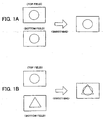
- the smoothing processing is appropriately executed as shown in FIG. 1A and unnecessary noise is eliminated when a top field image and a bottom field image match with each other.
- a field/frame determination process is executed in order to choose an appropriate combination of two field images subjected to the smoothing.
- one frame of image data js constituted by two fields. Those two field images are called “top field” and "bottom field”. Namely, the one frame image is constituted by the combination of one top field and one bottom field.
- the top field and the bottom field are also expressed as "ODD field” and "EVEN field”, or "first field” and "second field” in a usual image signal. However, it depends on a concrete format of the signal which one of the top field and the bottom field each of the ODD/EVEN or first/second fields corresponds to.
- the combination of the field images can be made, whichever may be chosen in two field images before and after, in time, the certain field image.
- the combinations of the field images subjected to the smoothing process can be the combination of (1) the n-th top field and the n-th bottom field, or (2) the n-th top field and the (n-1)-th bottom field.
- the smoothing process is executed by choosing one of those two combinations that has smaller difference in the image components. Therefore, the deficiency that the field images are smoothed by the combination having large difference of image components can be reduced.
- the image area of the field image is divided into a plurality of small areas (blocks), and the smoothing process is executed by the unit of the block.
- the smoothing is executed by the frame unit for the area in which the image components of two field images are less different, and the smoothing is executed by the field unit for the area in which the image components of two field images are more different.
- Executing the smoothing by the frame unit means that the smoothing process is executed between neighboring lines in the frame image.
- “Executing the smoothing by the field unit” means that the smoothing is executed between the neighboring lines in a field image (in a case of the frame image, between the lines jumping over one line). The above process is executed for each block.
- the smoothing is executed in the identical field in the small area (block) having large motion in the image, and the smoothing is executed between the neighboring fields in the small area (block) having small motion. Therefore, by considering whether the image components of the image data subjected to the smoothing changes largely or not, the smoothing can be executed by an appropriate method for each block.
- a smoothing processor of image data includes a data obtaining unit which obtains the image data including a plurality of unit image data arranged in time series, a determining unit which determines a difference between object unit image data which is subjected to processing and preceding unit image data which is immediately before the object unit image data and a difference between the object unit image data and subsequent unit image data which is immediately after the object unit image data, for a plurality of blocks constituting the unit image data, and a smoothing unit which executes smoothing by utilizing the object unit image data and one of the preceding unit image data and the subsequent unit image data having smaller difference, based on a determination result by the determining unit.
- the image data in which a plurality of object unit image data such as field images are arranged in a time series is supplied from an image source.
- the object unit image data is divided into blocks of a predetermined size.
- the difference between the object unit image data and the preceding unit image data which is immediately before the object unit image data, and the difference between the object unit image data and the subsequent unit image data which is immediately after the object unit image data are determined for each block.
- the difference of the obj ect unit image data is the difference of the image data components. Concretely, the difference may be the difference of pixel values constituting the image data.
- the object unit image data is smoothed with one of the preceding unit image data and the subsequent unit image data, whose difference is smaller. Therefore, the object unit image data is always smoothed with the object unit image data whose difference is the smallest, so an adverse effect caused by the smoothing can be prevented, and at the same time, effective noise elimination can be performed
- the determining unit may include a unit which determines whether or not the differences are equal to or larger than a predetermined value for each block and a unit which determines one of the preceding unit image data and the subsequent unit image data including less blocks whose difference is equal to or larger than the predetermined value, as the unit image data having smaller difference.
- the unit image data whose difference is larger can be determined by a simple comparative process.
- the smoothing unit may execute smoothing by utilizing the object unit image data and the unit image data having smaller difference for the block whose difference is smaller than the predetermined value, and execute smoothing by utilizing only the object unit image data for the block whose difference is equal to or larger than the predetermined value.
- smoothing is executed in a different method for each block by taking account of the differences in the smoothing process. Namely, since smoothing is executed by only for the object unit image data in the block determined that the difference is large, the deficiency (i.e., the object unit image data in which the difference is large is smoothed) can be prevented. As to the block determined that the difference is small, since smoothing is executed utilizing two object unit image data, noise can be effectively eliminated.
- a smoothing processing method of the image data including the identical process with the above-mentioned smoothing processor may be provided.
- the process by the above-mentioned smoothing processor may be realized in a form of a smoothing process program to be executed on a computer.
- FIG. 2 schematically shows a configuration of the compression coding system of the image data to which the prefilter according to the present invention is applied.
- an original image data D0 which is output from an image source 5 is supplied to a prefilter (smoothing filter) 10 of the present invention.
- the image source 5 may be a storage medium such as various sorts of optical discs and a hard disk
- the original image data D0 may be various sorts of image data including the 60-field image data, the 30-frame image data and the 2-3 pull-down image data, as described.
- the prefilter 10 executes appropriate smoothing to the original image data D0, and supplies the image data D1 after the smoothing process to an encoding unit 7.
- the encoding unit 7 may be an MPEG encoder, for example, which compression-codes the image data D1.
- DCT is executed to the image data D1
- encoded image data is output after quantizing and coding. It is noted that the image data which is compression-coded in that way is utilized by being recorded in a recording medium such as an optical disc and by being transmitted via a transmission channel.
- the prefilter 10 includes a memory 12, a frame/field determination unit 14, a smoothing unit 16, and an output buffer 18.
- the memory 12 has storage capacity which corresponds to four pieces of the field image.
- the memory 12 reads in the original image data D0 by the unit of the field image and temporarily stores the data.
- the frame/field determination unit 14 executes frame/field determination by utilizing the field images temporarily stored in the memory 12.
- the frame/field determination analyzes the components of the field images subjected to the determination and another field image. If the difference between those field images is smaller than a predetermined level, the frame/field determination determines that those two field images exist in a frame configuration. If the difference is larger than the predetermined level, the frame/field determination determines that those two field images exist in a field configuration. Though it is described in detail later, whether two field images are in the frame configuration or in the field configuration is determined for each block by dividing the image area into a plurality of blocks, and whether the whole field image is in the frame configuration or in the field configuration is determined based on the determination results of the plural blocks.
- the smoothing unit 16 executes the smoothing process of the frame image constituted by the field image subjected to processing and another field image, by the unit of each pixel.
- the smoothing is the process of averaging each pixel value with the pixel values in a predetermined neighboring range, and the process is generally executed by utilizing the smoothing filter.
- the smoothing unit 16 specifies the field image data subjected to smoothing. For each of the blocks of the field image data subjected to the smoothing, when it is determined by a frame/field determination process that the block is in the frame configuration, the smoothing is executed by the frame unit. When it is determined by the frame/field determination unit that the block is in the field configuration, the smoothing is executed by the field unit.
- the image data after the smoothing process which is temporarily stored in the output buffer 18, is output to the encoding unit 7.
- FIG. 3A shows an example of the image data constituting the original image data.
- the original image data is basically the image data alternately including a top field image and a bottom field image, and one frame image is constituted by combining one top field image and one bottom field image.
- the original image data includes TOP_01, TOP_02, TOP_03, ... , as the top field image, and includes BOTTOM_01, BOTTOM_02, BOTTOM_03 , ... , as the bottom field image.
- the original image data D0 is supplied to the memory 12 of the prefilter 10 in the order of TOP_01, BOTTOM_01, TOP_02 and BOTTOM_02.
- the memory 12 has four field memories. At the first timing, the memory 12 retains four field images: TOP_01, BOTTOM_01, TOP_02 and BOTTOM_02. At the next timing, the memory retains BOTTOM_01, TOP_02, BOTTOM_02, and TOP_03. In that way, four field images which are successive in time are always retained in the memory 12, while updating one field image.
- the frame image subjected to the smoothing by the prefilter 10 is TOP_2 as shown in FIG. 3A.
- four field images which are BOTTOM_01, TOP_02, BOTTOM_02 and TOP_03, are retained in the memory 12.
- TOP_02 which is the field image subjected to the processing can constitute the frame image if combined with the preceding field image BOTTOM_01 or the field image BOTTOM_02.
- the smoothing of the field image TOP_02 subjected to the processing can be executed by either the frame image constituted by the field images TOP_02 and BOTTOM_01 (referred to as "the first combination") or the frame image constituted by the field images TOP_02 and BOTTOM_02 (referred to as "the second combination"). Therefore, the frame/field determination unit 14 determines which combination is appropriate.
- the frame/field determination unit 14 divides each field image into 8x8-pixel blocks, and executes the frame/field determination for each block.
- FIG. 4 schematically shows one block of the frame image constituted by the field images TOP_02 and BOTTOM_01.
- a white square in FIG. 4 indicates one pixel of the top field image
- a hatched square indicates one pixel of the bottom field image.
- the pixel value e.g., a luminance value
- the pixel values "A" to "P” are the pixel values of the field image TOP_02
- the pixel values "a" to "h” are the pixel values of the field image BOTTOM_01.
- the frame/field determination unit 14 calculates a frame calculation value CR1 by an equation shown in FIG. 4 by utilizing the pixel values of the 1st and the 2nd lines of the frame image. Also, the frame/field determination unit 14 calculates a frame calculation value CR2 by utilizing the pixel values of the 2nd and 3rd lines of the frame image. By executing this process up to the combination of the 7th and 8th lines, the frame calculation values CR1 to CR7 are calculated, and a frame accumulation sum CR is calculated by summing the values. As understood by the equation in FIG. 4, the more similar the field images TOP_02 and BOTTOM_01 are, the smaller the value of the frame accumulation sum CR becomes. Conversely, the more different the field images TOP_02 and BOTTOM_01 are, the larger the value of the frame accumulation sum CR becomes.
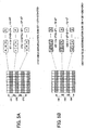
- the frame/field determination unit 14 calculates the field accumulation sum as shown in FIGS. 5A and 5B.
- top field calculation values CT1 to CT3 are calculated by the identical equation with the case of the frame calculation value, and the top field accumulation sum CT is obtained by summing the values.
- the more-similar-the pixel values of each line of the top field image TOP_02 are the smaller the top field accumulation sum CT becomes.
- the more different the pixel values of each line of the top field image TOP_02 are the larger the top field accumulation sum CT becomes.
- the field accumulation sum CT since the top field accumulation sum CT compares the pixel values within the identical field image, the field accumulation sum CT tends to be smaller than the frame accumulation sum.
- the frame/field determination unit 14 calculates a bottom field accumulation sum CB by the identical process as shown in FIG. 5B.
- the frame image subjected to the processing is constituted by the combination of the field images TOP_02 and BOTTOM_01 according to this example, the bottom field accumulation sum CB is calculated by utilizing each pixel value of the bottom field image BOTTOM_01.
- the frame/field determination unit 14 executes the frame/field determination for each block. Concretely, first of all, by the equations below, the 1st and 2nd determination values are calculated, and it is determined whether conditional equations (1) and (2) shown below are satisfied or not.
- 1 ⁇ st determination value CR - 2 ⁇ CT > 2000
- 2 ⁇ nd determination value CR - 2 ⁇ CB > 2000
- the frame/field determination unit 14 determines the block as a "field”. Unless both of the conditional equations (1) and (2) are satisfied, the block is determined as a "frame”.
- the frame/field determination unit 14 executes the frame/field determination by the unit of the block.
- the frame/field determination unit 14 calculates, as a field determination number fb1, the number of the blocks which are determined as "field”.
- the frame/field determination unit 14 executes the identical process to the other combination of the field images including the field image TOP_02 subjected to the processing, i.e. , the combination of the field images TOP_02 and BOTTOM_02, to calculate a field determination number fb2.
- the frame/field determination unit 14 determines which combination, i.e., the 1st or 2nd combination, should be utilized for the smoothing process, based on the field determination number.
- the frame/field determination unit 14 determines to constitute the frame image by one of 1st and 2nd combinations whose field determination number (i.e., a number of blocks determined as 'field') is smaller, i.e., by the combination having smaller differences between the field images, and to execute the smoothing.
- the smoothing process can be always executed for an appropriate combination. As a result, it can be prevented that the smoothing process is executed for the combination of the field images having a larger difference.
- FIG. 6 schematically shows the frame image subjected to the smoothing process.
- the frame image subjected to the smoothing process is the frame image constituted by the combination of the field images, which is determined as an object of the smoothing process by the above-mentioned frame/field determination process because the field determination number thereof is small.
- the field image subjected to the processing is the top field image TOP_02, and it is determined by the frame/field determination process that the smoothing process is executed to the frame image constituted by the combination of the field images TOP_02 and BOTTOM 02 as shown in FIG 3B.
- the frame image constituted by the combination of the field images TOP_02 and BOTTOM_02 becomes the object of the smoothing process.
- the frame image determined by the frame/field determination process either of the smoothing by the frame unit or the smoothing by the field unit is applied by the unit of the block.
- the block in this case is the block prescribed in the frame/field determination process, and is the 8x8 pixel block as shown in FIGS. 4, 5A and 5B.
- the frame/field determination process as to the frame image subjected to the processing, the frame/field determination has been completed for each block.
- FIG. 6 shows an example of a determination result thereof. It is noted that the determination result may be stored in the memory 12 in the prefilter 10.
- the block indicated by "FR" is the block determined as the "frame”
- the block indicated by "FI” is the block determined as the "field” by the frame/field determination process.
- the smoothing process by the frame unit is applied to the pixels in the block which is determined as the "frame"
- the smoothing process by the field unit is applied to the pixels in the block which is determined as the "field".
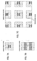
- FIG. 7A shows a constructive example of the smoothing filter by the frame unit
- FIG. 7B shows a constructive example of the smoothing filter by the field unit.
- the smoothing filter is generally the filter which uniformly varies the pixel values of the surrounding pixels which surround the pixel subjected to the processing as a center.
- a factor " a " of the smoothing filter is also called “smoothing factor”.
- the example shown in FIG. 7A is the smoothing filter of 3x3 pixel, smoothing filters, other than the 3 ⁇ 3 pixel filter, can be utilized.
- the smoothing process is executed for neighboring lines of the frame image subjected to the processing. Therefore, the smoothing filter by the frame unit executes filtering to 3 pixels in both vertical and horizontal directions of the frame image data.
- the smoothing process is executed independently for each field.
- the block determined as the "field” is smoothed by utilizing the pixel data of only the field image TOP_02.
- the smoothing filter by the field unit shown in FIG. 7B is, for ease of explanation, formed as the smoothing filter to be applied to the image data of a frame image state, i.e., a state in which two field images are combined, the hatched portions are not processed. So, substantially, the filter shown in FIG. 7B is the smoothing filter of 3x3 pixel by the field unit. It is noted that the smoothing filter shown in FIG. 7A may be utilized when the smoothing process is executed to the field image TOP_02 stored in the memory by a field image unit, in an actual process.
- each smoothing filter having a configuration shown in FIG. 7C is utilized according to the location of the pixel subjected to the processing. It is noted that the smoothing filters for the periphery of the image shown in FIG. 7C are also applied to the image data in a frame state like in FIG. 7A. In a case of smoothing by the field unit, the filters for the periphery of the image has a configuration having pixel portions (the hatched pixels) which are not subjected to the smoothing like in FIG. 7B.
- FIG. 8A shows a configurative example of the Sobel filter for the image data in the frame unit
- FIG. 8B shows a configurative example of the Sobel filter for the image data in the field unit.
- the Sobel filter is applied to each pixel of the frame or field image subjected to the processing. As a result, when an obtained value is larger than a predetermined threshold, the pixel is determined to be located on the border. When the obtained value is smaller than the predetermined threshold, the pixel is determined not to be located on the border.
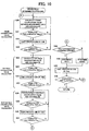
- FIG. 9 is a flow chart of a main routine of the prefiltering process
- FIG. 10 is a flow chart of the frame/field determination process
- FIG. 11 is a flow chart of the smoothing process.
- the prefilter 10 receives the original image data D0 from the image source 5 (step S1).
- the frame/field determination unit 14 executes the processing of top field image data. Namely, as shown in FIG. 3, the frame/field determination is executed to the frame image constituted by the combination of the top field image subjected to the processing (e.g., the top field image TOP_02) and the field image which is preceding to the top field image (e.g., the bottom field image BOTTOM_01), which is called "combination A" below (step S2). Thereby, the determination of frame or field is executed to the frame image of the combination A for each block, and the field determination number fb1 is obtained.
- the frame/field determination unit 14 executes the frame/field determination to the frame image constituted by the combination of the field image subj ected to the processing (e.g., the top field image TOP_02) and the field image corresponding to that image (e.g., the bottom field image BOTTOM_02), which is called "combination B" below (step S3).
- the determination of frame or field is executed to the frame image of the combination B for each block, and the field determination number fb2 is obtained.
- the frame/field determination unit 14 compares the field determination numbers fb1 of the combination A and fb2 of the combination B (step S4), and determines the frame image of the combination having the smaller field determination number as the object of the smoothing process. Then, the smoothing unit 16 executes the smoothing process by utilizing the corresponding frame image (step S5 or S6), and outputs the image data after the smoothing process to the encoding unit 7 via the output buffer 18 (step S7).
- the prefilter 10 executes the processing of the bottom field image.
- the prefilter 10 determines one of the frame image constituted by the combination (combination B) of the top field image TOP_02 and the bottom field image BOTTOM_02 and the frame image constituted by the combination (it is called "combination C" below) of the top field image TOP_03 and the bottom field image BOTTOM_02, for which frame image the smoothing process should be executed.
- the frame/field determination for the frame image of the combination B has already been completed in step S3
- only the frame/field determination for the frame image of the combination C is executed (step S8).
- the frame/field determination unit 14 determines one of the frame images of the combinations B and C, having the smaller field determination number, as the object of the smoothing process (step S9).
- the smoothing unit 16 executes the smoothing process for the frame image (step S10 or S11), and outputs the image data obtained as a result to the encoding unit 7 via the output buffer 18 (step S12).
- the prefilter 10 repeats the frame/field determination process and the smoothing process for the top field image and the bottom field image.
- the prefiltering process ends.
- the frame accumulation sum is calculated, as shown in FIG. 10.
- the frame calculation value CR1 is calculated by calculating squares of the differences of the pixel values corresponding to each other on the neighboring lines and by summing the squares for all the pixels in the horizontal direction of the block (steps S20 and S21).
- the frame calculation value CR2 is calculated by executing the identical process. If all the frame calculation values (CR1 to CR7 in the examples of FIG. 4) in one block are obtained (step S23; Yes) by repeating the process, the values are summed and the frame accumulation sum CR is calculated.
- the top field calculation value CT1, CT2, ... for each line are calculated for only the pixels corresponding to the top field of the block in the same way (steps S24 and S25), and the same calculation is executed for all lines in the vertical direction of the block (steps S26 and S27) to calculate the top field accumulation sum CT.
- the bottom field calculation value CB1, CB2, ... for each line is calculated for only the pixels corresponding to the bottom field of the block (steps S28 and S29), and the same calculation is executed for all lines in the vertical direction of the block (steps S30 and S31) to calculate the bottom field accumulation sum CB.
- the frame/field determination unit 14 determines whether the block satisfies the field determination conditions or not (step S32). Concretely, the frame/field determination unit 14 determines whether both of the above-mentioned conditional equations (1) and (2) are satisfied or not. If both of them are satisfied, the block is determined as the field (step S33). If at least one of the equations is not satisfied, the frame/field determination unit 14 determines the block as the frame (step S34). In this way, the frame/field determination for one block in the frame image subjected to the processing ends.
- the frame/field determination unit 14 shifts the block by one, and determines the block as the frame or the field by the identical process.
- the frame/field determination process ends.
- the smoothing process is executed in a state in which the frame images respectively subjected to the processing are specified in step S5, S6, S10 or S11 in FIG. 9.
- the smoothing unit 16 specifies one pixel in the frame image as the pixel subjected to the processing (hereinafter referred to as "process object pixel"), and determines whether the block to which the process object pixel belongs is the block determined as the frame or the field (step S41). Since the frame/field determination result of each block (see FIG. 6) is stored in the memory 12 in the prefilter 10 as described above, the smoothing unit 16 may refer to the result.
- the smoothing unit 16 chooses the smoothing filter by the frame unit as shown in FIG. 7A (step S42).
- the smoothing unit 16 chooses the smoothing filter by the field unit as shown in FIG. 7B (step S43).
- the smoothing unit 16 executes the above-mentioned Sobel filtering (step S44), and determines whether the process object pixel is located on the border or not (step S45).
- the smoothing unit 16 goes to step S47 without executing the smoothing process by the smoothing filter in order to prevent the problem that the letters and the outlines get out of shape by the smoothing process, as described above.
- the smoothing process is executed by applying the smoothing filter which is chosen in step S42 or S43 (step S46).
- the smoothing unit 16 specifies the next process object pixel (step S47), and determines whether the next process object exists or not (step S48). In this way, the smoothing unit 16 executes the smoothing process, in turn, for all the pixels of the frame image subjected to processing, and the smoothing process ends when the process is completed for all the pixels (step S48).
- the smoothing filter of the present invention is utilized as the prefilter which is applied as the preparation of a compression codingprocess by the MPEG
- the smoothing filter of the present invention can also be applied to a general smoothing process of image.
- the smoothing filter canbe installed in a general display to be used for noise elimination of a display image.
- calculation equations of the frame accumulation sum and the field accumulation sum in the frame/field determination and the conditional equations (1) and (2) in the embodiment are only examples. So, the frame/field determination can also be executed by other calculation equation and conditional equation.
- the smoothing processor includes a memory which obtains and stores the image data including a plurality of unit image data arranged in time series; a frame/field determining unit which determines a difference between object unit image data which is subjected to processing and preceding unit image data which is immediately before the object unit image data and a difference between the object unit image data and subsequent unit image data which is immediately after the object unit image data, for a plurality of blocks constituting the unit image data; and a smoothing unit which executes smoothing by utilizing the object unit image data and one of the preceding unit image data and the subsequent unit image data having a smaller difference, based on a determination result by the determining unit.
- the image data which includes a plurality of object unit image data arranged in time series, such as field images, is supplied from an image source.
- the object unit image data subjected to the smoothing process is divided into blocks of a predetermined size. Then, a difference between the object unit image data and preceding unit image data which is immediately before the object unit image data, and a difference between the object unit image data and subsequent unit image data which is immediately after the object unit image data are determined for a plurality of blocks, based on a pixel value.
- the object unit image data is smoothed with one of the preceding unit image data and the subsequent unit image data having a smaller difference.
Landscapes
- Engineering & Computer Science (AREA)
- Physics & Mathematics (AREA)
- General Physics & Mathematics (AREA)
- Theoretical Computer Science (AREA)
- Multimedia (AREA)
- Signal Processing (AREA)
- Computer Vision & Pattern Recognition (AREA)
- Compression Or Coding Systems Of Tv Signals (AREA)
- Image Processing (AREA)
- Apparatus For Radiation Diagnosis (AREA)
Claims (5)
- Processeur de lissage (10) de données d'image comprenant :une unité d'obtention de données (12) qui obtient les données d'image (D0) comprenant une pluralité de données d'image unitaires agencées en série chronologique ;une unité de détermination (14) qui détermine une différence entre les données d'image unitaires objets qui sont soumises à un traitement et les données d'image unitaires précédentes qui se trouvent juste avant les données d'image unitaires objets et une différence entre les données d'image unitaires objets et les données d'image unitaires suivantes qui se trouvent juste après les données d'image unitaires objets, pour une pluralité de blocs constituant les données d'image unitaires ; etune unité de lissage (16) qui exécute un lissage en utilisant les données d'image unitaires objets et les données d'image unitaires précédentes ou les données d'image unitaires suivantes ayant une plus petite différence, sur la base d'un résultat de détermination obtenu par l'unité de détermination.
- Processeur de lissage (10) des données d'image selon la revendication 1, dans lequel l'unité de détermination (14) comprend :une unité qui détermine, pour chacun des blocs, si une combinaison des données d'image unitaires objets et des données d'image unitaires précédentes et une combinaison des données d'image unitaires objets et des données d'image unitaires suivantes ont une configuration de champ ou une configuration de cadre, respectivement ; etune unité qui détermine les données d'image unitaires précédentes et les données d'image unitaires suivantes incluses dans la combinaison ayant moins de blocs déterminés pour avoir la configuration de champ, en tant que données d'image unitaires ayant une plus petite différence.
- Processeur de lissage (10) des données d'image selon la revendication 2, dans lequel l'unité de lissage (16) exécute un lissage du bloc déterminé pour avoir la configuration de trame en utilisant un filtre de lissage par une unité de cadre et exécute un lissage pour le bloc déterminé pour avoir la configuration de champ en utilisant un filtre de lissage par une unité de champ.
- Procédé de traitement de lissage de données d'image comprenant :une étape d'obtention de données qui obtient des données d'image (D0) comprenant une pluralité de données d'image unitaires agencées en série chronologique ;une étape de détermination qui détermine une différence entre les données d'image unitaires objets qui sont soumises à un traitement et les données d'image unitaires précédentes qui se trouvent juste avant les données d'image unitaires objets et une différence entre les données d'image unitaires objets et les données d'image unitaires suivantes qui se trouvent juste après les données d'image unitaires objets, pour une pluralité de blocs constituant les données d'image unitaires ; etune étape de lissage qui exécute un lissage en utilisant les données d'image unitaires objets et les données d'image unitaires précédentes ou les données d'image unitaires suivantes ayant une plus petite différence, sur la base d'un résultat de détermination obtenu par le processus de détermination.
- Programme informatique comprenant un moyen de codage adapté pour effectuer toutes les étapes du procédé de la revendication 4, lorsque ledit programme est exécuté sur un ordinateur.
Applications Claiming Priority (2)
| Application Number | Priority Date | Filing Date | Title |
|---|---|---|---|
| JP2002342599 | 2002-11-26 | ||
| JP2002342599A JP3715273B2 (ja) | 2002-11-26 | 2002-11-26 | 画像データの平滑化処理装置、平滑化処理方法及び平滑化処理プログラム |
Publications (3)
| Publication Number | Publication Date |
|---|---|
| EP1427215A2 EP1427215A2 (fr) | 2004-06-09 |
| EP1427215A3 EP1427215A3 (fr) | 2005-02-09 |
| EP1427215B1 true EP1427215B1 (fr) | 2007-02-21 |
Family
ID=32310641
Family Applications (1)
| Application Number | Title | Priority Date | Filing Date |
|---|---|---|---|
| EP20030257350 Expired - Lifetime EP1427215B1 (fr) | 2002-11-26 | 2003-11-21 | Procédé et appareil pour le lissage de données d'image |
Country Status (5)
| Country | Link |
|---|---|
| US (1) | US20040151397A1 (fr) |
| EP (1) | EP1427215B1 (fr) |
| JP (1) | JP3715273B2 (fr) |
| CN (1) | CN1503562A (fr) |
| DE (1) | DE60311946T2 (fr) |
Families Citing this family (4)
| Publication number | Priority date | Publication date | Assignee | Title |
|---|---|---|---|---|
| KR100555866B1 (ko) * | 2004-06-08 | 2006-03-03 | 삼성전자주식회사 | 패턴 적응형 필터링에 의한 영상신호의 평활화 장치 및 그평활화 방법 |
| JP2008109247A (ja) * | 2006-10-24 | 2008-05-08 | Matsushita Electric Ind Co Ltd | ビデオ・ノイズをフィルタリングする方法、装置、集積回路およびエンコーダ |
| EP2109310B8 (fr) * | 2008-04-11 | 2018-05-16 | Tektronix International Sales GmbH | Procédé de quantification d'un mouvement inter-champs dans une image vidéo |
| JP6573375B2 (ja) * | 2015-06-24 | 2019-09-11 | キヤノン株式会社 | 画像処理装置、画像処理装置の制御方法およびプログラム |
Family Cites Families (11)
| Publication number | Priority date | Publication date | Assignee | Title |
|---|---|---|---|---|
| JPS592227B2 (ja) * | 1978-08-21 | 1984-01-17 | 株式会社日立製作所 | 雑音除去方式 |
| US5237413A (en) * | 1991-11-19 | 1993-08-17 | Scientific-Atlanta, Inc. | Motion filter for digital television system |
| TW293227B (fr) * | 1994-11-24 | 1996-12-11 | Victor Company Of Japan | |
| JPH09252468A (ja) * | 1996-03-15 | 1997-09-22 | Minolta Co Ltd | 画像圧縮装置 |
| EP1119979B1 (fr) * | 1998-09-29 | 2013-01-23 | General Instrument Corporation | Technique et dispositif permettant de detecter des modifications sceniques et d'adapter le type de codage d'image dans un codeur de television haute definition |
| IL138671A (en) * | 1999-01-27 | 2005-12-18 | Koninkl Philips Electronics Nv | Record carrier, playback device and method of recording information |
| JP4288805B2 (ja) * | 1999-12-28 | 2009-07-01 | ソニー株式会社 | 映像信号再生装置 |
| KR100611094B1 (ko) * | 2000-06-15 | 2006-08-09 | 주식회사 케이티 | 통계적 모델에 기반한 워터마크 삽입/검출 장치 및 그 방법 |
| ATE401647T1 (de) * | 2001-05-02 | 2008-08-15 | Pioneer Corp | Informationsaufzeichnungsmedium und informationsaufzeichnungsgerät |
| JP3713574B2 (ja) * | 2001-05-29 | 2005-11-09 | コニカミノルタビジネステクノロジーズ株式会社 | 画像処理装置、画像処理方法およびプログラム |
| EP1293971B1 (fr) * | 2001-09-14 | 2008-07-16 | Pioneer Corporation | Support d'enregistrement d'informations, appareil de reproduction d'informations et appareil d'enregistrement d'informations |
-
2002
- 2002-11-26 JP JP2002342599A patent/JP3715273B2/ja not_active Expired - Fee Related
-
2003
- 2003-11-21 DE DE2003611946 patent/DE60311946T2/de not_active Expired - Fee Related
- 2003-11-21 EP EP20030257350 patent/EP1427215B1/fr not_active Expired - Lifetime
- 2003-11-26 CN CNA2003101179862A patent/CN1503562A/zh active Pending
- 2003-11-26 US US10/721,771 patent/US20040151397A1/en not_active Abandoned
Also Published As
| Publication number | Publication date |
|---|---|
| EP1427215A2 (fr) | 2004-06-09 |
| JP3715273B2 (ja) | 2005-11-09 |
| CN1503562A (zh) | 2004-06-09 |
| JP2004179886A (ja) | 2004-06-24 |
| US20040151397A1 (en) | 2004-08-05 |
| DE60311946D1 (de) | 2007-04-05 |
| DE60311946T2 (de) | 2007-12-06 |
| EP1427215A3 (fr) | 2005-02-09 |
Similar Documents
| Publication | Publication Date | Title |
|---|---|---|
| US6188799B1 (en) | Method and apparatus for removing noise in still and moving pictures | |
| US6226050B1 (en) | Signal adaptive filtering method for reducing ringing noise and signal adaptive filter | |
| US6259823B1 (en) | Signal adaptive filtering method and signal adaptive filter for reducing blocking effect and ringing noise | |
| JP3095140B2 (ja) | ブロック化効果の低減のための一次元信号適応フィルター及びフィルタリング方法 | |
| US5974197A (en) | Loop filter and loop filtering method | |
| KR101312260B1 (ko) | 에지 영역을 효과적으로 압축하고 복원하는 방법 및 장치 | |
| US7430337B2 (en) | System and method for removing ringing artifacts | |
| CN103141094A (zh) | 自适应环路滤波方法和装置 | |
| CN1170318A (zh) | 减少运动补偿图象的成组效应和振铃噪声的环形滤波方法 | |
| GB2316826A (en) | Moving object detection in a coded moving picture signal | |
| JP4995344B2 (ja) | フィルタリング装置 | |
| US7043092B1 (en) | Video decoding device and method using a deblocking filtering step | |
| JPH06292173A (ja) | 映像信号符号化復号化方法 | |
| CN117135349A (zh) | 图像编码方法、图像解码方法、装置以及存储介质 | |
| US5787207A (en) | Method and apparatus for minimizing blockiness in reconstructed images | |
| EP1758401A2 (fr) | Prétraitement ayant pour but l'utilisation d'une seule interpolation avec compensation de mouvement pour de différents standards de codage vidéo | |
| EP1848219B1 (fr) | Dispositif d'élimination de bruit de bloc | |
| US8891609B2 (en) | System and method for measuring blockiness level in compressed digital video | |
| EP1427215B1 (fr) | Procédé et appareil pour le lissage de données d'image | |
| KR20010080611A (ko) | 필터링 장치 및 방법 | |
| EP1018841A1 (fr) | Systeme de codage d'images | |
| JPH11187400A (ja) | 歪除去方法および歪除去フィルタ | |
| EP1032218B1 (fr) | Dispositif et procede de codage et de decodage | |
| JP3176270B2 (ja) | 画像復号化処理方法 | |
| EP1570678B1 (fr) | Procede de mesure d'artefacts de blocage |
Legal Events
| Date | Code | Title | Description |
|---|---|---|---|
| PUAI | Public reference made under article 153(3) epc to a published international application that has entered the european phase |
Free format text: ORIGINAL CODE: 0009012 |
|
| AK | Designated contracting states |
Kind code of ref document: A2 Designated state(s): AT BE BG CH CY CZ DE DK EE ES FI FR GB GR HU IE IT LI LU MC NL PT RO SE SI SK TR |
|
| AX | Request for extension of the european patent |
Extension state: AL LT LV MK |
|
| PUAL | Search report despatched |
Free format text: ORIGINAL CODE: 0009013 |
|
| AK | Designated contracting states |
Kind code of ref document: A3 Designated state(s): AT BE BG CH CY CZ DE DK EE ES FI FR GB GR HU IE IT LI LU MC NL PT RO SE SI SK TR |
|
| AX | Request for extension of the european patent |
Extension state: AL LT LV MK |
|
| 17P | Request for examination filed |
Effective date: 20050728 |
|
| AKX | Designation fees paid |
Designated state(s): DE FR GB |
|
| GRAP | Despatch of communication of intention to grant a patent |
Free format text: ORIGINAL CODE: EPIDOSNIGR1 |
|
| GRAS | Grant fee paid |
Free format text: ORIGINAL CODE: EPIDOSNIGR3 |
|
| GRAA | (expected) grant |
Free format text: ORIGINAL CODE: 0009210 |
|
| AK | Designated contracting states |
Kind code of ref document: B1 Designated state(s): DE FR GB |
|
| REG | Reference to a national code |
Ref country code: GB Ref legal event code: FG4D |
|
| REF | Corresponds to: |
Ref document number: 60311946 Country of ref document: DE Date of ref document: 20070405 Kind code of ref document: P |
|
| ET | Fr: translation filed | ||
| REG | Reference to a national code |
Ref country code: GB Ref legal event code: 746 Effective date: 20071007 |
|
| PLBE | No opposition filed within time limit |
Free format text: ORIGINAL CODE: 0009261 |
|
| STAA | Information on the status of an ep patent application or granted ep patent |
Free format text: STATUS: NO OPPOSITION FILED WITHIN TIME LIMIT |
|
| 26N | No opposition filed |
Effective date: 20071122 |
|
| PGFP | Annual fee paid to national office [announced via postgrant information from national office to epo] |
Ref country code: DE Payment date: 20071115 Year of fee payment: 5 |
|
| PGFP | Annual fee paid to national office [announced via postgrant information from national office to epo] |
Ref country code: GB Payment date: 20071121 Year of fee payment: 5 Ref country code: FR Payment date: 20071108 Year of fee payment: 5 |
|
| GBPC | Gb: european patent ceased through non-payment of renewal fee |
Effective date: 20081121 |
|
| REG | Reference to a national code |
Ref country code: FR Ref legal event code: ST Effective date: 20090731 |
|
| PG25 | Lapsed in a contracting state [announced via postgrant information from national office to epo] |
Ref country code: DE Free format text: LAPSE BECAUSE OF NON-PAYMENT OF DUE FEES Effective date: 20090603 |
|
| PG25 | Lapsed in a contracting state [announced via postgrant information from national office to epo] |
Ref country code: GB Free format text: LAPSE BECAUSE OF NON-PAYMENT OF DUE FEES Effective date: 20081121 |
|
| PG25 | Lapsed in a contracting state [announced via postgrant information from national office to epo] |
Ref country code: FR Free format text: LAPSE BECAUSE OF NON-PAYMENT OF DUE FEES Effective date: 20081130 |