EP1428593A1 - Méthode et dispositif pour la séparation des fils d'un faisceau de fils - Google Patents
Méthode et dispositif pour la séparation des fils d'un faisceau de fils Download PDFInfo
- Publication number
- EP1428593A1 EP1428593A1 EP02406082A EP02406082A EP1428593A1 EP 1428593 A1 EP1428593 A1 EP 1428593A1 EP 02406082 A EP02406082 A EP 02406082A EP 02406082 A EP02406082 A EP 02406082A EP 1428593 A1 EP1428593 A1 EP 1428593A1
- Authority
- EP
- European Patent Office
- Prior art keywords
- wires
- wire
- feed direction
- feed
- lifting element
- Prior art date
- Legal status (The legal status is an assumption and is not a legal conclusion. Google has not performed a legal analysis and makes no representation as to the accuracy of the status listed.)
- Withdrawn
Links
Images
Classifications
-
- B—PERFORMING OPERATIONS; TRANSPORTING
- B65—CONVEYING; PACKING; STORING; HANDLING THIN OR FILAMENTARY MATERIAL
- B65G—TRANSPORT OR STORAGE DEVICES, e.g. CONVEYORS FOR LOADING OR TIPPING, SHOP CONVEYOR SYSTEMS OR PNEUMATIC TUBE CONVEYORS
- B65G47/00—Article or material-handling devices associated with conveyors; Methods employing such devices
- B65G47/02—Devices for feeding articles or materials to conveyors
- B65G47/04—Devices for feeding articles or materials to conveyors for feeding articles
- B65G47/12—Devices for feeding articles or materials to conveyors for feeding articles from disorderly-arranged article piles or from loose assemblages of articles
- B65G47/14—Devices for feeding articles or materials to conveyors for feeding articles from disorderly-arranged article piles or from loose assemblages of articles arranging or orientating the articles by mechanical or pneumatic means during feeding
- B65G47/1407—Devices for feeding articles or materials to conveyors for feeding articles from disorderly-arranged article piles or from loose assemblages of articles arranging or orientating the articles by mechanical or pneumatic means during feeding the articles being fed from a container, e.g. a bowl
-
- B—PERFORMING OPERATIONS; TRANSPORTING
- B21—MECHANICAL METAL-WORKING WITHOUT ESSENTIALLY REMOVING MATERIAL; PUNCHING METAL
- B21F—WORKING OR PROCESSING OF METAL WIRE
- B21F23/00—Feeding wire in wire-working machines or apparatus
- B21F23/005—Feeding discrete lengths of wire or rod
Definitions
- the invention relates to a method for separating wires of a wire bundle or Similar long, thin, bundled objects, with the wire bundle on an in Feed direction inclined feed plane is given so that the wires are in effect to move the force of gravity onto a control element with a control gap, which is a has a diameter of the wires adapted width and to accommodate the isolated Wires in the form of a single-layer wire layer is formed.
- CH 691 669 shows such a method, with the wire bundle several processing elements arranged side by side is processed before it reached the control gap.
- the processing elements have a feed level parallel scraper edge and a scraper edge directed against the wire bundle.
- the coating edge is passed over a single-layer wire layer that has just been created, lifted off and returned to the starting point. That means it will be one circular motion, similar to the manual separation of the wires through an operator.
- the scraper edge pushes all those wires to the wire bundle back, which protrude beyond the single-layer wire level.
- a swiveling scraper thumb detects at the entrance of the Control gap all wires lying over the lowest wire layer and pushes them to Wire bundle back.
- the wiping thumb performs a linear movement.
- the object of the invention is a technical field mentioned at the beginning to create the associated method, which is suitable for separating wires and improves the feeding of the wires and their parallel alignment.
- the procedure should be able to be implemented mechanically with as little technical effort as possible.
- the solution to the problem is defined by the features of claim 1.
- According to the Invention is a lifting element through the feed plane upwards, against the Direction of feed against the moving wires.
- the upward movement of the lifting element counteracts gravity. This leads to to ensure that the wires, which act under the influence of gravity on the guide element move there, be loosened up. At the same time, some of the wires, especially those which are still crossed or wedged into each other, again against the feed direction pushed back so that the number of wires conveyed to the guide element per Unit of time is reduced. As a result, the separation of the wires is additional and is supported before the management body. Finally, the loosening leads of the wires and pushing back part of the wires for better feeding to the Management body by preventing interlocking wires from accessing the Block control gap. A blockage that forms is in fact caused by the lifting element dissolved early.
- the feed level can be through a solid plate, through a guide grid or through Guide bars or other means are formed.
- the feeding direction is understood to be that geometric direction which the Direction of transport of the wires when feeding along the inclined feed plane to the Management body with control gap corresponds. It is essentially parallel to the fall line the inclined feed level.
- the method according to the invention is not restricted to the separation of wires, rather, other long, thin bundled objects can also be processed.
- the lifting element preferably acts with one relative to the lifting element arranged expansion space together.
- This expansion space takes up wires which are pushed up by the lifting element and promotes their parallel Orientation.
- the wires can pass through the lifting element and reach the governing body under the influence of gravity.
- the size of the expansion space is advantageously adjustable. If the height and / or the The depth of the expansion space can be changed, the process for wire separation Dimensions of the wires, in particular their diameter, in a simple manner be adjusted. In this case, the width of the control gap is preferably also available the wire diameter adjustable.
- the wire bundle is advantageously stowed in a storage space, the storage space in Feed direction is formed behind a wire retention element.
- Lifting element in front of a storage space can be the number of wires on the Lifting element arrive, be dosed. Even if a large wire bundle is attached to the Given the feed plane, only a certain number of wires pass through it Wire retention element and reaches the lifting element. At the same time, the pressure reduced to the separation zone at the lifting element. Both causes the parallel alignment of the wires and further transport to the guide member improved become.
- another method step can also be provided which reduces the number of wires fed to the separation zone, e.g. B. mechanical means which divide the wire bundle and the individual parts in the Transport separation zone.
- the expansion space is preferably separated from the storage space and is in Feed direction arranged in front of the storage space.
- the wires to be separated are thus first stowed in the storage space so that the pressure on the separation zone is reduced.
- the lifting element and the one arranged opposite act in the separation zone Expansion space together so that the wires fed into the separation zone aligned in parallel and finally moved to the management body.
- the expansion space is advantageously designed as a recess in the wire retention element.
- the wire retention element also serves to form a storage space behind the element and to separate storage space and expansion space.
- a recess which is delimited by walls on a substantial part of its inner surface furthermore the advantage that the wires, which are to be aligned in parallel, are optimal and that they cannot get caught on edges or in recesses.
- a separate wire retention element and a separate one Guide member may be spaced one behind the other, the space between the Forms expansion space.
- the guide means for Includes wires from the expansion space for. B. an opening to Expansion space, which tapers in the feed direction.
- the lifting element is preferably star-shaped and rotates counter to the feed direction.
- a star-shaped lifting element has one or more arms, which rotate of the element through the feed level up and there on the moving wires.
- the feed level has recesses, e.g. B. Slits through which the arms go up, through the feed level can.
- Lifting element has a certain symmetry, e.g. B. by two opposite arms or has a larger number of arms that are even on the circumference of the element are arranged. This eliminates the imbalance of the element and thus the load on the Bearing of the element kept low.
- the shape of the arms is advantageously chosen so that they pass through the Apply the feed level gradually to the wires. This is e.g. B. achieved in that the outer, essentially tangential limitation of an arm as it passes is inclined against the feed plane by the feed plane.
- the arms can be humped or serrations formed on the circumference of the element or as a radial arm his.
- Different arms of a lifting element can also be designed differently, z. B. by arms along the circumference of the star-shaped lifting element, which especially lead to a lifting of the wires, alternate with arms, which above all to one Push the wires back.
- the lifting element can also be designed differently, e.g. B. as an eccentric disc or Lifting plate, which is periodically, randomly or sensor-controlled through the feed level is moved up and back through.
- the drive of such a lifting plate can e.g. B. via a pneumatically or hydraulically operated piston, a cam or a connecting rod.
- the isolated parallel wires can be connected to the guide element Drive plate are supplied, which the individual wires in a predetermined Further promotes distance.
- the inclination of the feed plane is chosen so that the wires are under the effect of the Move gravity towards the guide member at a desired speed.
- the width of the feed plane corresponds to the wire length.
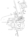
- Figure 1 shows a cross section of an inventive device for separating Wires, such as those used in a lattice welding machine to separate the Cross wires can be used.
- the device has one against the feed direction inclined feed level 1. This is on the top of an inclined machine base 2 arranged.
- the feed plane 1 advantageously has ribs running in the feed direction, to minimize the friction between the wires and the feed plane.
- Ribs can e.g. B. are formed by wires that are welded onto a metal sheet.
- a wire retainer 3 is arranged, which in the Is essentially designed as a vertical flat plate, the main surface of which is parallel to Feed direction is.
- the boundary of the plate has on the feed level 1 facing outer side has a rounded shape so that the opening between the Feed level 1 and the wire retainer 3 are continuously narrowed in the feed direction. Behind the wire retainer 3 a storage space 4 is thereby formed.
- the wire retainer 3 has an essentially rectangular one on its underside Recess 5 with rounded edges so that the opening between the Feed level 1 and the wire retainer 3 is expanded in sections and a Expansion space 6 is formed.
- the wire retainer 3 forms at its inner end facing the feed plane 1 Guide member 7, the boundary of which is flat on the underside, so that a control gap 8 in the form of a channel with a constant cross section between the wire retainer 3 and the feed plane 1 is formed.
- the entrance of the control gap 8 widens in Direction of expansion space 6.
- the wire retainer 3 is attached to a holding device 9 so that it is vertical can be moved. This allows the width to be increased or decreased of the control gap 8, so that the device has different diameters individual wires can be adjusted. At the same time, the vertical Expansion of the expansion space 6 changed.
- the feed level 1 has a slot-shaped opening, the slot being oriented in the feed direction.
- Arms 10, 11 reach through this slot of a lifting element 12 through the feed plane 1 upwards.
- the lifting element 12 is formed by a disk 13 rotatably mounted in the machine base 2 whose outer boundary the two arms 10, 11 are arranged.
- the cross section of the Arms 10, 11 are substantially trapezoidal, with the outer boundary sloping runs, so that when the disk 13 rotates, the part of the arms 10, 11 which over the feed plane protrudes, increases continuously in the feed direction.
- the disk 13 is driven by a belt 14 which is moved by a motor 15 can.
- the belt 14 is guided by a pulley 16 so that it by two Openings in the underside of the machine base 2 are guided around the disk 13 can.
- the feed plane 1 has another slot-shaped one Recess in the feed direction, in which a rotatably mounted, essentially circular drive plate (or combing disc) 17 engages the main plane is also in the feed direction.
- the driving plate 17 has on its outer edge periodic recesses.
- the drive plate 17 is furthermore connected a conveyor belt 18.
- the method according to the invention is carried out using the device shown in FIG follows.
- a bundle of wires from a large number of prepared, long ones thin wires are placed on the feed level 1.
- Move by gravity the wires of the bundle tends towards the wire retainer 3
- the outer limit gradually tapering in the direction of the feed plane becomes the majority the wires are retained in the storage space 4.
- Only the wires of the bottom one, on the Layers 1 overlying layers can open the opening between the wire retainer Pass 3 and the feed level 1 and continue to slide or roll in the feed direction.
- the wires aligned in parallel in the expansion space 6 fall due to gravity again on the feed level 1.
- the speed of the motor 15 and thus the rotating disc 13 of the lifting element 12, that is the frequency with which one of the Arms 10, 11 passes through the feed plane 1 can be adjusted or regulated in such a way that the moment the parallel wires are back on the Feed level 1 arrives, no lifting process is currently taking place.
- the wires can be so continue to move freely in the feed direction and pass through as a single-layer wire layer the control gap 8 of the management organ 7. This is just high enough for a single layer Layer of wire with little play has space and crossed wires are retained. Its height is z. B. 1.1 to 1.4 times the wire diameter. In any case the height must be less than twice the wire diameter.
- the drive plate 17 rotates in the feed direction and detects with each of them Recesses a single wire, which has passed the control gap 8.
- the now isolated wires are further conveyed and driven by the drive plate 17 for further transportation z. B. placed on the conveyor belt 18 at a constant distance.
- the Wire retainer 3 moved away from the feed plane 1, so that on the one hand the Control gap 8 widened and on the other hand the expansion space is enlarged.
- the method and the device in the form shown are particularly for wires suitable, the length of which is approximately 800 times as large as its diameter.
- the device according to the invention can also be of other wire lengths and diameters be adjusted. Another way to adjust is when the slope of the expansion space can be adjusted.
- the number of devices for wire separation can also be different can be selected which are parallel along the width of the feed plane (i.e. the length of the Wires) are arranged. In this case, the separation can still be improved, if the lifting elements of the devices are driven in different phases become. With shorter (or thicker) wires, however, it can be optimal, the individual To drive devices in phase. In both cases, the phase differences by a common one that extends over the entire width of the device Drive shaft to be fixed.
- the speed of rotation of the lifting element and thus the frequency of the The lifting movement does not have to be constant. Rather, it can also be done by sensors are controlled, the z. B. the number of wires in the expansion or storage space or others Measure parameters.
- the speed or frequency of the lifting element is in this Case continuously adapted to the current situation so that the parallel arrangement of the wires and the slipping of new wires are optimally promoted.
- the Phase shift between different, arranged in the width of the feed plane Devices can be flexibly controlled in a similar manner by sensors.
- the device can be designed so that the height of the control gap is independent is adjustable from the size of the expansion space, e.g. B. by the control gap by a element formed by the wire retainer.
- the size of the expansion space can also be changed by adjusting the width of the expansion space become.
- the invention provides a method and a method Device are created, which are suitable for separating wires and improve the feeding of the wires and their parallel alignment and which ones Particularly suitable for the separation of cross wires in lattice welding machines are.
- the principle on which the invention is based also allows isolation other wire-like objects.
Landscapes
- Engineering & Computer Science (AREA)
- Mechanical Engineering (AREA)
- Feeding Of Articles To Conveyors (AREA)
Priority Applications (2)
| Application Number | Priority Date | Filing Date | Title |
|---|---|---|---|
| EP02406082A EP1428593A1 (fr) | 2002-12-09 | 2002-12-09 | Méthode et dispositif pour la séparation des fils d'un faisceau de fils |
| EP03405883A EP1428595A1 (fr) | 2002-12-09 | 2003-12-09 | Méthode et dispositif pour la séparation des fils d'un trousseau de fils |
Applications Claiming Priority (1)
| Application Number | Priority Date | Filing Date | Title |
|---|---|---|---|
| EP02406082A EP1428593A1 (fr) | 2002-12-09 | 2002-12-09 | Méthode et dispositif pour la séparation des fils d'un faisceau de fils |
Publications (1)
| Publication Number | Publication Date |
|---|---|
| EP1428593A1 true EP1428593A1 (fr) | 2004-06-16 |
Family
ID=32319730
Family Applications (1)
| Application Number | Title | Priority Date | Filing Date |
|---|---|---|---|
| EP02406082A Withdrawn EP1428593A1 (fr) | 2002-12-09 | 2002-12-09 | Méthode et dispositif pour la séparation des fils d'un faisceau de fils |
Country Status (1)
| Country | Link |
|---|---|
| EP (1) | EP1428593A1 (fr) |
Cited By (2)
| Publication number | Priority date | Publication date | Assignee | Title |
|---|---|---|---|---|
| CN106586475A (zh) * | 2017-01-09 | 2017-04-26 | 深圳星精丰科技有限公司 | 一种螺丝排列及输送设备 |
| CN106697866A (zh) * | 2017-01-09 | 2017-05-24 | 深圳星精丰科技有限公司 | 一种螺丝排列及输送设备 |
Citations (4)
| Publication number | Priority date | Publication date | Assignee | Title |
|---|---|---|---|---|
| DE738828C (de) * | 1937-07-04 | 1943-10-27 | Karl Lange | Verfahren zur Drahtstabzufuehrung bei Schweisselektrodenumhuellungseinrichtungen und Vorrichtung zur Durchfuehrung des Verfahrens |
| DE1111907B (de) * | 1955-11-03 | 1961-07-27 | Boehler & Co Ag Geb | Vorrichtung zum Zufuehren gleichartiger Werkstuecke, insbesondere Schweissstaebe |
| CH442150A (de) * | 1964-11-23 | 1967-08-15 | Eickhoff Geb | Vorrichtung an Vorratsbehälter für stabförmige Teile, zum Vereinzeln der Teile, die aus dem Vorratsbehälter abgezogen werden |
| WO2001038020A1 (fr) * | 1999-11-19 | 2001-05-31 | Evg Entwicklungs- Und Verwertungs-Gesellschaft M. B.H. | Procede et dispositif pour la manipulation de fils metalliques |
-
2002
- 2002-12-09 EP EP02406082A patent/EP1428593A1/fr not_active Withdrawn
Patent Citations (4)
| Publication number | Priority date | Publication date | Assignee | Title |
|---|---|---|---|---|
| DE738828C (de) * | 1937-07-04 | 1943-10-27 | Karl Lange | Verfahren zur Drahtstabzufuehrung bei Schweisselektrodenumhuellungseinrichtungen und Vorrichtung zur Durchfuehrung des Verfahrens |
| DE1111907B (de) * | 1955-11-03 | 1961-07-27 | Boehler & Co Ag Geb | Vorrichtung zum Zufuehren gleichartiger Werkstuecke, insbesondere Schweissstaebe |
| CH442150A (de) * | 1964-11-23 | 1967-08-15 | Eickhoff Geb | Vorrichtung an Vorratsbehälter für stabförmige Teile, zum Vereinzeln der Teile, die aus dem Vorratsbehälter abgezogen werden |
| WO2001038020A1 (fr) * | 1999-11-19 | 2001-05-31 | Evg Entwicklungs- Und Verwertungs-Gesellschaft M. B.H. | Procede et dispositif pour la manipulation de fils metalliques |
Cited By (2)
| Publication number | Priority date | Publication date | Assignee | Title |
|---|---|---|---|---|
| CN106586475A (zh) * | 2017-01-09 | 2017-04-26 | 深圳星精丰科技有限公司 | 一种螺丝排列及输送设备 |
| CN106697866A (zh) * | 2017-01-09 | 2017-05-24 | 深圳星精丰科技有限公司 | 一种螺丝排列及输送设备 |
Similar Documents
| Publication | Publication Date | Title |
|---|---|---|
| DE3244292A1 (de) | Muenzen-uebergabevorrichtung | |
| DE10201182A1 (de) | Positioniersystem | |
| DD287460A5 (de) | Verfahren und vorrichtung zum aufeinanderfolgenden foerdern von flachen gegenstaenden | |
| DE2809642C2 (de) | Verfahren und Vorrichtung zur Herstellung von Waffelblöcken | |
| DE102011013919A1 (de) | Schneidmaschine | |
| EP1428758B1 (fr) | Dispositif pour trier et transporter des matériaux en vrac | |
| EP3628610A1 (fr) | Dispositif d'alignement et de séparation des objets disponibles en tant que produit en vrac | |
| EP0379481B1 (fr) | Dispositif et procede pour separer des produits en vrac de volume relativement faible | |
| DE2602154A1 (de) | Verbesserte vorrichtung zum ordnen von durcheinander anfallenden gegenstaenden, und um dieselben einzeln aufeinanderfolgend zu einer einwickelmaschine zu beschicken, insbesondere fuer pralinen und dergleichen | |
| DE60028163T2 (de) | Vorrichtung zum Zuführen von Zigarren | |
| EP1428593A1 (fr) | Méthode et dispositif pour la séparation des fils d'un faisceau de fils | |
| DE10151971C2 (de) | Vorrichten zum Vereinzeln von Baumstämmen | |
| EP1428595A1 (fr) | Méthode et dispositif pour la séparation des fils d'un trousseau de fils | |
| DE4406089C2 (de) | Vorrichtung zum Abfüllen von Tabletten oder dergleichen in Tablettenröhrchen | |
| DE112005002865B4 (de) | Blockwendeanordnung | |
| DE2140371A1 (de) | Sortiervorrichtung | |
| DE916277C (de) | Zufuehrungsvorrichtung fuer Schrauben und andere Gegenstaende | |
| DE4421116C1 (de) | Verfahren und Vorrichtung zum Stapeln und Abtransportieren von in Scheiben geschnittenem Stranggut | |
| DE2547899A1 (de) | Vorrichtung zum aufloesen oder zusammenstellen insbesondere von flaschenkastenschichten oder -bloecken | |
| DE1937389C (de) | · Automatische Futterungsanlage | |
| DE1199187B (de) | Einrichtung zum gleichsinnigen Ausrichten von Parkettstaeben | |
| EP1148014A2 (fr) | Dispositif de formation de piles | |
| DE1657169A1 (de) | Flaschenabgabevorrichtung | |
| DE2008250A1 (de) | Vorrichtung zur Aufnahme und Abgabe der aus einem Walzwerk austretenden Metallstangen | |
| DE43743C (de) | Neuerungan Abschneideapparaten für Ziegelpressen |
Legal Events
| Date | Code | Title | Description |
|---|---|---|---|
| PUAI | Public reference made under article 153(3) epc to a published international application that has entered the european phase |
Free format text: ORIGINAL CODE: 0009012 |
|
| AK | Designated contracting states |
Kind code of ref document: A1 Designated state(s): AT BE BG CH CY CZ DE DK EE ES FI FR GB GR IE IT LI LU MC NL PT SE SI SK TR |
|
| AX | Request for extension of the european patent |
Extension state: AL LT LV MK RO |
|
| AKX | Designation fees paid | ||
| REG | Reference to a national code |
Ref country code: DE Ref legal event code: 8566 |
|
| STAA | Information on the status of an ep patent application or granted ep patent |
Free format text: STATUS: THE APPLICATION IS DEEMED TO BE WITHDRAWN |
|
| 18D | Application deemed to be withdrawn |
Effective date: 20041217 |