EP1428622A1 - Schlauch mit optischer Vorrichtung - Google Patents
Schlauch mit optischer Vorrichtung Download PDFInfo
- Publication number
- EP1428622A1 EP1428622A1 EP20030028554 EP03028554A EP1428622A1 EP 1428622 A1 EP1428622 A1 EP 1428622A1 EP 20030028554 EP20030028554 EP 20030028554 EP 03028554 A EP03028554 A EP 03028554A EP 1428622 A1 EP1428622 A1 EP 1428622A1
- Authority
- EP
- European Patent Office
- Prior art keywords
- hose
- optical device
- housing
- work tool
- blower
- Prior art date
- Legal status (The legal status is an assumption and is not a legal conclusion. Google has not performed a legal analysis and makes no representation as to the accuracy of the status listed.)
- Withdrawn
Links
Images



Classifications
-
- B—PERFORMING OPERATIONS; TRANSPORTING
- B23—MACHINE TOOLS; METAL-WORKING NOT OTHERWISE PROVIDED FOR
- B23Q—DETAILS, COMPONENTS, OR ACCESSORIES FOR MACHINE TOOLS, e.g. ARRANGEMENTS FOR COPYING OR CONTROLLING; MACHINE TOOLS IN GENERAL CHARACTERISED BY THE CONSTRUCTION OF PARTICULAR DETAILS OR COMPONENTS; COMBINATIONS OR ASSOCIATIONS OF METAL-WORKING MACHINES, NOT DIRECTED TO A PARTICULAR RESULT
- B23Q17/00—Arrangements for observing, indicating or measuring on machine tools
- B23Q17/24—Arrangements for observing, indicating or measuring on machine tools using optics or electromagnetic waves
- B23Q17/2404—Arrangements for improving direct observation of the working space, e.g. using mirrors or lamps
-
- B—PERFORMING OPERATIONS; TRANSPORTING
- B23—MACHINE TOOLS; METAL-WORKING NOT OTHERWISE PROVIDED FOR
- B23Q—DETAILS, COMPONENTS, OR ACCESSORIES FOR MACHINE TOOLS, e.g. ARRANGEMENTS FOR COPYING OR CONTROLLING; MACHINE TOOLS IN GENERAL CHARACTERISED BY THE CONSTRUCTION OF PARTICULAR DETAILS OR COMPONENTS; COMBINATIONS OR ASSOCIATIONS OF METAL-WORKING MACHINES, NOT DIRECTED TO A PARTICULAR RESULT
- B23Q11/00—Accessories fitted to machine tools for keeping tools or parts of the machine in good working condition or for cooling work; Safety devices specially combined with or arranged in, or specially adapted for use in connection with, machine tools
- B23Q11/0042—Devices for removing chips
- B23Q11/0046—Devices for removing chips by sucking
-
- B—PERFORMING OPERATIONS; TRANSPORTING
- B23—MACHINE TOOLS; METAL-WORKING NOT OTHERWISE PROVIDED FOR
- B23Q—DETAILS, COMPONENTS, OR ACCESSORIES FOR MACHINE TOOLS, e.g. ARRANGEMENTS FOR COPYING OR CONTROLLING; MACHINE TOOLS IN GENERAL CHARACTERISED BY THE CONSTRUCTION OF PARTICULAR DETAILS OR COMPONENTS; COMBINATIONS OR ASSOCIATIONS OF METAL-WORKING MACHINES, NOT DIRECTED TO A PARTICULAR RESULT
- B23Q11/00—Accessories fitted to machine tools for keeping tools or parts of the machine in good working condition or for cooling work; Safety devices specially combined with or arranged in, or specially adapted for use in connection with, machine tools
- B23Q11/0042—Devices for removing chips
- B23Q11/005—Devices for removing chips by blowing
-
- B—PERFORMING OPERATIONS; TRANSPORTING
- B23—MACHINE TOOLS; METAL-WORKING NOT OTHERWISE PROVIDED FOR
- B23D—PLANING; SLOTTING; SHEARING; BROACHING; SAWING; FILING; SCRAPING; LIKE OPERATIONS FOR WORKING METAL BY REMOVING MATERIAL, NOT OTHERWISE PROVIDED FOR
- B23D59/00—Accessories specially designed for sawing machines or sawing devices
- B23D59/006—Accessories specially designed for sawing machines or sawing devices for removing or collecting chips
- B23D59/0062—Accessories specially designed for sawing machines or sawing devices for removing or collecting chips by blowing
-
- Y—GENERAL TAGGING OF NEW TECHNOLOGICAL DEVELOPMENTS; GENERAL TAGGING OF CROSS-SECTIONAL TECHNOLOGIES SPANNING OVER SEVERAL SECTIONS OF THE IPC; TECHNICAL SUBJECTS COVERED BY FORMER USPC CROSS-REFERENCE ART COLLECTIONS [XRACs] AND DIGESTS
- Y10—TECHNICAL SUBJECTS COVERED BY FORMER USPC
- Y10T—TECHNICAL SUBJECTS COVERED BY FORMER US CLASSIFICATION
- Y10T83/00—Cutting
- Y10T83/04—Processes
- Y10T83/0448—With subsequent handling [i.e., of product]
- Y10T83/0453—By fluid application
-
- Y—GENERAL TAGGING OF NEW TECHNOLOGICAL DEVELOPMENTS; GENERAL TAGGING OF CROSS-SECTIONAL TECHNOLOGIES SPANNING OVER SEVERAL SECTIONS OF THE IPC; TECHNICAL SUBJECTS COVERED BY FORMER USPC CROSS-REFERENCE ART COLLECTIONS [XRACs] AND DIGESTS
- Y10—TECHNICAL SUBJECTS COVERED BY FORMER USPC
- Y10T—TECHNICAL SUBJECTS COVERED BY FORMER US CLASSIFICATION
- Y10T83/00—Cutting
- Y10T83/828—With illuminating or viewing means for work
Definitions
- the present invention relates to a hose for removing debris from a work area and in particular to a hose with an optical device for illuminating a work area and removing debris.
- a work tool that includes a housing.
- a blower provides one of a positive or negative pressure and is connected to the housing.
- a hose has a first end connected with the blower and an opposite second end.
- An optical device for illuminating a work area is positioned at least partially within the second end of the housing.
- Another aspect of the invention includes a second housing attached to the first housing.
- the second housing includes a blower that provides a negative pressure.
- a flexible hose has a first end connected with the blower and an opposite second end.
- An optical device for illuminating a work area is positioned at least partially within the second end of the housing.
- Another aspect of the invention includes a method for illuminating and cleaning a work area associated with a work tool.
- the work tool includes a housing, a hose, and an optical device located at least partially within the hose.
- the method includes actuating the work tool and directing the hose about the work area.
- the hose provides one of a positive or negative pressure.
- the tool of the present invention will be described as a table saw.
- table saw does not limit the scope of the present invention.
- FIG. 1 is a perspective view of an embodiment of the hose with an optical device according to the present invention and incorporated into a table saw.
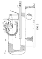
- FIG. 2 is a side plan view of the embodiment of FIG. 1, with a portion of the housing removed.
- FIG. 3 is a front plan view of the optical device positioned within the hose.
- FIG. 4 is a side plan view of an alternate embodiment showing the blower separate from the table saw, with a portion of the second housing removed.
- FIG. 1 an optical device 2 at least partially located within a hose 4 is shown.
- the hose 4 is connected with a table saw 6.
- the tooling associated with the table saw 6 is conventional.
- the description provided herein contemplates the hose 4 being used in conjunction with a table saw 6, those skilled in the art will readily recognize that the hose may be used with a variety of tools that may generate debris or shavings, such as metal or wood chips or dust, for example. Examples of other tools include, but are not limited to, miter saws, milling machines, various types of drills and drill presses, or any other type of tool where the use of the tool may generate debris in the general work area of the tool.
- the hose 4 is a flexible tube made from PVC, although other suitable materials may be used. Other suitable materials include but are not limited to plastics, rubbers, and lower-strength flexible metals. It is preferable that the hose is flexible so that it may be manipulated about the area of a work table 8 (FIG. 1) or other type of work area. To provide further flexibility, the hose 4 may also include a variety of segments 10, thus allowing the hose to be easily manipulated at sharp angles. Although a flexible hose is contemplated, the hose may be made from more rigid materials.
- the table saw 6 includes a blower 12.
- a first end 14 of the hose 4 is connected to an outlet 15 of the blower 12.
- the blower 12 is housed within a housing 18 and is electrically connected with the table saw.
- a switch 19 may be provided so that the blower may be actuated separately from the table saw.
- the blower 12 provides a positive pressure so that a gas such as air is expelled from a second end 16 of the hose 4.
- the blower is conventional, and the amount of pressure provided depends upon manufacturing preferences, and in some embodiments may be variable. Thus, the hose clears or "blows" the debris away from the work table.
- the second end 16 of the hose is opposite the first end 14 and includes an optical device 2.
- the optical device 2 provides illumination as the hose 4 is manipulated about the work table 8.
- the optical device 2 preferably is an LED, although other illuminating devices may also be used. Other suitable devices include but are not limited to incandescent, halogen, fluorescent, or tungsten illuminating devices.
- the optical device 2 is connected to an electrical device that can be a battery 20 housed within the housing 18, and may be actuated through the use of a switch 22. Note that in other embodiments, the optical device may be electrically connected with the table saw so that it is actuated along with, rather than separately from, the table saw.
- the optical device 2 is positioned within the hose 4 so that it protrudes at least partially from the second end 16 of the hose. As shown in FIG. 3, the optical device 2 should be sized so that its circumference 24 at its widest part is less than the inner circumference 26 of the second end 16 of the hose. Sizing the optical device 2 in this way thus allows the positive pressure to be freely expelled from the second end 16 of the hose 4.
- a blower 112 may provide a negative, or vacuum, pressure so that the debris is vacuumed up by the hose 104.
- the first end 114 of the hose also provides an egress for collected debris.
- the blower may be within a second housing 150 so that the debris may be collected.
- the blower may be electrically connected with the table saw in the manner described above. The interface between the optical device 2 and the hose 4 will be as described above.
- a user To clean a work area associated with a tool, a user simply grasps the hose and manipulates it about portions of the work area that the user desires to clean. Depending on whether a positive or negative pressure is expelled from the hose 4, debris will either be blown or vacuumed from the work area. If the hose 4 is actuated via a switch, the switch will need to be actuated. As noted above, the work area may also be illuminated via the optical device 2. To illuminate the work area, the switch associated with the optical device is actuated. A user then simply directs the hose 4 about the work area to the portions of the work area the user desires to illuminate.
- an optical device 2 positioned at least partially within a hose 4 and its method of use have been described herein.
- the optical device 2 provides the benefit of illuminating the work table so that the work table may be thoroughly cleared.
- the optical device 2 provides the additional benefit of illuminating the area where the tool works upon a workpiece.
- the optical device 2 may be positioned so that it provides optimum illumination to a user working with the tool.
Landscapes
- Engineering & Computer Science (AREA)
- Mechanical Engineering (AREA)
- Physics & Mathematics (AREA)
- Optics & Photonics (AREA)
- Sawing (AREA)
- Auxiliary Devices For Machine Tools (AREA)
Applications Claiming Priority (2)
| Application Number | Priority Date | Filing Date | Title |
|---|---|---|---|
| US316798 | 1989-02-28 | ||
| US10/316,798 US20040112191A1 (en) | 2002-12-11 | 2002-12-11 | Hose with optical device |
Publications (1)
| Publication Number | Publication Date |
|---|---|
| EP1428622A1 true EP1428622A1 (de) | 2004-06-16 |
Family
ID=32325924
Family Applications (1)
| Application Number | Title | Priority Date | Filing Date |
|---|---|---|---|
| EP20030028554 Withdrawn EP1428622A1 (de) | 2002-12-11 | 2003-12-11 | Schlauch mit optischer Vorrichtung |
Country Status (6)
| Country | Link |
|---|---|
| US (1) | US20040112191A1 (de) |
| EP (1) | EP1428622A1 (de) |
| JP (1) | JP2004188593A (de) |
| CN (1) | CN1520967A (de) |
| AU (1) | AU2003266795A1 (de) |
| CA (1) | CA2452971A1 (de) |
Families Citing this family (15)
| Publication number | Priority date | Publication date | Assignee | Title |
|---|---|---|---|---|
| US7509900B2 (en) * | 2001-02-20 | 2009-03-31 | Young Ronald E | Scroll saw with dust collector |
| US6912788B2 (en) * | 2003-03-03 | 2005-07-05 | Credo Technology Corporation | Blade storage compartment for power tool vacuum port |
| GB2399537A (en) * | 2003-03-13 | 2004-09-22 | Black & Decker Inc | Method and apparatus for removing dust from a workpiece |
| US20050099801A1 (en) * | 2003-10-10 | 2005-05-12 | Ross Zhang | Sawing direction positioning system for a jigsaw |
| EP1790432B1 (de) * | 2005-11-28 | 2014-01-08 | Black & Decker, Inc. | Kraftwerkzeug wie Stichsäge ausgerüstet mit Mitteln für das Entfernen der Späne vom Werstück |
| US8067916B2 (en) * | 2008-01-23 | 2011-11-29 | Su Hak Auh | Power cutting tool with synchronized dust control device |
| JP4804512B2 (ja) * | 2008-07-22 | 2011-11-02 | 茂雄 上田 | 照明付きノズル |
| US9931704B2 (en) * | 2013-05-06 | 2018-04-03 | Nanjing Chevron Industry Co., Ltd. | Line-of-sight blower for a power tool |
| US9821389B2 (en) * | 2013-08-28 | 2017-11-21 | Shave Away Europe, Inc. | Dust capturing device for reciprocating saws |
| DE102014011133A1 (de) * | 2014-05-27 | 2015-12-03 | Liebherr-Verzahntechnik Gmbh | Schleuderstation und Druckluftreinigungsanordnung |
| DE102014226025A1 (de) | 2014-12-16 | 2016-06-16 | Robert Bosch Gmbh | Optische Anzeigevorrichtungseinheit zur Verwendung in einer externen Anwendungseinheit |
| CN110000687A (zh) * | 2019-04-24 | 2019-07-12 | 卢雪薇 | 一种金属板材抛光用加工平台 |
| CN111300528A (zh) * | 2019-12-12 | 2020-06-19 | 徐州东控仪器有限公司 | 一种智能设备加工生产用切割装置 |
| CN113103376A (zh) * | 2020-06-04 | 2021-07-13 | 戚利明 | 一种木材切割用锯末收集装置 |
| CN117020279B (zh) * | 2023-10-08 | 2023-12-19 | 江苏科源阀门制造有限公司 | 一种手柄蝶阀生产加工用铣槽装置 |
Citations (4)
| Publication number | Priority date | Publication date | Assignee | Title |
|---|---|---|---|---|
| US2517882A (en) * | 1947-08-11 | 1950-08-08 | Johnson Moses | Illuminated hand held motor tool |
| DE3324615A1 (de) * | 1982-11-27 | 1984-05-30 | Robert Bosch Gmbh, 7000 Stuttgart | Vorrichtung zum auffangen von bohrklein |
| US4875398A (en) * | 1988-01-15 | 1989-10-24 | Atlantic Richfield Company | Retractable dust control hood and guard for rotary table saw |
| US6012373A (en) | 1995-09-19 | 2000-01-11 | Delta International Machinery Corp. | Composite material C-arm scroll saw |
Family Cites Families (26)
| Publication number | Priority date | Publication date | Assignee | Title |
|---|---|---|---|---|
| US2852051A (en) * | 1957-01-03 | 1958-09-16 | Clarence T Bickner | Power operated hand manipulated router |
| US3267974A (en) * | 1964-07-16 | 1966-08-23 | Black & Decker Mfg Co | Saw dust blower for portable power-driven saw |
| US3510228A (en) * | 1967-04-24 | 1970-05-05 | O C White Co The | Fume dispersing work lamp |
| US3785271A (en) * | 1972-02-07 | 1974-01-15 | Ventrola Mfg Co | New low profile ventilator apparatus means |
| US3890126A (en) * | 1974-06-03 | 1975-06-17 | Raymond Lee Organization Inc | Smoke lamp drawing device |
| US3882598A (en) * | 1974-06-17 | 1975-05-13 | Johns Manville | Dust control cutting assembly for cutting sheet material |
| US4109144A (en) * | 1975-08-11 | 1978-08-22 | Sherwood Refractories Inc. | Dust collection and illumination system |
| US4195403A (en) * | 1979-05-09 | 1980-04-01 | Gruber Clarence R | Sawdust removal device |
| US4759349A (en) * | 1986-02-24 | 1988-07-26 | Vitalmetrics, Inc. | Surgical instrument having a heat sink for irrigation, aspiration, and illumination |
| US4868369A (en) * | 1987-09-17 | 1989-09-19 | Chen Shu Mu | Soldering iron stand having an automatically actuated noxious fume removal arrangement |
| DE3734013C1 (de) * | 1987-10-08 | 1989-03-23 | Metabowerke Kg | Handwerkzeugmaschine mit hin- und herbewegbarem,spangebendem Werkzeug |
| US5529580A (en) * | 1987-10-30 | 1996-06-25 | Olympus Optical Co., Ltd. | Surgical resecting tool |
| US4887193A (en) * | 1987-12-15 | 1989-12-12 | Dieckmann Ralf E | Mounting apparatus for a lamp or similar device |
| US5236423A (en) * | 1988-12-13 | 1993-08-17 | Endomed Corporation | Facilitating endoscopy |
| US5199174A (en) * | 1992-04-13 | 1993-04-06 | Wild Jeffrey C | Sawdust removal apparatus |
| US5539985A (en) * | 1994-11-21 | 1996-07-30 | Wershe; Richard | Blower attachment for a circular saw |
| CA2198036C (en) * | 1996-02-20 | 2000-12-05 | Charles S. Taylor | Access platform for internal mammary dissection |
| US5983443A (en) * | 1997-12-30 | 1999-11-16 | Philips Electronics North America Corporation | Accessory with built-in light for vacuum cleaner |
| DE19815598B4 (de) * | 1998-04-07 | 2007-01-18 | Stm Medizintechnik Starnberg Gmbh | Flexibles Zugangsrohr mit Stülpschlauchsystem |
| US6470778B1 (en) * | 1998-05-20 | 2002-10-29 | Black & Decker Inc. | Dust collector for a power tool |
| USD437442S1 (en) * | 1999-06-03 | 2001-02-06 | James W. Lucas | Vented work light |
| US6447443B1 (en) * | 2001-01-13 | 2002-09-10 | Medtronic, Inc. | Method for organ positioning and stabilization |
| JP2001300867A (ja) * | 2000-04-21 | 2001-10-30 | Makita Corp | 電動工具用アダプタ |
| US20020109986A1 (en) * | 2001-02-12 | 2002-08-15 | Siegel Martin J. | Compliant flexible connector |
| US6692431B2 (en) * | 2001-09-07 | 2004-02-17 | Smith & Nephew, Inc. | Endoscopic system with a solid-state light source |
| US6912788B2 (en) * | 2003-03-03 | 2005-07-05 | Credo Technology Corporation | Blade storage compartment for power tool vacuum port |
-
2002
- 2002-12-11 US US10/316,798 patent/US20040112191A1/en not_active Abandoned
-
2003
- 2003-12-09 AU AU2003266795A patent/AU2003266795A1/en not_active Abandoned
- 2003-12-11 CN CNA2003101097877A patent/CN1520967A/zh active Pending
- 2003-12-11 JP JP2003413312A patent/JP2004188593A/ja active Pending
- 2003-12-11 EP EP20030028554 patent/EP1428622A1/de not_active Withdrawn
- 2003-12-11 CA CA 2452971 patent/CA2452971A1/en not_active Abandoned
Patent Citations (4)
| Publication number | Priority date | Publication date | Assignee | Title |
|---|---|---|---|---|
| US2517882A (en) * | 1947-08-11 | 1950-08-08 | Johnson Moses | Illuminated hand held motor tool |
| DE3324615A1 (de) * | 1982-11-27 | 1984-05-30 | Robert Bosch Gmbh, 7000 Stuttgart | Vorrichtung zum auffangen von bohrklein |
| US4875398A (en) * | 1988-01-15 | 1989-10-24 | Atlantic Richfield Company | Retractable dust control hood and guard for rotary table saw |
| US6012373A (en) | 1995-09-19 | 2000-01-11 | Delta International Machinery Corp. | Composite material C-arm scroll saw |
Also Published As
| Publication number | Publication date |
|---|---|
| US20040112191A1 (en) | 2004-06-17 |
| JP2004188593A (ja) | 2004-07-08 |
| CN1520967A (zh) | 2004-08-18 |
| AU2003266795A1 (en) | 2004-07-01 |
| CA2452971A1 (en) | 2004-06-11 |
Similar Documents
| Publication | Publication Date | Title |
|---|---|---|
| US20040112191A1 (en) | Hose with optical device | |
| JP3448110B2 (ja) | 吸引機構を有するドリル/チゼル装置 | |
| US6988435B2 (en) | Sawdust collection assembly for a compound miter saw | |
| US4361957A (en) | Pneumatic hand tool with vacuum debris removal | |
| CN100571988C (zh) | 用于加工机的抽吸装置 | |
| CN101130242B (zh) | 吸尘系统 | |
| US5440809A (en) | Dust collector for hand-held power tool | |
| US20090183800A1 (en) | Dust shroud for gas powered circular saws | |
| US20090007441A1 (en) | Variable dust chute for circular saws | |
| CN100436016C (zh) | 从工件上除去碎屑的方法和装置 | |
| CN100553842C (zh) | 电动手持式切割工具 | |
| JPH02502981A (ja) | ひき回し鋸 | |
| SE0203154D0 (sv) | Handverktygsmaskin med dammbehållare | |
| US11478865B2 (en) | Cutting device with integrated and interruptible auxiliary power supply | |
| US20060185173A1 (en) | Method and apparatus for removing dust from a workpiece | |
| US6173499B1 (en) | Vent cover for an electric saw | |
| US20220134502A1 (en) | Dust collection and debris removal device | |
| JP2003011101A (ja) | 手持ち式電動工具 | |
| CN1974093B (zh) | 具有用于从工件去除碎屑的装置的动力工具 | |
| US20070034064A1 (en) | Dust-collecting unit and electric tool having the same | |
| US20040060719A1 (en) | Universal suction attachment for pneumatic power tools | |
| FR2551686A1 (fr) | Outil travaillant par enlevement de copeaux | |
| JP3001478U (ja) | 穴あけ装置 | |
| JPH07237193A (ja) | 穴あけ装置 | |
| US7399004B2 (en) | Universal attachment for capturing and utilizing exhaust gas from pneumatic power tools |
Legal Events
| Date | Code | Title | Description |
|---|---|---|---|
| PUAI | Public reference made under article 153(3) epc to a published international application that has entered the european phase |
Free format text: ORIGINAL CODE: 0009012 |
|
| AK | Designated contracting states |
Kind code of ref document: A1 Designated state(s): AT BE BG CH CY CZ DE DK EE ES FI FR GB GR HU IE IT LI LU MC NL PT RO SE SI SK TR |
|
| AX | Request for extension of the european patent |
Extension state: AL LT LV MK |
|
| 17P | Request for examination filed |
Effective date: 20041007 |
|
| AKX | Designation fees paid |
Designated state(s): AT BE BG CH CY CZ DE DK EE ES FI FR GB GR HU IE IT LI LU MC NL PT RO SE SI SK TR |
|
| GRAP | Despatch of communication of intention to grant a patent |
Free format text: ORIGINAL CODE: EPIDOSNIGR1 |
|
| STAA | Information on the status of an ep patent application or granted ep patent |
Free format text: STATUS: THE APPLICATION IS DEEMED TO BE WITHDRAWN |
|
| 18D | Application deemed to be withdrawn |
Effective date: 20060620 |