EP1429043A2 - Méthode et dispositif pour assemblage de palier - Google Patents
Méthode et dispositif pour assemblage de palier Download PDFInfo
- Publication number
- EP1429043A2 EP1429043A2 EP03257743A EP03257743A EP1429043A2 EP 1429043 A2 EP1429043 A2 EP 1429043A2 EP 03257743 A EP03257743 A EP 03257743A EP 03257743 A EP03257743 A EP 03257743A EP 1429043 A2 EP1429043 A2 EP 1429043A2
- Authority
- EP
- European Patent Office
- Prior art keywords
- spring
- bearing
- damper
- groove
- assembly
- Prior art date
- Legal status (The legal status is an assumption and is not a legal conclusion. Google has not performed a legal analysis and makes no representation as to the accuracy of the status listed.)
- Withdrawn
Links
Images

Classifications
-
- F—MECHANICAL ENGINEERING; LIGHTING; HEATING; WEAPONS; BLASTING
- F16—ENGINEERING ELEMENTS AND UNITS; GENERAL MEASURES FOR PRODUCING AND MAINTAINING EFFECTIVE FUNCTIONING OF MACHINES OR INSTALLATIONS; THERMAL INSULATION IN GENERAL
- F16C—SHAFTS; FLEXIBLE SHAFTS; ELEMENTS OR CRANKSHAFT MECHANISMS; ROTARY BODIES OTHER THAN GEARING ELEMENTS; BEARINGS
- F16C33/00—Parts of bearings; Special methods for making bearings or parts thereof
- F16C33/30—Parts of ball or roller bearings
- F16C33/58—Raceways; Race rings
- F16C33/581—Raceways; Race rings integral with other parts, e.g. with housings or machine elements such as shafts or gear wheels
-
- F—MECHANICAL ENGINEERING; LIGHTING; HEATING; WEAPONS; BLASTING
- F01—MACHINES OR ENGINES IN GENERAL; ENGINE PLANTS IN GENERAL; STEAM ENGINES
- F01D—NON-POSITIVE DISPLACEMENT MACHINES OR ENGINES, e.g. STEAM TURBINES
- F01D25/00—Component parts, details, or accessories, not provided for in, or of interest apart from, other groups
- F01D25/16—Arrangement of bearings; Supporting or mounting bearings in casings
- F01D25/162—Bearing supports
- F01D25/164—Flexible supports; Vibration damping means associated with the bearing
-
- F—MECHANICAL ENGINEERING; LIGHTING; HEATING; WEAPONS; BLASTING
- F16—ENGINEERING ELEMENTS AND UNITS; GENERAL MEASURES FOR PRODUCING AND MAINTAINING EFFECTIVE FUNCTIONING OF MACHINES OR INSTALLATIONS; THERMAL INSULATION IN GENERAL
- F16C—SHAFTS; FLEXIBLE SHAFTS; ELEMENTS OR CRANKSHAFT MECHANISMS; ROTARY BODIES OTHER THAN GEARING ELEMENTS; BEARINGS
- F16C27/00—Elastic or yielding bearings or bearing supports, for exclusively rotary movement
- F16C27/04—Ball or roller bearings, e.g. with resilient rolling bodies
- F16C27/045—Ball or roller bearings, e.g. with resilient rolling bodies with a fluid film, e.g. squeeze film damping
-
- F—MECHANICAL ENGINEERING; LIGHTING; HEATING; WEAPONS; BLASTING
- F16—ENGINEERING ELEMENTS AND UNITS; GENERAL MEASURES FOR PRODUCING AND MAINTAINING EFFECTIVE FUNCTIONING OF MACHINES OR INSTALLATIONS; THERMAL INSULATION IN GENERAL
- F16C—SHAFTS; FLEXIBLE SHAFTS; ELEMENTS OR CRANKSHAFT MECHANISMS; ROTARY BODIES OTHER THAN GEARING ELEMENTS; BEARINGS
- F16C19/00—Bearings with rolling contact, for exclusively rotary movement
- F16C19/22—Bearings with rolling contact, for exclusively rotary movement with bearing rollers essentially of the same size in one or more circular rows, e.g. needle bearings
- F16C19/24—Bearings with rolling contact, for exclusively rotary movement with bearing rollers essentially of the same size in one or more circular rows, e.g. needle bearings for radial load mainly
- F16C19/26—Bearings with rolling contact, for exclusively rotary movement with bearing rollers essentially of the same size in one or more circular rows, e.g. needle bearings for radial load mainly with a single row of rollers
-
- F—MECHANICAL ENGINEERING; LIGHTING; HEATING; WEAPONS; BLASTING
- F16—ENGINEERING ELEMENTS AND UNITS; GENERAL MEASURES FOR PRODUCING AND MAINTAINING EFFECTIVE FUNCTIONING OF MACHINES OR INSTALLATIONS; THERMAL INSULATION IN GENERAL
- F16C—SHAFTS; FLEXIBLE SHAFTS; ELEMENTS OR CRANKSHAFT MECHANISMS; ROTARY BODIES OTHER THAN GEARING ELEMENTS; BEARINGS
- F16C2360/00—Engines or pumps
- F16C2360/23—Gas turbine engines
Definitions
- This application relates generally to gas turbine engine rotor assemblies and, more particularly, to bearing assemblies for gas turbine engine rotor assemblies.
- Gas turbine engines typically includes a fan rotor assembly, a compressor, and a turbine.
- the fan rotor assembly includes a fan including an array of fan blades extending radially outward from a rotor shaft.
- the rotor shaft transfers power and rotary motion from the turbine to the compressor and the fan, and is supported longitudinally with a plurality of bearing assemblies.
- Bearing assemblies support the rotor shaft and typically include rolling elements located within an inner race and an outer race.
- At least some known damper bearing assemblies include a plurality of springs attached between the bearing outer race and a mounting flange.
- the springs support the bearing and act as an antirotation device that substantially prevents the bearing outer race from rotating with respect to a bearing support.
- at least some known bearing supports include a catcher device that is coupled to the bearing assembly to substantially limit aft movement of the bearing outer race with respect to the bearing support if high dynamic loading is induced into the bearing assembly.
- At least some known damper bearing assemblies are positioned within sumps, and space limitations within the sump do not enable a catcher device to be coupled to the bearing assembly without expensive design modifications. Furthermore, because such bearing assemblies are positioned in the sumps, such assemblies may be exposed to high operating temperatures and soakback conditions, and thus may require costly seal assemblies to facilitate preventing sump oil leakage.
- a method for assembling a gas turbine engine rotor assembly includes a rotor shaft and a bearing assembly that includes an annular damper bearing and an annular spring.
- the method comprises forming at least one groove that is defined within and extends partially circumferentially around at least one of the annular damper and the annular spring, supporting the rotor shaft with the annular spring, and coupling the annular damper bearing to the annular spring using the at least one groove such that the spring extends circumferentially between the damper bearing and the rotor shaft.
- a bearing assembly for a gas turbine engine rotor in another aspect of the invention, includes an annular spring and an annular damper bearing.
- the annular spring is configured to support the gas turbine engine rotor.
- the annular damper bearing is concentrically aligned with the annular spring, and is radially outward from said annular spring, such that the damper bearing supports the spring.
- At least one of the damper bearing and the spring includes at least one groove defined therein.
- At least one of the damper bearing and the spring includes a retainer extending therefrom. The at least one groove is sized to receive the retainer therein for coupling the damper bearing to the spring.
- a rotor assembly in yet a further aspect, includes a rotor shaft and a bearing assembly.
- the bearing assembly supports the rotor shaft, and includes an annular damper bearing and an annular spring.
- the damper bearing extends circumferentially around the spring such that the spring is between the damper bearing and the rotor shaft.
- At least one of the damper bearing and the spring includes at least one groove defined therein for slidably coupling the damper bearing to the spring.
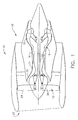
- FIG. 1 is a schematic illustration of a gas turbine engine 10 including a fan assembly 12, a high pressure compressor 14, and a combustor 16.
- Engine 10 also includes a high pressure turbine 18, a low pressure turbine 20, and a booster 22.
- Fan assembly 12 includes an array of fan blades 24 extending radially outward from a rotor disc 26.
- Engine 10 has an intake side 28 and an exhaust side 30.
- Airflow (not shown in Figure 1) from combustor 16 drives turbines 18 and 20, and turbine 20 drives fan assembly 12.
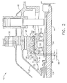
- FIG 2 is a cross-sectional view of an exemplary embodiment of a rotor assembly 40 that may be used with a gas turbine engine, such as engine 10 shown in Figure 1.
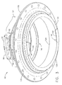
- Figure 3 is a partial perspective view of an exemplary unassembled bearing assembly 42 that may be used with rotor assembly 40
- Figure 4 is a partial perspective view of bearing assembly 42 shown in an assembled configuration.
- the gas turbine engine is an LMX 7000 available from General Electric Company, Cincinnati, Ohio.
- Rotor and bearing assembly 40 includes a rotor shaft 44 which supports an array of fan blades 24 (shown in Figure 1) that extend radially outward from rotor disc 26.
- Rotor shaft 44 is rotatably secured to a structural support frame 46 with a plurality of bearing assemblies 42 that support rotor shaft 44.
- bearing assembly 42 is a damper bearing assembly
- support frame 46 is a sump housing.
- Bearing assembly 42 includes a paired race 50 and a rolling element 52, positioned within a sump 53 radially bounded by shaft 44 and housing 46.
- Paired race 50 includes an outer race 54 and an inner race 56 that is radially inward from outer race 54.
- Rolling element 52 is located between inner race 56 and outer race 54.
- Outer race 54 is formed integrally with a plurality of spring fingers58, such that a face 60 of outer race 54 is positioned in rollable contact with rolling element 52.
- Spring fingers 58 are spaced circumferentially around shaft 44. In an alternative embodiment, fingers 58 are coupled to outer race 54.
- Outer race 54 includes a pair of annular grooves 70 and 72 that are defined in a radially outer surface 74 of outer race 54. More specifically, grooves 70 and 72 extend radially inwardly from spring finger member outer surface 74 and are positioned respectively upstream and downstream from an upstream side 76 and a downstream side 78 of outer race 54.
- Outer race 54 also includes at least one retainer groove 80 that extends radially inwardly from outer surface 74, such that retainer groove 80 is aligned substantially perpendicularly to an axis of rotation of rotor assembly 40.
- groove 80 is formed by machining.
- Retainer groove 80 is arcuate and extends only partially circumferentially around spring finger member 58. More specifically, retainer groove 80 is positioned between groove 70 and an upstream edge 84 of outer race 54, such that retainer groove 70 is a distance 86 from member edge 84.
- outer race 54 includes a pair of identical grooves 80 that are oppositely positioned and are offset from each other by approximately 180°. In an alternative embodiment, race 54 includes more than two grooves 80.
- Each groove 80 has a width 88, and an arcuate length 90 that is measured between a stop edge 92 and an entrance slot 94.
- Entrance slot 94 extends partially circumferentially from groove 80, and is radially aligned with respect to groove 80.
- slot 94 is formed by machining. More specifically, entrance slot 94 is aligned substantially perpendicularly to the axis of rotation of rotor assembly 40, and has an arcuate length 96 measured between groove 80 and a stop edge 98.
- Entrance slot 94 extends aftward from member upstream edge 84 to an aft wall 112 that defines an aft wall of both groove 80 and slot 94. Accordingly, a width 114 of entrance slot 94 is larger than groove width 88.
- An annular damper bearing 120 is positioned radially outwardly from outer race 54 such that a gap 122 is defined between a radially inner surface 124 of damper bearing 120 and outer race surface 74.
- Damper bearing 120 includes an upstream side 126 and a downstream side 128.
- edge 128 includes a plurality of openings 130 extending therethrough for receiving fasteners (not shown) for coupling damper bearing 120 to housing 44.
- Damper bearing 120 also includes a seal member 132 that is integrally formed with damper bearing 120 and mates with seal teeth 134 extending from a rotating air/oil seal.
- Damper bearing 120 is coupled to spring finger member 58 by a pair of identical retainers 140 that each extend radially inwardly from damper bearing 120, such that each retainer 140 defines a portion of gap 122.
- retainers 140 are formed integrally with damper bearing 120.
- retainers 140 are coupled to damper bearing 120. More specifically, each retainer 140 extends radially inwardly from damper bearing upstream edge 126 such that an inner edge 142 of each retainer 140 is a distance 144 from damper bearing radially inner surface 124. In the exemplary embodiment, retainers 140 are offset from each other by approximately 180°.
- Each retainer 140 has an arcuate length 146 that is smaller than groove arcuate length 90 and slot arcutate length 96. Additionally, each retainer 140 has a thickness 150 that is slightly smaller than groove width 88. In an alternative embodiment, damper bearing 120 includes more than two retainers 140.
- a sleeve damper 160 is positioned between damper bearing 120 and outer race 54. Specifically, sleeve damper 160 is annular and extends aftward from retainers 140 through gap 122 between spring finger member 58 and damper bearing 120. Sleeve damper 160 includes an annular alignment lip 162 that extends radially outwardly from damper downstream side 128.
- outer race 54 is positioned circumferentially around shaft 44 such that shaft 44 is rotatably coupled to outer race 54.
- Sleeve damper 160 is then positioned circumferentially around outer race 54.
- Damper bearing 120 is then positioned upstream from outer race 54 such that retainers 140 are aligned substantially circumferentially with respect to outer race entrance slots 94, as shown in Figure 3.
- Damper bearing 120 is then guided aftward and coupled to sump housing 44 such that retainers 140 are received within entrance slots 94.
- Outer race 54 is then rotated such that retainers 140 are circumferentially guided into grooves 80 and secured using fasteners that extend through openings 130.
- springs 58 facilitate supporting bearing assembly 42 such that shaft 46 is substantially centered within outer race 54 with a desired radial stiffness.
- an engine unbalance may cause outer race 54 to orbit within housing 46.
- the orbiting produces a torque through springs 58 called harmonic drive.
- Retainers 140 facilitate preventing springs 58 and outer race 54 from deflecting above a yield limit of the material used in fabricating springs 58 and outer race 54. More specifically, retainers 140 facilitate limiting circumferential motion of outer race 54, as well as maintaining an axial position of outer race 54 such that radial loading from rotor assembly 40 is transmitted into frame 46.
- retainers 140 facilitate extending a useful life of bearing assembly 40 in a cost-effective and reliable manner.
- the above-described rotor assembly is cost-effective and highly reliable.
- the rotor assembly includes a pair of retainers that extend radially inwardly from the damper bearing and into calibrated slots defined on the spring finger member.
- the retainers facilitate maintaining an axial position of the outer race relative to the support frame. Accordingly, radial loading induced to the bearing assembly is transmitted into the frame, and inadvertent contact between the rotor shaft and the frame is prevented. As a result, the retainers facilitate extending a useful life of the bearing assembly when the engine is operating.
Landscapes
- Engineering & Computer Science (AREA)
- General Engineering & Computer Science (AREA)
- Mechanical Engineering (AREA)
- Support Of The Bearing (AREA)
- Rolling Contact Bearings (AREA)
- Sealing Using Fluids, Sealing Without Contact, And Removal Of Oil (AREA)
- Sealing Of Bearings (AREA)
- Structures Of Non-Positive Displacement Pumps (AREA)
Applications Claiming Priority (2)
| Application Number | Priority Date | Filing Date | Title |
|---|---|---|---|
| US10/316,799 US6910863B2 (en) | 2002-12-11 | 2002-12-11 | Methods and apparatus for assembling a bearing assembly |
| US316799 | 2002-12-11 |
Publications (2)
| Publication Number | Publication Date |
|---|---|
| EP1429043A2 true EP1429043A2 (fr) | 2004-06-16 |
| EP1429043A3 EP1429043A3 (fr) | 2005-10-19 |
Family
ID=32325925
Family Applications (1)
| Application Number | Title | Priority Date | Filing Date |
|---|---|---|---|
| EP03257743A Withdrawn EP1429043A3 (fr) | 2002-12-11 | 2003-12-10 | Méthode et dispositif pour assemblage de palier |
Country Status (4)
| Country | Link |
|---|---|
| US (1) | US6910863B2 (fr) |
| EP (1) | EP1429043A3 (fr) |
| JP (1) | JP3984221B2 (fr) |
| CN (1) | CN100385128C (fr) |
Cited By (2)
| Publication number | Priority date | Publication date | Assignee | Title |
|---|---|---|---|---|
| FR3030626A1 (fr) * | 2014-12-19 | 2016-06-24 | Snecma | Dispositif d'accouplement en rotation robuste entre arbres tournants |
| EP3712450A1 (fr) * | 2019-03-14 | 2020-09-23 | United Technologies Corporation | Manchon de boîtier étendu avec fonction de bague de renforcement |
Families Citing this family (37)
| Publication number | Priority date | Publication date | Assignee | Title |
|---|---|---|---|---|
| US7182519B2 (en) * | 2004-06-24 | 2007-02-27 | General Electric Company | Methods and apparatus for assembling a bearing assembly |
| FR2890110B1 (fr) * | 2005-08-26 | 2007-11-02 | Snecma | Procede d'assemblage d'une turbomachine |
| US7743600B2 (en) * | 2006-04-04 | 2010-06-29 | United Technologies Corporation | Gas turbine engine telemetry module |
| US8001791B2 (en) * | 2007-11-13 | 2011-08-23 | United Technologies Corporation | Turbine engine frame having an actuated equilibrating case |
| US8092093B2 (en) * | 2008-07-31 | 2012-01-10 | General Electric Company | Dynamic impeller oil seal |
| US8727699B2 (en) * | 2009-12-29 | 2014-05-20 | Rolls-Royce Corporation | Rotating machinery with damping system |
| DE102010054828A1 (de) * | 2010-12-16 | 2012-06-21 | Thyssenkrupp Presta Ag | Servolenkung mit Spindeltrieb |
| US8747054B2 (en) * | 2011-01-24 | 2014-06-10 | United Technologies Corporation | Bearing system for gas turbine engine |
| US9129742B2 (en) | 2011-07-06 | 2015-09-08 | Siemens Energy, Inc. | Gas turbine engine comprising an ultra high temperature circuit coupling open core transformer |
| CN104246145B (zh) | 2012-04-25 | 2016-08-17 | 通用电气公司 | 用于装配阻尼器轴承组件的装置和方法 |
| EP2900937B1 (fr) * | 2012-09-25 | 2019-09-25 | United Technologies Corporation | Structure de support de palier de turbomachine |
| US9234439B2 (en) | 2012-11-01 | 2016-01-12 | United Technologies Corporation | Gas turbine engine with bearing compartment wall cooling |
| DE102012221369A1 (de) * | 2012-11-22 | 2014-05-22 | Schaeffler Technologies Gmbh & Co. Kg | Wälzlager |
| FR3002471B1 (fr) * | 2013-02-28 | 2015-03-06 | Snecma | Outil de montage d'une bague interieure de roulement portant une cage de roulement et des vis de maintien dans une turbomachine |
| US10138757B2 (en) | 2013-08-20 | 2018-11-27 | United Technologies Corporation | Bearing system for gas turbine engine |
| US9429191B2 (en) * | 2013-10-11 | 2016-08-30 | General Electric Company | Journal bearing assemblies and methods of assembling same |
| PL406855A1 (pl) | 2014-01-15 | 2015-07-20 | General Electric Company | Zespół unieruchamiający łożysko i sposób jego montażu |
| US20170030221A1 (en) * | 2014-04-16 | 2017-02-02 | General Electric Company | Bearing support housing for a gas turbine engine |
| US9732633B2 (en) | 2015-03-09 | 2017-08-15 | Caterpillar Inc. | Turbocharger turbine assembly |
| US9890788B2 (en) | 2015-03-09 | 2018-02-13 | Caterpillar Inc. | Turbocharger and method |
| US9650913B2 (en) | 2015-03-09 | 2017-05-16 | Caterpillar Inc. | Turbocharger turbine containment structure |
| US9739238B2 (en) | 2015-03-09 | 2017-08-22 | Caterpillar Inc. | Turbocharger and method |
| US9879594B2 (en) | 2015-03-09 | 2018-01-30 | Caterpillar Inc. | Turbocharger turbine nozzle and containment structure |
| US9915172B2 (en) | 2015-03-09 | 2018-03-13 | Caterpillar Inc. | Turbocharger with bearing piloted compressor wheel |
| US9822700B2 (en) | 2015-03-09 | 2017-11-21 | Caterpillar Inc. | Turbocharger with oil containment arrangement |
| US9903225B2 (en) | 2015-03-09 | 2018-02-27 | Caterpillar Inc. | Turbocharger with low carbon steel shaft |
| US9752536B2 (en) | 2015-03-09 | 2017-09-05 | Caterpillar Inc. | Turbocharger and method |
| US9638138B2 (en) | 2015-03-09 | 2017-05-02 | Caterpillar Inc. | Turbocharger and method |
| US9683520B2 (en) | 2015-03-09 | 2017-06-20 | Caterpillar Inc. | Turbocharger and method |
| US10001166B2 (en) * | 2016-04-18 | 2018-06-19 | General Electric Company | Gas distribution labyrinth for bearing pad |
| ITUA20162733A1 (it) * | 2016-04-20 | 2017-10-20 | Ge Avio Srl | Unita' di trasferimento d'olio per trasferire olio tra una parte statica ed una parte rotante |
| US10794222B1 (en) | 2019-08-14 | 2020-10-06 | General Electric Company | Spring flower ring support assembly for a bearing |
| US11118629B2 (en) * | 2019-12-11 | 2021-09-14 | Raytheon Technologies Corporation | Curved beam centering spring for a thrust bearing |
| US11639304B2 (en) | 2020-02-07 | 2023-05-02 | Raytheon Technologies Corporation | Method of fabricating a glass-ceramic matrix composite |
| US11828235B2 (en) | 2020-12-08 | 2023-11-28 | General Electric Company | Gearbox for a gas turbine engine utilizing shape memory alloy dampers |
| CN115095605B (zh) * | 2022-05-10 | 2023-11-28 | 中国航发湖南动力机械研究所 | 航空发动机轴承座和航空发动机 |
| CN114876593B (zh) * | 2022-07-06 | 2022-09-20 | 成都中科翼能科技有限公司 | 一种用于核心机涡轮转子轴承腔的封严结构 |
Family Cites Families (16)
| Publication number | Priority date | Publication date | Assignee | Title |
|---|---|---|---|---|
| FR1346653A (fr) * | 1963-02-04 | 1963-12-20 | Rolls Royce | Roulement perfectionné |
| GB1284602A (en) * | 1969-05-10 | 1972-08-09 | Rolls Royce | Improvements in bearing assemblies |
| US4289360A (en) * | 1979-08-23 | 1981-09-15 | General Electric Company | Bearing damper system |
| FR2504980B1 (fr) * | 1981-04-29 | 1985-06-14 | Snecma | Montage de palier, en particulier pour turbomachines |
| FR2535789A1 (fr) * | 1982-11-10 | 1984-05-11 | Snecma | Montage d'un palier inter-arbres de turbomachine multi-corps |
| US4672767A (en) * | 1984-07-13 | 1987-06-16 | Bertha Solares | Fishing ball |
| US4872767A (en) * | 1985-04-03 | 1989-10-10 | General Electric Company | Bearing support |
| US4687346A (en) * | 1986-09-02 | 1987-08-18 | United Technologies Corporation | Low profile bearing support structure |
| US5247855A (en) * | 1992-03-10 | 1993-09-28 | Allied Signal Inc. | Roller bearing assembly with compliant anti-rotation ring |
| US5361580A (en) * | 1993-06-18 | 1994-11-08 | General Electric Company | Gas turbine engine rotor support system |
| GB2298005B (en) * | 1995-02-14 | 1998-08-12 | Torrington Co | Resilient tolerance ring and shaft arrangement including a ring |
| GB2326679B (en) * | 1997-06-25 | 2000-07-26 | Rolls Royce Plc | Ducted fan gas turbine engine |
| CA2321641A1 (fr) * | 1998-02-27 | 1999-09-02 | Allison Engine Company, Inc. | Procede et dispositif de montage d'une portee |
| US6240719B1 (en) * | 1998-12-09 | 2001-06-05 | General Electric Company | Fan decoupler system for a gas turbine engine |
| US6099165A (en) * | 1999-01-19 | 2000-08-08 | Pratt & Whitney Canada Corp. | Soft bearing support |
| US6443698B1 (en) * | 2001-01-26 | 2002-09-03 | General Electric Company | Method and apparatus for centering rotor assembly damper bearings |
-
2002
- 2002-12-11 US US10/316,799 patent/US6910863B2/en not_active Expired - Fee Related
-
2003
- 2003-12-10 JP JP2003411120A patent/JP3984221B2/ja not_active Expired - Lifetime
- 2003-12-10 EP EP03257743A patent/EP1429043A3/fr not_active Withdrawn
- 2003-12-11 CN CNB2003101226007A patent/CN100385128C/zh not_active Expired - Fee Related
Cited By (3)
| Publication number | Priority date | Publication date | Assignee | Title |
|---|---|---|---|---|
| FR3030626A1 (fr) * | 2014-12-19 | 2016-06-24 | Snecma | Dispositif d'accouplement en rotation robuste entre arbres tournants |
| EP3712450A1 (fr) * | 2019-03-14 | 2020-09-23 | United Technologies Corporation | Manchon de boîtier étendu avec fonction de bague de renforcement |
| US10935080B2 (en) | 2019-03-14 | 2021-03-02 | Raytheon Technologies Corporation | Extended housing sleeve with stiffening ring feature |
Also Published As
| Publication number | Publication date |
|---|---|
| US20040115041A1 (en) | 2004-06-17 |
| JP3984221B2 (ja) | 2007-10-03 |
| EP1429043A3 (fr) | 2005-10-19 |
| JP2004190679A (ja) | 2004-07-08 |
| CN100385128C (zh) | 2008-04-30 |
| US6910863B2 (en) | 2005-06-28 |
| CN1506588A (zh) | 2004-06-23 |
Similar Documents
| Publication | Publication Date | Title |
|---|---|---|
| US6910863B2 (en) | Methods and apparatus for assembling a bearing assembly | |
| EP3196517B1 (fr) | Dispositif(s) de joint secondaire ayant une/des languette(s) d'alignement | |
| US10208615B2 (en) | Seal shoe for a hydrostatic non-contact seal device | |
| US6540483B2 (en) | Methods and apparatus for bearing outer race axial retention | |
| EP1548238B1 (fr) | Procédé d'optimisation de jeu radial d'un boîtier d'un moteur à turbine | |
| EP3418610B1 (fr) | Joint hydrostatique sans contact comportant une poche de réduction de poids | |
| EP3431836A1 (fr) | Joint d'étanchéité sans contact à faisceau(x) de ressort non linéaire(s) | |
| EP3428489B1 (fr) | Joint hydrostatique sans contact comportant élimination de support d'étanchéité | |
| EP3428490A1 (fr) | Joint hydrostatique sans contact comportant une bague extérieure décalée | |
| US12140229B2 (en) | Non-contact seal assembly with multiple spaced spring elements | |
| US6887038B2 (en) | Methods and apparatus to facilitate sealing between rotating turbine shafts | |
| EP3904730B1 (fr) | Dispositif de retenue pour fixer un élément d'étanchéité sur un support d'étanchéité | |
| EP4491914A1 (fr) | Support d'étanchéité avec contact de rail de guidage à élément roulant | |
| EP4502341A1 (fr) | Joint annulaire à pièces multiples pour un moteur d'une turbine ã gaz |
Legal Events
| Date | Code | Title | Description |
|---|---|---|---|
| PUAI | Public reference made under article 153(3) epc to a published international application that has entered the european phase |
Free format text: ORIGINAL CODE: 0009012 |
|
| AK | Designated contracting states |
Kind code of ref document: A2 Designated state(s): AT BE BG CH CY CZ DE DK EE ES FI FR GB GR HU IE IT LI LU MC NL PT RO SE SI SK TR |
|
| AX | Request for extension of the european patent |
Extension state: AL LT LV MK |
|
| PUAL | Search report despatched |
Free format text: ORIGINAL CODE: 0009013 |
|
| AK | Designated contracting states |
Kind code of ref document: A3 Designated state(s): AT BE BG CH CY CZ DE DK EE ES FI FR GB GR HU IE IT LI LU MC NL PT RO SE SI SK TR |
|
| AX | Request for extension of the european patent |
Extension state: AL LT LV MK |
|
| 17P | Request for examination filed |
Effective date: 20060419 |
|
| AKX | Designation fees paid |
Designated state(s): DE FR GB |
|
| 17Q | First examination report despatched |
Effective date: 20071120 |
|
| STAA | Information on the status of an ep patent application or granted ep patent |
Free format text: STATUS: THE APPLICATION IS DEEMED TO BE WITHDRAWN |
|
| 18D | Application deemed to be withdrawn |
Effective date: 20090221 |