EP1429196A2 - Appareil de lecture d'images et appareil de formation d'images l'utilisant - Google Patents
Appareil de lecture d'images et appareil de formation d'images l'utilisant Download PDFInfo
- Publication number
- EP1429196A2 EP1429196A2 EP03023078A EP03023078A EP1429196A2 EP 1429196 A2 EP1429196 A2 EP 1429196A2 EP 03023078 A EP03023078 A EP 03023078A EP 03023078 A EP03023078 A EP 03023078A EP 1429196 A2 EP1429196 A2 EP 1429196A2
- Authority
- EP
- European Patent Office
- Prior art keywords
- original
- image
- sheet
- reading
- image reading
- Prior art date
- Legal status (The legal status is an assumption and is not a legal conclusion. Google has not performed a legal analysis and makes no representation as to the accuracy of the status listed.)
- Withdrawn
Links
Images



Classifications
-
- H—ELECTRICITY
- H04—ELECTRIC COMMUNICATION TECHNIQUE
- H04N—PICTORIAL COMMUNICATION, e.g. TELEVISION
- H04N1/00—Scanning, transmission or reproduction of documents or the like, e.g. facsimile transmission; Details thereof
- H04N1/00567—Handling of original or reproduction media, e.g. cutting, separating, stacking
- H04N1/0057—Conveying sheets before or after scanning
- H04N1/00588—Conveying sheets before or after scanning to the scanning position
-
- G—PHYSICS
- G03—PHOTOGRAPHY; CINEMATOGRAPHY; ANALOGOUS TECHNIQUES USING WAVES OTHER THAN OPTICAL WAVES; ELECTROGRAPHY; HOLOGRAPHY
- G03G—ELECTROGRAPHY; ELECTROPHOTOGRAPHY; MAGNETOGRAPHY
- G03G15/00—Apparatus for electrographic processes using a charge pattern
- G03G15/60—Apparatus which relate to the handling of originals
- G03G15/602—Apparatus which relate to the handling of originals for transporting
-
- H—ELECTRICITY
- H04—ELECTRIC COMMUNICATION TECHNIQUE
- H04N—PICTORIAL COMMUNICATION, e.g. TELEVISION
- H04N1/00—Scanning, transmission or reproduction of documents or the like, e.g. facsimile transmission; Details thereof
- H04N1/00567—Handling of original or reproduction media, e.g. cutting, separating, stacking
- H04N1/0057—Conveying sheets before or after scanning
-
- H—ELECTRICITY
- H04—ELECTRIC COMMUNICATION TECHNIQUE
- H04N—PICTORIAL COMMUNICATION, e.g. TELEVISION
- H04N1/00—Scanning, transmission or reproduction of documents or the like, e.g. facsimile transmission; Details thereof
- H04N1/00567—Handling of original or reproduction media, e.g. cutting, separating, stacking
- H04N1/0057—Conveying sheets before or after scanning
- H04N1/00591—Conveying sheets before or after scanning from the scanning position
-
- H—ELECTRICITY
- H04—ELECTRIC COMMUNICATION TECHNIQUE
- H04N—PICTORIAL COMMUNICATION, e.g. TELEVISION
- H04N1/00—Scanning, transmission or reproduction of documents or the like, e.g. facsimile transmission; Details thereof
- H04N1/00567—Handling of original or reproduction media, e.g. cutting, separating, stacking
- H04N1/0057—Conveying sheets before or after scanning
- H04N1/00599—Using specific components
- H04N1/00602—Feed rollers
-
- H—ELECTRICITY
- H04—ELECTRIC COMMUNICATION TECHNIQUE
- H04N—PICTORIAL COMMUNICATION, e.g. TELEVISION
- H04N1/00—Scanning, transmission or reproduction of documents or the like, e.g. facsimile transmission; Details thereof
- H04N1/04—Scanning arrangements, i.e. arrangements for the displacement of active reading or reproducing elements relative to the original or reproducing medium, or vice versa
- H04N1/12—Scanning arrangements, i.e. arrangements for the displacement of active reading or reproducing elements relative to the original or reproducing medium, or vice versa using the sheet-feed movement or the medium-advance or the drum-rotation movement as the slow scanning component, e.g. arrangements for the main-scanning
- H04N1/121—Feeding arrangements
- H04N1/1215—Feeding using one or more cylindrical platens or rollers in the immediate vicinity of the main scanning line
-
- H—ELECTRICITY
- H04—ELECTRIC COMMUNICATION TECHNIQUE
- H04N—PICTORIAL COMMUNICATION, e.g. TELEVISION
- H04N1/00—Scanning, transmission or reproduction of documents or the like, e.g. facsimile transmission; Details thereof
- H04N1/04—Scanning arrangements, i.e. arrangements for the displacement of active reading or reproducing elements relative to the original or reproducing medium, or vice versa
- H04N1/12—Scanning arrangements, i.e. arrangements for the displacement of active reading or reproducing elements relative to the original or reproducing medium, or vice versa using the sheet-feed movement or the medium-advance or the drum-rotation movement as the slow scanning component, e.g. arrangements for the main-scanning
- H04N1/121—Feeding arrangements
- H04N1/1235—Feeding a sheet past a transparent plate; Details thereof
-
- H—ELECTRICITY
- H04—ELECTRIC COMMUNICATION TECHNIQUE
- H04N—PICTORIAL COMMUNICATION, e.g. TELEVISION
- H04N1/00—Scanning, transmission or reproduction of documents or the like, e.g. facsimile transmission; Details thereof
- H04N1/04—Scanning arrangements, i.e. arrangements for the displacement of active reading or reproducing elements relative to the original or reproducing medium, or vice versa
- H04N1/12—Scanning arrangements, i.e. arrangements for the displacement of active reading or reproducing elements relative to the original or reproducing medium, or vice versa using the sheet-feed movement or the medium-advance or the drum-rotation movement as the slow scanning component, e.g. arrangements for the main-scanning
- H04N1/121—Feeding arrangements
- H04N1/125—Feeding arrangements the sheet feeding apparatus serving an auxiliary function, e.g. as a white reference
-
- H—ELECTRICITY
- H04—ELECTRIC COMMUNICATION TECHNIQUE
- H04N—PICTORIAL COMMUNICATION, e.g. TELEVISION
- H04N1/00—Scanning, transmission or reproduction of documents or the like, e.g. facsimile transmission; Details thereof
- H04N1/04—Scanning arrangements, i.e. arrangements for the displacement of active reading or reproducing elements relative to the original or reproducing medium, or vice versa
- H04N1/19—Scanning arrangements, i.e. arrangements for the displacement of active reading or reproducing elements relative to the original or reproducing medium, or vice versa using multi-element arrays
- H04N1/191—Scanning arrangements, i.e. arrangements for the displacement of active reading or reproducing elements relative to the original or reproducing medium, or vice versa using multi-element arrays the array comprising a one-dimensional [1D] array
- H04N1/192—Simultaneously or substantially simultaneously scanning picture elements on one main scanning line
- H04N1/193—Simultaneously or substantially simultaneously scanning picture elements on one main scanning line using electrically scanned linear arrays, e.g. linear CCD arrays
Definitions
- the present invention relates to an image reading apparatus for reading an image formed on a sheet, and in particular to an image reading apparatus which is capable of reading an image up to a trailing edge of a sheet in an image reading position of the sheet, and an image forming apparatus provided with the same.
- examples of an image reading apparatus include one adapted to convey a sheet having an image formed thereon (hereinafter referred to as "original") D with a pre-reading roller 132, a post-reading roller 142, and the like, which are arranged along a conveying direction of the original D, and to read the image on the original D with an original reading portion 104 in an image reading position 127a in the course of conveyance of the original D (e.g., see Japanese Patent Application Laid-Open No. 2000-038234). Then, this image reading apparatus 101 is adapted to read the original D while pressing the original D against the image reading position 127a with a biasing member 147 such that the original D does not lift in the image reading position 127a.
- original an image formed thereon
- the pre-reading roller 132 and the post-reading roller 142 are provided as rollers for conveying the original D on the upstream side and the downstream side of the original conveying direction of the image reading position 127a.
- An original conveying form of the pre-reading roller 132 and the post-reading roller 142 in such an original conveying mechanism is as described below.
- the original D is conveyed only by the pre-reading roller 132 until a leading edge of the original D reaches the post-reading roller 142. Then, when the leading edge of the original D has reached the post-reading roller 142, the original D is conveyed by the pre-reading roller 132 and the post-reading roller 142. Finally, after a trailing edge of the original D comes out of the pre-reading roller 132, the original D is conveyed by the post-reading roller 142 until the original D is discharged. Note that in the series of operations, for simplification of explanation, it is assumed that a separation roller 138, which separates the originals D one by one and conveying the originals D to the pre-reading roller 132, does not contribute to conveyance of the originals D.
- a main conveyance roller for mainly conveying the original D is often one of the pre-reading roller 132 and the post-reading roller 142.
- the pre-reading roller 132 is adapted to function as the main conveyance roller.
- original conveying forces of the pre-reading roller 132 and the post-reading roller 142 are in a relation in which the original conveying force of the pre-reading roller 132 is larger than the original conveying force of the post-reading roller 142.
- the original conveying force of the pre-reading roller 132 depends upon a force of nipping the original D, friction with the original D, and the like of the pre-reading roller 132 and a roller 132a.
- the original conveying force of the post-reading roller 142 depends upon a force of nipping the original D, friction with the original D, and the like of the post-reading roller 142 and a roller 142a.
- a slight fluctuation in a dimension (usually, approximately ⁇ 0.04 mm, and, even if importance is placed on accuracy, approximately ⁇ 0.02 mm) may occur in an external dimension, which affects a conveying amount of an original, when the pre-reading roller 132 and the post-reading roller 142 are manufactured.
- the conveying amount of the original of the pre-reading roller 132 and the post-reading roller 142 are in a relation in which the conveying amount of the original of the pre-reading roller 132 is equal to or smaller than the conveying amount of the original of the post-reading roller 142.
- the image reading apparatus 101 conveys the original D with the pre-reading roller 132 and the post-reading roller 142 while sliding the post-reading roller 142 against the original D, and always pulling the original D to bring the original D into close contact with reading means.
- conveying load of the post-reading roller 142 slidingly conveying the original D is released all at once.
- the post-reading roller 142 may convey the original D with a conveying amount exceeding a predetermining conveying amount.
- the conventional image reading apparatus 101 causes unevenness of conveyance among the originals D.
- an image read once can be enlarged by several times to be shown on a monitor by a personal computer (PC). Therefore, the read image can be identified in a unit of one pixel. Thus, degradation of quality of the read image may be seen conspicuously.
- PC personal computer
- an image reading apparatus having a structure in which a sheet having an image formed thereon is nipped with a conveying rotary member and biasing rotary members, the biasing rotary members being in contact with the conveying rotary member, and conveys the sheet along the conveying rotary member, and conveys the sheet to an image reading position opposed to a lowermost point of the conveying rotary member to read the image with reading means which reads an image
- the image reading apparatus including pressing means which are arranged in an axial direction of the conveying rotary member for pressing the sheet against the image reading position, in which a tread of the conveying rotary member and surfaces of the pressing means opposed to the reading means are colored white.
- the pressing means are arranged on both sides in the axial direction of the conveying rotary member.
- the pressing means have a guide surface which guides the sheet.
- the pressing means are pressed against the image reading position by biasing means.
- the pressing means are formed of an elastic member.
- the biasing rotary members are disposed on an upstream side and a downstream side of the image reading position, respectively.
- the biasing rotary member on the upstream side has a diameter smaller than a diameter of the biasing rotary member on the downstream side.
- the image reading apparatus includes:
- the platen has a discharged sheet stacking section, on which a sheet discharged by the discharge means is stacked, on an upper surface thereof.
- the image reading apparatus includes:
- the separation means includes a separation roller and a friction member which nip to separate the sheets one by one.
- an image forming apparatus including:
- a sheet is pressed against the image reading position by the pressing means, it is thus possible to improve reading accuracy of an image on an original by preventing lifting of the original surely.
- a sheet is pressed against the image reading position by the pressing means until the trailing edge of the sheet passes there, and therefore an image on the sheet can be read surely.
- the image reading apparatus of the present invention is constituted without using a large number of rotary members, it is possible to reduce an external dimension of the apparatus to reduce cost. In addition, it is possible to always keep an original conveying speed at the image reading position constant to improve quality of a read image. Furthermore, ease of use of the image reading apparatus can be improved.
- the pressing means and the peripheral surface of the conveying rotary member are colored white, the white color is caused to function as a background color at the time of original reading to prevent offset.
- the image forming apparatus is adapted to form an image on a sheet.
- the image forming apparatus there are a facsimile, a printer, a composite machine thereof, and the like in addition to a copying machine.
- the image reading apparatus of this embodiment is provided in an apparatus main body of a digital copying machine provided with a printer function, which is an example of the image forming apparatus. However, the image reading apparatus is not provided only in the copying machine.
- a sheet having an image formed thereon is referred to as an "original”, which is denoted by reference character D.
- a sheet on which an image is to be formed is referred to as a “recording paper”, which is denoted by reference character P.
- the image reading apparatus can also read a book as well as an original, a case in which the image reading apparatus reads an original will be mainly described.
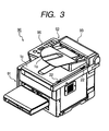
- Figs. 1 to 3 are external perspective views of a copying machine.
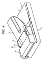
- Fig. 4 is a perspective view of the image reading apparatus.
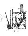
- Fig. 5 is a sectional view along a conveying direction of recording paper of the copying machine shown in Fig. 1.
- a copying machine 90 has an image reading apparatus 92 above an image reading apparatus 91 serving also as an apparatus main body.
- the copying machine 90 is adapted to record image information, which is read by the image reading apparatus 92, on the recording paper P as an image with the image recording apparatus 91 in the case of a copy mode, and to record image data from the outside on the recording paper P as an image with the image recording apparatus 91 in the case of a print mode.
- the image recording apparatus 91 irradiates a photosensitive drum 37 serving as an image bearing member with a laser beam from an optical system 31, which is based upon image information read from the original D in the image reading apparatus 92 or image information sent from the outside, to form an electrostatic latent image on the photosensitive drum 37.
- an image forming portion serving as image forming means which is constituted in a form of a cartridge such as a process cartridge 38
- the image recording apparatus 91 develops the electrostatic latent image formed on the photosensitive drum 37 with a developer (toner) to form a toner image.
- the image recording apparatus 91 conveys the recording paper P with a recording paper supply portion 39, which is disposed at the bottom of the image recording apparatus 91, and a conveying portion 33, and supplies the recording paper P to an image forming portion of the process cartridge 38.
- a transfer device 34 transfers the toner image on the photosensitive drum 37 to the recording paper P.
- a fixing device 35 pressurizes and heats the recording paper P to fix the toner image on the recording paper P.
- the recording paper P is discharged to a tray 32 by a sheet discharge roller 36.
- the image reading apparatus 92 includes an original reading/conveying portion 93, a reading portion unit 94, and an original slider unit 95.
- the reading portion unit 94 includes a platen glass 3 on which the original D or an opened book can be mounted, a sheet glass 4 on which the original D passes automatically, and reading means such as a close contact type image sensor 5 (in this embodiment, a close contact type image sensor is used).
- the original slider unit 95 is a portion where a user arranges to mount originals.
- a platen white background plate 2 which brings the original D into close contact with the platen glass 3 when a user mounted the original D on the platen glass 3, is attached to a lower surface of an original platen 1.
- the original slider unit 95 which is provided with the original platen 1 and the platen white background plate 2, is provided in the reading portion unit 94 so as to be able to rotate with a hinge 22 (see Fig. 3) as a rotation center to open an upper surface of the platen glass 3, and place the original D or the opened book on the upper surface of the platen glass 3.
- An original mounting stand 1a on which plural originals D can be mounted is provided above the original platen 1.
- a pair of movable sliders 1b is provided to the original mounting stand 1a along a direction perpendicular to a conveying direction of the original D (width direction of the original D). The user can arrange both ends of the original D, which is placed on the original mounting stand 1a, by moving the slider 1b.
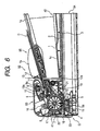
- a U-turn path 7 which is an original conveying path of substantially a U shape identical with an arc of a main roller 6 serving as a conveying rotary member. Attached to this U-turn path 7 are, a separation roller 9 and a separation pat 10, an original presence/absence sensor 11 which detects the presence or absence of the original D, the main roller 6 for conveying the original D and opposed biasing rotary members such as rollers 16, 17, 18, and 19, discharge means such as a sheet discharge roller 12 and an opposed roller 12a, a not-shown original edge sensor for detecting a leading edge and a trailing edge of the original D, and the like. Diameters B2, B3, B4, and B5 of the rollers 16, 17, 18, and 19 are set smaller than a diameter B1 of the main roller 6.
- the U-turn path 7 is formed of an external peripheral original guide 20, which forms an external periphery from the conveying roller 16 to the sheet discharge roller 12, and an internal peripheral guide 21, which forms an internal periphery from the conveying roller 16 to the sheet discharge roller 12.
- a part of the internal peripheral original guide 21 along the main roller 6 is formed in an arc smaller than that of the main roller 6 so as not to be an obstacle to conveyance of the original D by the main roller 6.
- the close contact type image sensor 5 which is arranged on the opposite side of the original reading/conveying portion 93 via the platen glass 3 and the sheet glass 4 (arranged below the platen glass 3 and the sheet glass 4), is adapted to irradiate an image information surface of the original D with light from an LED array serving as a light source, to focus reflected light, which is reflected on'the image information surface, on a sensor element with a SELFOC lens (trademark), and to read image information on the image information surface.
- SELFOC lens trademark
- This close contact type image sensor 5 is adapted to move in a direction of an arrow A shown in Fig. 6 (horizontal direction of Fig. 6).
- the close contact type image sensor 5 is adapted to, in reading the original D or the opened book placed on the platen glass 3 mounted by the user, scan the part below the platen glass 3 on the right side of Fig. 6 to read information on the original D or the book.
- the close contact type image sensor 5 is adapted to, in reading the original D in the original reading/conveying portion 93, that is, in reading the original D automatically sent to the sheet glass 4, stop at a reading position such as a reading line 5a to sequentially read the originals D to be conveyed one after another.
- the user sets the original D on the original mounting stand 1a of the original reading/conveying portion 93 from the right side of the original mounting stand 1a with a read image surface of the original D facing upward. Then, the leading edge of the original D is received by an original stopper 13. In addition, the original presence/absence sensor 11 detects that the original D has been mounted on the original mounting stand 1a.
- the separation roller 9 cooperates with a friction member such as the separation pat 10 to separate the originals D one by one, and conveys the originals D sequentially from the one at the top to the U-turn path 7.
- the separation roller 9 and the separation pat 10 are examples of separation means.
- the main roller 6, the upstream conveying roller 17, the pre-reading conveying roller 18, the post-reading conveying roller 19, the close contact type image sensor 5, the sheet glass 4, the sheet discharge roller 12, the opposed roller 12a, and the like shown in Fig. 6 constitute a sheet-like original reading mechanism 41 for reading a sheet-like original.
- the part of the main roller 6, the upstream conveying roller 17, and the sheet discharge roller 12 is adapted so as to be rotatable to the left in Fig. 6 leaving the pre-reading conveying roller 18, the post-reading conveying roller 19, the close contact type image sensor 5, the sheet glass 4, and the opposed roller 12a behind.
- the sheet glass 4 is opened to make it possible to perform sheet jam treatment.
- the original slider unit 95 provided with the original platen 1 and the platen white background plate 2, the platen glass 3, the close contact type image sensor 5, and the like constitute a book-like original reading mechanism 42 in which an image sensor moves below the platen glass 3 to read the original D or the opened book mounted on the platen glass 3.
- the original slider unit 95 is adapted to be rotated by the hinge 22 (see Fig. 3) to be able to open the platen glass 3. Note that the original slider unit 95 is adapted to rotate separately from the sheet-like original reading mechanism 41.
- the separated original D is conveyed along the U-turn path 7 by the main roller 6, the upstream conveying roller 16 and the upstream conveying roller 17, and the pre-reading conveying roller 18, and is further conveyed to the reading line 5a of the close contact type image sensor 5 located immediately below the sheet glass 4.
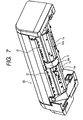
- Fig. 7 is a perspective view of the original reading/conveying portion 93 viewed from a direction of an arrow G shown in Fig. 6, in which a part of components are not shown.
- the original D is conveyed on the sheet glass 4 by the rotation of the main roller 6 while being pressed against the sheet glass 4 by the main roller 6.
- the pair of reading white background plates 14 are pushed by biasing means such as a spring 23 to press the original D against the sheet glass 4 such that the original D does not lift from the sheet glass 4.
- a pressing force of this spring 23 is a force in a degree of not reducing a conveying speed of the original D.
- the reading white background plates 14 instead of providing the spring 23, it is also possible to form the reading white background plates 14 with an elastic member or the like and to impart elasticity to the reading white background plates 14 themselves to press the original D to the sheet glass 4 by means of the elasticity. Lifting of the original D can be prevented by the elasticity inherent in the reading white background plates 14 to read an image on the original D surely.
- a guide surface 14a substantially along an arc surface of the main roller 6 is formed such that the original D can be guided smoothly.
- the original D can be read smoothly by the guide surface 14a guiding the original D to the reading line 5a.
- a length (L) along the axial direction of the main roller 6 is set shorter than a length in a direction crossing the conveying direction of the original D (width of the original D). Consequently, the main roller 6 is adapted to come into contact with only a central part of the original D (in this embodiment, approximately 20 mm wide) rather than the entire reading width of the original D. Then, the reading white background plates 14 are provided on both sides of the main roller 6 so as to nip the main roller 6. The reading white background plates 14 are adapted to come into contact with an area other than the part where the main roller 6 is in contact with the original D.
- a not-shown white reference sheet stuck on the platen glass 3 is detected by the close contact type image sensor 5 arranged below the platen glass 3 to adopt a white reference. Then, at least a surface of the reading white background plates 14 opposed to the close contact type image sensor 5 is colored white to cause the color to function as a background color at the time of reading the original D to prevent offset. A peripheral surface 6a of the main roller 6 is also colored white. As described above, the reading white background plates 14 are provided with the function of pressing the original D to bring the original D into close contact with the sheet glass 4 and the function as a conveyance guide for guiding the original D.
- the original D When the original D has passed the reading line 5a and the image thereon is started to be read by the close contact type image sensor 5, the original D is picked up by a slope member 15 provided on the downstream side of the sheet glass 4, conveyed by the main roller 6 and the post-reading conveying roller 19, and is fed to a part between the sheet discharge roller 12 and the opposed roller 12a.
- the original reading/conveying portion 93 is adapted to press the original D against the main roller 6 with the respective rollers 16, 17, 18, and 19 to convey the original D with the main roller 6.
- the image reading apparatus 92 of this embodiment has a characteristic in that the original D passing the reading line 5a, that is, the original D being read is always conveyed at a uniform speed.
- the diameters of the pre-reading conveying roller 18 and the post-reading conveying roller 19 are set as small as possible to be smaller than the diameters of the upstream conveying rollers 16 and 17. Therefore, the pre-reading conveying roller 18 and the post-reading conveying roller 19 can be brought as close as possible to the reading line 5a existing on the sheet glass 4.
- the image reading apparatus 92 of this embodiment presses the original D against the main roller 6 in the vicinity of the reading line 5a with the pre-reading conveying roller 18 and the post-reading conveying roller 19, the original D can be pressed against the main roller 6 for a longer period of time than that in the past, the play of the original D is reduced, and reading accuracy of an image on the original D can be improved.
- the pre-reading conveying roller 18 presses the original D against the main roller 6 for a long period of time, the image on the original D can be read up to the very trailing edge of the original D without decreasing the reading accuracy of the image on the original D.
- the pre-reading conveying roller 18 and the post-reading conveying roller 19 are set the same, since pre-reading conveying roller 18 and the post-reading conveying roller 19 rotate at the same rotating speed with respect to the main roller 6, the original D is conveyed smoothly. Further, if the diameters of the pre-reading conveying roller 18 and the post-reading conveying roller 19 are set different, the pre-reading conveying roller 18 and the post-reading conveying roller 19 can be brought close to the reading line 5a in accordance with a structure around the rollers. In particular, if the diameter of the pre-reading conveying roller 18 is set smaller than the diameter of the post-reading conveying roller 19, the pre-reading conveying roller 18 can be brought as close as possible to the reading line 5a. Thus, it becomes possible to bring the trailing edge of the original D into pressed-contact against the main roller 6, and the reading accuracy of the original D can be improved.
- the image reading apparatus 92 ends the reading of image information with the close contact type image sensor 5 at a position to which the original D is conveyed by a predetermined amount from the position where the trailing edge of the original D is detected.
- the original D is discharged to a discharged sheet stacking section such as an upper surface 1c of the original platen 1 also serving as an original discharge stand by the sheet discharge roller 12 and the opposed roller 12a.
- the image reading apparatus 92 repeats the above-mentioned reading operation with the original reading/conveying portion 93 and the reading portion unit 94 until the original presence/absence sensor 11 detects the absence of the original D.
- An image reading apparatus is adapted to nip a sheet having an image formed thereon with a main roller and conveying rollers, the conveying rollers being in contact with this main roller, to convey the sheet along the main roller to a reading line opposed to a lowermost point of the main roller, and to read the image with an image sensor for reading an image, and includes reading white background plates which press the sheet against the reading line on both sides of the main roller.
Landscapes
- Engineering & Computer Science (AREA)
- Multimedia (AREA)
- Signal Processing (AREA)
- Physics & Mathematics (AREA)
- General Physics & Mathematics (AREA)
- Facsimiles In General (AREA)
- Facsimile Scanning Arrangements (AREA)
Applications Claiming Priority (2)
| Application Number | Priority Date | Filing Date | Title |
|---|---|---|---|
| JP2002301147 | 2002-10-15 | ||
| JP2002301147A JP2004140474A (ja) | 2002-10-15 | 2002-10-15 | 画像読取装置 |
Publications (2)
| Publication Number | Publication Date |
|---|---|
| EP1429196A2 true EP1429196A2 (fr) | 2004-06-16 |
| EP1429196A3 EP1429196A3 (fr) | 2010-12-15 |
Family
ID=32105009
Family Applications (1)
| Application Number | Title | Priority Date | Filing Date |
|---|---|---|---|
| EP03023078A Withdrawn EP1429196A3 (fr) | 2002-10-15 | 2003-10-14 | Appareil de lecture d'images et appareil de formation d'images l'utilisant |
Country Status (4)
| Country | Link |
|---|---|
| US (1) | US6985692B2 (fr) |
| EP (1) | EP1429196A3 (fr) |
| JP (1) | JP2004140474A (fr) |
| CN (1) | CN100338533C (fr) |
Families Citing this family (8)
| Publication number | Priority date | Publication date | Assignee | Title |
|---|---|---|---|---|
| US7099618B2 (en) * | 2002-10-01 | 2006-08-29 | Brother Kogyo Kabushiki Kaisha | Paper discharge tray |
| USD525291S1 (en) * | 2004-03-15 | 2006-07-18 | Murata Kikai Kabushiki Kaisha | Document feeder |
| US8098411B2 (en) * | 2004-08-31 | 2012-01-17 | Brother Kogyo Kabushiki Kaisha | Image reading apparatus |
| JP2007180844A (ja) * | 2005-12-27 | 2007-07-12 | Canon Inc | 画像読取装置および画像形成装置 |
| JP4854563B2 (ja) * | 2007-03-30 | 2012-01-18 | キヤノン株式会社 | 画像読取装置及び画像形成装置 |
| USD738956S1 (en) * | 2014-01-28 | 2015-09-15 | Hewlett-Packard Development Company, L.P. | Printer with an automatic document feeder input tray |
| EP3213496B1 (fr) | 2014-10-31 | 2022-11-30 | Hewlett-Packard Development Company, L.P. | Cible translatable d'étalonnage de scanner |
| JP1564619S (fr) * | 2016-05-31 | 2017-11-20 |
Family Cites Families (13)
| Publication number | Priority date | Publication date | Assignee | Title |
|---|---|---|---|---|
| US5680203A (en) * | 1994-03-15 | 1997-10-21 | Mita Industrial Co., Ltd. | Image processor having a document conveyor with document suppressing rollers and a document suppressing plate, providing a uniform space for document passage |
| US5819152A (en) * | 1994-11-08 | 1998-10-06 | Nisca Corporation | Compact automatic document feeder with compact document reversing device |
| JP3792052B2 (ja) * | 1998-07-15 | 2006-06-28 | 三井化学株式会社 | 炭化水素化合物および有機電界発光素子 |
| JP2000038234A (ja) | 1998-07-23 | 2000-02-08 | Sharp Corp | 原稿搬送装置 |
| JP3752413B2 (ja) * | 2000-02-02 | 2006-03-08 | ニスカ株式会社 | 用紙搬送装置、及び用紙搬送装置における用紙の供給方法 |
| US6285582B1 (en) * | 2000-03-20 | 2001-09-04 | Epitaxial Technologies, Llc | Two-dimensional resonant tunneling diode memory system |
| US6618575B2 (en) * | 2000-04-20 | 2003-09-09 | Nisca Corporation | Automatic document feeder with a conveying roller and an image reader |
| JP2002116679A (ja) * | 2000-07-31 | 2002-04-19 | Ricoh Co Ltd | 画像形成装置及び画像形成方法 |
| JP2002084424A (ja) | 2000-09-06 | 2002-03-22 | Nisca Corp | 画像読取装置 |
| JP3574068B2 (ja) * | 2000-11-28 | 2004-10-06 | ニスカ株式会社 | シート送り装置及び画像読取装置 |
| JP3715890B2 (ja) * | 2000-12-28 | 2005-11-16 | キヤノン株式会社 | 自動原稿給送装置、及びこれを備えた画像形成装置 |
| JP3599725B2 (ja) * | 2002-08-07 | 2004-12-08 | ニスカ株式会社 | 画像読取装置及び画像読取方法 |
| JP3889684B2 (ja) * | 2002-08-07 | 2007-03-07 | ニスカ株式会社 | 画像読取装置及び画像読取方法 |
-
2002
- 2002-10-15 JP JP2002301147A patent/JP2004140474A/ja active Pending
-
2003
- 2003-09-29 US US10/671,617 patent/US6985692B2/en not_active Expired - Fee Related
- 2003-10-14 EP EP03023078A patent/EP1429196A3/fr not_active Withdrawn
- 2003-10-14 CN CNB2003101012031A patent/CN100338533C/zh not_active Expired - Fee Related
Also Published As
| Publication number | Publication date |
|---|---|
| CN1497370A (zh) | 2004-05-19 |
| US6985692B2 (en) | 2006-01-10 |
| US20040081495A1 (en) | 2004-04-29 |
| JP2004140474A (ja) | 2004-05-13 |
| CN100338533C (zh) | 2007-09-19 |
| EP1429196A3 (fr) | 2010-12-15 |
Similar Documents
| Publication | Publication Date | Title |
|---|---|---|
| JP3504983B2 (ja) | 原稿再生装置 | |
| JP3278341B2 (ja) | ロ−ラ支持装置、シ−ト材給送装置及び原稿読取装置並びに画像記録装置 | |
| US10108128B2 (en) | Automatic document feeder, image reading device incorporating the automatic document feeder, and image forming apparatus incorporating the image reading device with the automatic document feeder | |
| US10044898B2 (en) | Image reading device and image forming apparatus incorporating the image reading device | |
| JP4176100B2 (ja) | 画像形成装置 | |
| US7199910B2 (en) | Original feeding apparatus, original reading apparatus, and image forming apparatus | |
| US6985692B2 (en) | Image reading apparatus and image forming apparatus provided with the same | |
| US10131512B2 (en) | Document feeder and image forming apparatus incorporating the document feeder | |
| JP3818105B2 (ja) | 原稿読取装置 | |
| JP4970196B2 (ja) | 画像読取装置及び画像形成装置 | |
| JP4306985B2 (ja) | 画像読取装置 | |
| US8400685B2 (en) | Image reading device and image forming apparatus having the same, and methods thereof | |
| JP4266475B2 (ja) | 画像読取装置 | |
| US20250264840A1 (en) | Sheet conveyance apparatus, image reading apparatus, and image forming apparatus | |
| JP7837750B2 (ja) | シート搬送装置、及びこれを備えた画像読取装置、画像形成装置 | |
| JP2003252468A (ja) | 給紙装置及び画像形成装置 | |
| JP2000356910A (ja) | 画像形成装置 | |
| JP2004136997A (ja) | 画像読取装置 | |
| US20240017945A1 (en) | Image reading apparatus and image forming apparatus including the same | |
| JP3584145B2 (ja) | シート搬送装置及び画像読取装置 | |
| JP3378123B2 (ja) | 原稿分離搬送装置 | |
| JP3420479B2 (ja) | 画像読取装置及び画像形成装置 | |
| JP3814382B2 (ja) | 画像読取装置及び画像形成装置 | |
| JP2002220125A (ja) | 画像入力装置 | |
| JP2001245102A (ja) | 読取センサ及び画像読取装置及び画像形成装置 |
Legal Events
| Date | Code | Title | Description |
|---|---|---|---|
| PUAI | Public reference made under article 153(3) epc to a published international application that has entered the european phase |
Free format text: ORIGINAL CODE: 0009012 |
|
| AK | Designated contracting states |
Kind code of ref document: A2 Designated state(s): AT BE BG CH CY CZ DE DK EE ES FI FR GB GR HU IE IT LI LU MC NL PT RO SE SI SK TR |
|
| AX | Request for extension of the european patent |
Extension state: AL LT LV MK |
|
| PUAL | Search report despatched |
Free format text: ORIGINAL CODE: 0009013 |
|
| AK | Designated contracting states |
Kind code of ref document: A3 Designated state(s): AT BE BG CH CY CZ DE DK EE ES FI FR GB GR HU IE IT LI LU MC NL PT RO SE SI SK TR |
|
| AX | Request for extension of the european patent |
Extension state: AL LT LV MK |
|
| 17P | Request for examination filed |
Effective date: 20110615 |
|
| 17Q | First examination report despatched |
Effective date: 20110714 |
|
| AKX | Designation fees paid |
Designated state(s): DE ES FR GB IT |
|
| STAA | Information on the status of an ep patent application or granted ep patent |
Free format text: STATUS: THE APPLICATION HAS BEEN WITHDRAWN |
|
| 18W | Application withdrawn |
Effective date: 20111123 |