EP1429360A1 - Dispositif de protection pour moteur à l'état solide - Google Patents
Dispositif de protection pour moteur à l'état solide Download PDFInfo
- Publication number
- EP1429360A1 EP1429360A1 EP03257641A EP03257641A EP1429360A1 EP 1429360 A1 EP1429360 A1 EP 1429360A1 EP 03257641 A EP03257641 A EP 03257641A EP 03257641 A EP03257641 A EP 03257641A EP 1429360 A1 EP1429360 A1 EP 1429360A1
- Authority
- EP
- European Patent Office
- Prior art keywords
- resistor
- isolator
- solid state
- resistors
- motor protector
- Prior art date
- Legal status (The legal status is an assumption and is not a legal conclusion. Google has not performed a legal analysis and makes no representation as to the accuracy of the status listed.)
- Granted
Links
Images



Classifications
-
- H—ELECTRICITY
- H01—ELECTRIC ELEMENTS
- H01H—ELECTRIC SWITCHES; RELAYS; SELECTORS; EMERGENCY PROTECTIVE DEVICES
- H01H61/00—Electrothermal relays
- H01H61/002—Structural combination of a time delay electrothermal relay with an electrothermal protective relay, e.g. a start relay
Definitions
- This invention relates generally to protection devices for electric motors and more particularly to such protectors employing solid state protection PTC (positive temperature coefficient of resistance) elements.
- PTC positive temperature coefficient of resistance
- Electric motors utilize a variety of protectors to avoid degradation of the winding insulation during abusive locked rotor conditions.
- Permanent magnet motors applied in the automotive industry utilize bimetallic or polymer PTC protectors mounted on the brush card, which are connected in series with the motor windings. This arrangement promotes detection of elevated locked rotor versus normal running currents and increasing ambient temperature within the motor housing. The combination of internal I 2 r heating and increasing ambient temperature drives the protectors to interrupt the electric circuit which limits the winding temperature to an acceptable level.
- FIG. 1 An example of a prior art polymer PTC protector particularly adapted for use with a 14 Vdc window lift motor application is shown in Fig. 1 in which a thin, e.g., approximately 0.010 inch thick, polymer chip 1 having metal foil current collectors 1 a on opposite face surfaces is sandwiched between and soldered to relatively thick, e.g., 0.031 inch thick, copper or brass terminals 2 to produce the correct trip time response curves.
- the thick terminals are used to heat sink the polymer PTC chip during transient locked rotor conditions to extend initial trip times at elevated ambient temperature (reference 80°C) to avoid nuisance tripping.
- the current sensitivity of the chip is designed to work with the motor's increasing internal ambient temperature during fixed locked rotor conditions to keep the winding temperature below 250-300°C. Trip times at low voltage, low ambient and low current commutation typically take several minutes so that increasing internal ambient temperature is relied on to trip the polymer PTC chip.
- the winding temperature of proposed 42V automotive operating system motors can increase 300°C in 10 seconds due to design modifications required for normal operation at 42 Vdc.
- protectors cannot utilize the motor's internal ambient temperature to drive the tripping action to be effective since the accelerated winding's temperature rise will cause the winding insulation to melt prior to raising the motor protector's temperature mounted on the brush card.
- Another complication relates to the phenomena of the polymer PTC experiencing torque performance degradation wherein the PTC resistance increases by some 40% after the initial switch and reset operation of the PTC element. It is postulated that this is caused by carbon particles in the polymer not achieving 100% realignment. The resistance shift can be even greater than 40% immediately after the supply voltage is removed producing greater transient motor performance degradation and nuisance trip conditions. Thus, safety applications must be made with the polymer PTC in its lower resistivity state producing the lowest level of I 2 r heating and nuisance trip analysis must be performed with the polymer PTC in its highest resistivity state.
- a solid state motor protector comprises a polymer PTC chip in series with a fixed resistor; producing a variety of desirable performance attributes to achieve locked rotor protection at low voltage, ambient and current conditions while avoiding nuisance trips during transient locked rotor conditions at elevated voltage, ambient and current conditions.
- a fixed resistor and a serially connected polymer PTC resistor are stacked with a spring member between opposing terminal plate members crimped to an isolator separating the terminal members.
- a second embodiment comprises a cup-shaped terminal whose sidewall is insert molded in an isolator ring forming a cavity which receives a fixed resistor and a serially connected polymer resistor along with a spring. The cavity is closed by another cup-shaped terminal crimped to the isolator ring.
- a third embodiment comprises a plate-like isolator formed with an opening which receives a polymer PTC chip and with elongated spiraled terminal/fixed resistor elements received on opposite face surfaces of the isolator and attached to the polymer PTC chip.
- Another embodiment comprises a device providing instantaneous reverse direction capability by utilizing diodes to control the flow of current through an additional PTC chip and fixed resistor within the assembly, as the driving voltage is reversed.
- Still another embodiment comprises a polymer PTC chip sandwiched between a pair of fixed resistors and provided with three terminals for use as a protector for protecting the main and start windings of a single phase motor during locked rotor conditions.
- Yet another embodiment comprises a stack of PTC polymer chips connected in series in which current passing through the entire stack will drive one chip to switch with the remaining chips functioning as fixed resistors with a linear TCR temperature coefficient of resistivity within the application ambient temperature range.
- the two functions of current sensing and voltage blocking are separated providing an additional degree of freedom to adjust the shape of the current response curve which is advantageous to the application.
- the PTC component is designed to block the maximum supply voltage while providing maximum adiabatic trip times at extreme ampere overloads and the fixed resistor is utilized to define the assemblies' ultimate trip and initial trip time performance characteristics by externally heating the polymer PTC component via conduction and convection heat transfer.
- Removing resistance from the PTC component and reducing its "rate of temperature rise" extends the initial trip time at extreme percentage overloads, reducing nuisance trip operation during transient locked rotor conditions. Taken alone, this action results in loss of current sensitivity at low ampere levels, which would degrade locked rotor safety performance at minimum ambient, voltage and ampere conditions.
- the fixed resistor is added to produce the appropriate ultimate trip performance to carry normal operational ampere levels and adjust the current response curve at intermediate percentage overload conditions necessary for locked rotor safety across extreme voltage, ambient and commutation conditions.
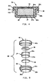
- a motor protector 10 particularly useful with high voltage (e.g., 42 Vdc) automotive systems made in accordance with a first embodiment of the invention, comprises a polymer PTC chip 12 having metal foil current collectors (not shown) on opposite face surfaces thereof electrically connected in series with a fixed resistance resistor 14 having contact surfaces 14a on opposite face surfaces therof.
- a generally rectangular sidewall formed of electrically insulative material such as a thermoplastic polymer serves as an isolator 16 separating top and bottom terminal plates 18, 20, respectively, formed of suitable electrically conductive material such as nickel zinc plated steel.
- PTC chip 12 fixed resistor 14 and an electrically conductive spring 22 of steel, beryllium copper or other suitable material are aligned by the isolator and stacked between the terminals which are suitably attached to isolator 16 as by crimping sidewalls 18a, 20a, bending portions of the sidewall sidewalls into corresponding recesses 16a having retainer ledges 16b at the terminal side of respective recesses on opposite sides of the isolator.
- Terminals 18, 20 are provided with terminal tabs 18b, 20b, respectively, for connection in a circuit energizing a motor to be protected.
- Spring 22 produces sufficient force to hold the component stack together and provide sufficient electrical contact.
- the spring could be formed from one or both terminals as by stamping a spring tab and forming it toward the internal component, i.e., PTC chip 12 and fixed resistor 14.
- Different ratings can be provided within the same package envelope by modifying the bulk resistivity of fixed resistor 14 and PTC chip 12 and by removing material from polymer PTC chip 12, for example, by changing the configuration from a square to a circular shape or by blanking holes in various shapes within PTC chip 12. Additionally, the arrangement of the parts can be changed by placing spring 22 between fixed resistor 14 and PTC chip 12 to modify the rate of heat transfer and associated trip time.
- Motor protector 30 is particularly useful for automotive applications employing small motors such as motors used for door locks.
- Motor protector 30 is a button cell type having an insert molded member 32 having a terminal portion 32a and a generally annular isolator portion 32b providing structural integrity to the package and an external electrical connection surface.
- a generally cylindrical fixed resistor 34 shown with suitable electrical contact surface 34a, generally cylindrical polymer PTC resistor element 36, having current collectors on opposed face surfaces but not separately shown for clarity of illustration, and a suitable electrically conductive spring member 38 are received within the cavity formed in insert molded member 32.
- Terminal portion 32a preferably is formed with an outwardly, radially extending flange which is insert molded in flange portion 32c to structurally interact with crimped terminal member 40 to improve the structural integrity of the motor protector.
- Motor protector 30 can be made having an overall diameter as small as 10mm or less for use where available space is extremely limited or locked rotor current sensitivity below 1 amp is required.
- Motor protector 50 of this embodiment comprises an electrically insulative polymer, plate-like case member 52 having a central PTC element receiving opening 52a therethrough.
- Case member 52 is formed with a raised margin 52b around its perimeter, leaving an opening 52c, on each face surface for receiving a respective combination terminal and fixed resistor members 54, 56.
- Members 54, 56 are formed of a selected resistance material and of suitable configuration, such as the oblong or flattened spiral and having an inner distal end portion 54a, 56a.
- Members 54, 56 are attached to case member 52 as by staking spaced apart portions of margins 52b, the edge of each respective member 54, 56 to hold the component stack together and distal end portions 54a, 56a are step resistance welded to PTC current collectors on the face surfaces of polymer PTC resistor 58 configured to be received within opening 52a of case 52.
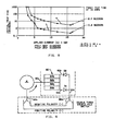
- a protector made in accordance with the invention has improved initial trip times at high currents compared to a prior art protector as reflected in the graph of Fig. 8.
- the graph comprises curves a and b of initial trip time in seconds versus applied current in amperes at 42 volts and +80°C ambient.
- the protector made in accordance with the invention comprises PTC1, a circular polymer PTC element having a diameter of 0.500 inch serially and thermally connected to a fixed resistor R.
- the prior art protector comprises PTC2, a polymer PTC element having a diameter of 0.250 inch.
- Curve b of the prior art protector reflects an initial trip time in 0.2 seconds at 16 amps while curve a of a protector having a serially connected polymer PTC element and fixed resistor reflects an initial trip time in 2.4 at 16 amps with equivalent ultimate trip attributes to provide locked rotor safety at low voltage, ambient and ampere conditions.
- the protector displaying curve a complies with a typical 1.5 second minimum trip time specification to avoid nuisance trip during transient locked rotor conditions.
- a 6:1 locked rotor to run current ratio is typical of 42 Vdc high power window lift and windshield wiper applications; promoting the need to extend initial trip times at high percent overloads to avoid nuisance trip during transient locked rotor conditions.
- both the prior art protector and the protector made in accordance with the invention would have the same current carrying ability during high torque conditions due to equivalent ultimate trip values; however, the PTC 2 prior art protector is significantly more prone to nuisance trip during high percentage overload transient locked rotor conditions associated with its faster response curve as compared to the PTC1+R curve a of a protector made in accordance with the invention.
- the combination of the fixed composition resistor and polymer PTC chip provides more consistent ultimate trip performance versus ambient temperature conditions since the temperature coefficient of resistivity (TCR) value of the assembly is reduced proportional to the percentage of the composition resistor to the total of the two resistors utilized in the assembly.
- TCR temperature coefficient of resistivity
- Fig. 9 shows a motor protector 60 made in accordance with the invention used in a motor reversing circuit, useful for example with window lift motors for instantaneous reverse direction capability during transient locked rotor conditions to free trapped or pinched body parts for example.
- the circuit diagram shows a motor M turning in a counterclockwise direction, motor protector 60 and a double throw, double pole switch 70a, 70b connected to a battery.
- Motor protector 60 is a two terminal device comprising parallel circuits each having a fixed resistor 62a, 62b, respectively, a polymer PTC resistor 64a, 64b, respectively, a first terminal 60a connected between fixed resistors 62a , 62b, a respective diode, D1, D2 connected to outer current collectors or terminal layers 60b, 60c on polymer PTC resistors 64a, 64b, and a second terminal 60d connecting to two diodes.
- the diodes in each parallel circuit are reversed to control current flow through the respective fixed and polymer PTC resistor pairs based on the supply voltage polarity produced in a double throw, double pole switch 66a, 66b.
- switch 66a, 66b is in the solid line position forward biasing diode D1 providing current flow through the lower combined resistor components 62a, 64a as shown in the diagram and the motor producing counterclockwise rotation of the motor. Reversing the switch position as shown in the dashed lines will forward bias diode D2 and provide current flow through the upper combined resistor components 62b, 64b as shown in the diagram and the motor producing a clockwise motor rotation.
- the solid line switch position will forward bias diode D1 and allow locked rotor current to flow through fixed resistor 62a, PTC resistor 64a of the D1 branch and the motor windings.
- PTC resistor 64a will switch to its high resistances state driven by I 2 r heating in fixed resistor 62a and PTC resistor 64a and reduce the ampere level by several orders of magnitude providing safe winding temperatures.
- a protector having only one branch of the circuit could not be "reverse polarity" energized to reverse the motor's direction until the voltage is removed and the PTC resistor allowed to cool below its switch temperature which may take several seconds or even minutes.
- diode D2 will be forward biased and instantly allow current flow through fixed resistor 62b and PTC resistor 64b in the D2 branch and the motor resulting in clockwise rotation and reverse direction operation.
- the fixed resistor and PTC resistor pairs must be in close proximity, i.e., closely thermally coupled, to promote heat transfer from the switched to non-switched PTC resistor components in the event of locked rotor condition in both directions.
- the initial locked rotor conditions elevates the winding temperature above ambient allowing less time for the second PTC resistor to actuate during an instantaneous reverse direction locked rotor condition.
- the close thermal coupling will reduce the initial trip time of the second PTC resistor during reverse direction locked rotor conditions due to the heat transferred from the fixed and PTC resistors of the first branch circuit in addition to the I 2 r heating generated in the second branch circuit.
- polymer PTC resistors 62a, 62b are shown in the center of the stack of resistors connected to terminal 60a, this structure can be reversed by placing fixed resistors 64a, 64b in the center connected to terminal 60a. Further, the connection of the diodes and terminal d can be reversed with terminal 66a connected to the motor.
- Fig. 10 shows another preferred embodiment of the invention in which protector 70 comprises a single PTC resistor 72 electrically connected and sandwiched between a pair of fixed resistors 74, 74a.
- a terminal lead 70a, 70c is connected to the outer face surface of respective fixed resistors 74, 74a and a third terminal 70b is a common terminal connected between PTC resistor 72 and fixed resistor 74a.
- Protector 70 is shown connected to a single phase motor with terminals 70a, 70b connected across the main winding of the motor and terminals 70a, 70c connected across the start winding to provide protection for the windings during locked rotor conditions.
- the values of resistors 74, 74a are selected as required for specified operation. It is preferred, when used in such applications that PTC resistor 72 be formed of ceramic material to provide improved durability in the event of long periods (e.g., weeks) of locked rotor conditions, or the like and for voltage blocking capability at typical conditions for A/C motors.
- Motor protector 80 made in accordance with this embodiment, comprises a serially connected stack of polymer PTC chips 82a, 82b, 82c and 82d.
- one PTC chip will serve as the voltage blocking device while the remaining serve as fixed resistance heating components.
- Current passing through the entire stack of PTC chips will drive one PTC chip to switch under the influence of boundary conditions and starting resistance.
- the switched PTC chip will reduce the ampere level by several orders of magnitude allowing the adjacent PTC chips to cool.
- the adjacent PTC chips will then be heated by the switched PTC chip keeping the adjacent PTC chips below their switch temperature. As a result, the adjacent chips will not experience the typical 40% resistance shift characteristics of switched PTC polymer materials.
- the non-switching PTC chips act like fixed resistors with a linear TCR within the application ambient temperature range.
- Polymer and carbon blended resistors can be designed specifically for this type of application to minimize the TCR value over the application temperature range since the material systems would not have to withstand the exponential resistance increase and power dissipation associated with switching polymer PTC materials.
- the low TCR characteristics would provide resistance stability for optimum motor torque performance.
- a high temperature polymer material filled with conductive particles can be designed for TCR stability up to the switching temperature of the adjacent polymer PTC chip material.
- the pseudo fixed low TCR polymer resistor heats the PTC chip during ampere overloads to produce the desired trip time response.
- a protector made in accordance with this embodiment used with a 42V window lift motor utilized four rectangular shape polymer PTC chips in series (0.250 inch by 0.750 inch) to successfully protect the motor during locked rotor conditions and avoid nuisance trip at elevated ambient temperature conditions.
- Figs. 12 and 12a show a modified embodiment in which protector 90 comprises a first polymer PTC layer 90a having a first selected temperature and thickness sandwiched between second and third polymer PTC layers 90b, 90c having a second higher switch temperature and thickness.
- Current collectors such as foils of nodular nickel plated copper 90d, 90e are shared with layers 90a, 90b and 90a, 90c, respectively, while separate current collectors 90f and 90g, which can be formed in the same manner and of the same material as the shared collectors, are provided for the outer face of layers 90b, 90c, respectively.
- Protector 90 is formed by laminating the layers together to make a particularly cost effective protector.
- a protector 90 for an application having a maximum voltage of 30 Vdc, maximum current of 15 amps, resistivity equal to 0.75 ohm-cm at 20°C ambient and resistance equal to 0.183 ohm +/- 0.037 at 20°C ambient is a protector 90 measuring 9.30mm by 7.50mm and a height (thickness) of 1.90mm.
- Central switching layer 90a is formed of 120°C switch temperature polymer PTC 0.30mm thick and outer layers 90b, 90c each formed of a higher switch temperature, e.g., 300°C polymer PTC 0.70mm thick.
- the current collectors are nodular (i.e., roughened) nickel plated copper foil 0.05mm in thickness. It will be understood that, if desired, the Fig. 12 protector could be made having only one layer 90b or 90c and variations of material thickness and resistivity.
- the normal operating resistance of a polymer PTC chip i.e., the resistance of the chip when at room temperature
- combining a fixed resistor with a polymer PTC resistor significantly reduces both of these issues since the resistivity of the fixed resistor does not significantly change as a result of the overload condition.
- a 0.250 ohm protector made in accordance with the invention has a 2 ampere ultimate trip characteristic at room ambient conditions, requiring 1 watt to elevate the PTC to its switching temperature.
- the fixed resistor is designed with two-thirds of the product resistance (0.167 ohms) and the polymer PTC is designed with one-third of the product resistance (0.083 ohms).
- Alternate percent shifts can be achieved based on the fixed vs. PTC resistance ratios utilized within the protector.
- this resistance shift could be further reduced by providing protectors with PTC that have already been overload shifted; as the fixed resistor provides ohmic and current sensitivity stability to ensure locked rotor safety performance.
- the 40% resistance shift may eventually return to its original value, this process may take several months under specific conditions to occur. Therefore, the safety application must be made with the polymer PTC in its lowest resistivity state, producing the least I 2 r heating.
- the four stack PTC assembly produces an ohmic range of +/- 10% or 0.440 ⁇ to 0.360 ⁇ ; based on a +/- 4 sigma distribution.
- the benefits of the stacked sigma advantage can be combined with the single PTC experiencing trip jump resistance shift of +40% to further improve motor performance.
- the stacked PTC assembly produces a minimum to maximum resistance range equal to 33% (.480 .360) x 100 / .360), while the prior art approach produces a 100% minimum to maximum range (0.640 - 0.320) x 100 / 0.320; inducing greater motor performance degradation.
Landscapes
- Thermistors And Varistors (AREA)
Applications Claiming Priority (2)
| Application Number | Priority Date | Filing Date | Title |
|---|---|---|---|
| US318960 | 2002-12-13 | ||
| US10/318,960 US7038896B2 (en) | 2002-12-13 | 2002-12-13 | Solid state motor protector |
Publications (2)
| Publication Number | Publication Date |
|---|---|
| EP1429360A1 true EP1429360A1 (fr) | 2004-06-16 |
| EP1429360B1 EP1429360B1 (fr) | 2006-04-26 |
Family
ID=32325986
Family Applications (1)
| Application Number | Title | Priority Date | Filing Date |
|---|---|---|---|
| EP03257641A Expired - Lifetime EP1429360B1 (fr) | 2002-12-13 | 2003-12-04 | Dispositif de protection pour moteur à l'état solide |
Country Status (4)
| Country | Link |
|---|---|
| US (1) | US7038896B2 (fr) |
| EP (1) | EP1429360B1 (fr) |
| JP (1) | JP2004201494A (fr) |
| DE (1) | DE60304809T2 (fr) |
Cited By (1)
| Publication number | Priority date | Publication date | Assignee | Title |
|---|---|---|---|---|
| EP2306469A4 (fr) * | 2008-06-06 | 2014-07-09 | Tyco Electronics Japan G K | Dispositif à ctp |
Families Citing this family (12)
| Publication number | Priority date | Publication date | Assignee | Title |
|---|---|---|---|---|
| US7161779B2 (en) * | 2003-12-12 | 2007-01-09 | Lear Corporation | Anti-pinch and electrical motor protection device |
| KR20070076008A (ko) * | 2006-01-17 | 2007-07-24 | 센서스앤드컨트롤스코리아 주식회사 | 개선된 폭발 방지 구조를 갖는 과부하 보호 장치 |
| US7535136B2 (en) * | 2006-02-22 | 2009-05-19 | Emerson Electric Co. | Protector mounting apparatus for protector mounted on the windings of a motor |
| US20070211443A1 (en) * | 2006-03-09 | 2007-09-13 | Rockwell Automation Technologies, Inc. | System and method for postponing application of customizing components in a final drive |
| US8492943B2 (en) * | 2006-10-31 | 2013-07-23 | Emerson Electric Co. | Protector mounting apparatus for protector mounted adjacent the windings of a motor |
| US8581686B2 (en) * | 2009-03-24 | 2013-11-12 | Tyco Electronics Corporation | Electrically activated surface mount thermal fuse |
| US8289122B2 (en) | 2009-03-24 | 2012-10-16 | Tyco Electronics Corporation | Reflowable thermal fuse |
| US8493081B2 (en) | 2009-12-08 | 2013-07-23 | Magna Closures Inc. | Wide activation angle pinch sensor section and sensor hook-on attachment principle |
| US9234979B2 (en) | 2009-12-08 | 2016-01-12 | Magna Closures Inc. | Wide activation angle pinch sensor section |
| US8854784B2 (en) | 2010-10-29 | 2014-10-07 | Tyco Electronics Corporation | Integrated FET and reflowable thermal fuse switch device |
| JP5936900B2 (ja) * | 2011-09-06 | 2016-06-22 | 株式会社ミツバ | 電動モータ |
| CN112373268A (zh) * | 2020-11-19 | 2021-02-19 | 宜宾凯翼汽车有限公司 | 一种hvac总成ptc高压接插件固定结构 |
Citations (6)
| Publication number | Priority date | Publication date | Assignee | Title |
|---|---|---|---|---|
| US3878501A (en) * | 1974-01-02 | 1975-04-15 | Sprague Electric Co | Asymmetrical dual PTCR package for motor start system |
| US3955170A (en) * | 1974-11-29 | 1976-05-04 | Texas Instruments Incorporated | Solid state switch |
| US4092573A (en) * | 1975-12-22 | 1978-05-30 | Texas Instruments Incorporated | Motor starting and protecting apparatus |
| GB2015823A (en) * | 1977-11-15 | 1979-09-12 | Texas Instruments Inc | Thermal relays |
| US4467310A (en) * | 1983-10-03 | 1984-08-21 | Northern Telecom Limited | Telephone subscriber line battery feed resistor arrangements |
| US4792877A (en) * | 1987-08-17 | 1988-12-20 | General Motors Corporation | Electric motor armature current control circuit |
Family Cites Families (10)
| Publication number | Priority date | Publication date | Assignee | Title |
|---|---|---|---|---|
| US3673538A (en) * | 1969-12-05 | 1972-06-27 | Texas Instruments Inc | Composite thermistor temperature sensor having step-function response |
| US3914727A (en) * | 1974-01-02 | 1975-10-21 | Sprague Electric Co | Positive-temperature-coefficient-resistor package |
| US4475138A (en) * | 1980-04-21 | 1984-10-02 | Raychem Corporation | Circuit protection devices comprising PTC element |
| US4780598A (en) * | 1984-07-10 | 1988-10-25 | Raychem Corporation | Composite circuit protection devices |
| US4901186A (en) * | 1988-06-06 | 1990-02-13 | Therm-O-Disc, Incorporated | Temperature compensated thermal protector |
| US5303115A (en) * | 1992-01-27 | 1994-04-12 | Raychem Corporation | PTC circuit protection device comprising mechanical stress riser |
| US5537288A (en) * | 1994-03-10 | 1996-07-16 | Hewlett-Packard Company | PTC switch protected termination resistor |
| CN1135570C (zh) * | 1997-06-04 | 2004-01-21 | 泰科电子有限公司 | 电路保护器件 |
| US6462643B1 (en) * | 1998-02-16 | 2002-10-08 | Matsushita Electric Industrial Co., Ltd. | PTC thermistor element and method for producing the same |
| US6854176B2 (en) * | 1999-09-14 | 2005-02-15 | Tyco Electronics Corporation | Process for manufacturing a composite polymeric circuit protection device |
-
2002
- 2002-12-13 US US10/318,960 patent/US7038896B2/en not_active Expired - Lifetime
-
2003
- 2003-12-04 DE DE60304809T patent/DE60304809T2/de not_active Expired - Lifetime
- 2003-12-04 EP EP03257641A patent/EP1429360B1/fr not_active Expired - Lifetime
- 2003-12-12 JP JP2003414157A patent/JP2004201494A/ja active Pending
Patent Citations (6)
| Publication number | Priority date | Publication date | Assignee | Title |
|---|---|---|---|---|
| US3878501A (en) * | 1974-01-02 | 1975-04-15 | Sprague Electric Co | Asymmetrical dual PTCR package for motor start system |
| US3955170A (en) * | 1974-11-29 | 1976-05-04 | Texas Instruments Incorporated | Solid state switch |
| US4092573A (en) * | 1975-12-22 | 1978-05-30 | Texas Instruments Incorporated | Motor starting and protecting apparatus |
| GB2015823A (en) * | 1977-11-15 | 1979-09-12 | Texas Instruments Inc | Thermal relays |
| US4467310A (en) * | 1983-10-03 | 1984-08-21 | Northern Telecom Limited | Telephone subscriber line battery feed resistor arrangements |
| US4792877A (en) * | 1987-08-17 | 1988-12-20 | General Motors Corporation | Electric motor armature current control circuit |
Cited By (1)
| Publication number | Priority date | Publication date | Assignee | Title |
|---|---|---|---|---|
| EP2306469A4 (fr) * | 2008-06-06 | 2014-07-09 | Tyco Electronics Japan G K | Dispositif à ctp |
Also Published As
| Publication number | Publication date |
|---|---|
| US7038896B2 (en) | 2006-05-02 |
| EP1429360B1 (fr) | 2006-04-26 |
| JP2004201494A (ja) | 2004-07-15 |
| US20040114286A1 (en) | 2004-06-17 |
| DE60304809T2 (de) | 2007-05-16 |
| DE60304809D1 (de) | 2006-06-01 |
Similar Documents
| Publication | Publication Date | Title |
|---|---|---|
| EP1429360B1 (fr) | Dispositif de protection pour moteur à l'état solide | |
| JP3609741B2 (ja) | パック電池 | |
| US5296996A (en) | Device for motor and short-circuit protection | |
| US4701824A (en) | Protected refrigerator compressor motor systems and motor protectors therefor | |
| KR100693057B1 (ko) | 전지팩 및 그 제조 방법 | |
| CN102007561B (zh) | 电路保护装置 | |
| EP0090491A2 (fr) | Dispositif miniature de protection de circuit électrique | |
| EP0346262A2 (fr) | Protecteur thermique compensé en température | |
| US4136323A (en) | Miniature motor protector | |
| JPH07282701A (ja) | 自己保持型保護装置 | |
| EP1933350B1 (fr) | Dispositif de protection pour véhicules automobiles | |
| EP0363746B1 (fr) | Dispositif de protection contre les surintensités pour réseaux électriques et appareils | |
| US7532101B2 (en) | Temperature protection device | |
| US7666544B2 (en) | Connection device for electric accumulator | |
| GB1604111A (en) | Overload prevention circuit for an electric motor | |
| JP6626004B2 (ja) | ブレーカの製造方法とこのブレーカを備える電池パックの製造方法 | |
| CN118899137A (zh) | 用于高电压预充电电路的集成异质热敏电阻布置 | |
| EP0304196B1 (fr) | Circuit de surveillance de courant d'un induit de moteur électrique | |
| CN118471735A (zh) | 依赖温度的开关 | |
| JPH0580088B2 (fr) | ||
| US5889453A (en) | Relay with overload protection | |
| JP4368039B2 (ja) | 自己発熱素子を有する温度ヒューズとこの温度ヒューズを内蔵するパック電池 | |
| JP2593913B2 (ja) | 無接点リレー装置 | |
| JPH10208909A (ja) | Ptc素子を用いた限流器およびこの限流器を備えた遮断器 | |
| KR100586574B1 (ko) | 정온도계수 물질층이 접합된 바이메탈 플레이트 및 이를이용한 과전류 차단소자 |
Legal Events
| Date | Code | Title | Description |
|---|---|---|---|
| PUAI | Public reference made under article 153(3) epc to a published international application that has entered the european phase |
Free format text: ORIGINAL CODE: 0009012 |
|
| AK | Designated contracting states |
Kind code of ref document: A1 Designated state(s): AT BE BG CH CY CZ DE DK EE ES FI FR GB GR HU IE IT LI LU MC NL PT RO SE SI SK TR |
|
| AX | Request for extension of the european patent |
Extension state: AL LT LV MK |
|
| 17P | Request for examination filed |
Effective date: 20041021 |
|
| 17Q | First examination report despatched |
Effective date: 20041117 |
|
| AKX | Designation fees paid |
Designated state(s): DE FR GB |
|
| GRAP | Despatch of communication of intention to grant a patent |
Free format text: ORIGINAL CODE: EPIDOSNIGR1 |
|
| GRAS | Grant fee paid |
Free format text: ORIGINAL CODE: EPIDOSNIGR3 |
|
| GRAA | (expected) grant |
Free format text: ORIGINAL CODE: 0009210 |
|
| AK | Designated contracting states |
Kind code of ref document: B1 Designated state(s): DE FR GB |
|
| REG | Reference to a national code |
Ref country code: GB Ref legal event code: FG4D |
|
| REF | Corresponds to: |
Ref document number: 60304809 Country of ref document: DE Date of ref document: 20060601 Kind code of ref document: P |
|
| ET | Fr: translation filed | ||
| REG | Reference to a national code |
Ref country code: GB Ref legal event code: 732E |
|
| PLBE | No opposition filed within time limit |
Free format text: ORIGINAL CODE: 0009261 |
|
| STAA | Information on the status of an ep patent application or granted ep patent |
Free format text: STATUS: NO OPPOSITION FILED WITHIN TIME LIMIT |
|
| 26N | No opposition filed |
Effective date: 20070129 |
|
| REG | Reference to a national code |
Ref country code: FR Ref legal event code: TP |
|
| REG | Reference to a national code |
Ref country code: GB Ref legal event code: 732E |
|
| REG | Reference to a national code |
Ref country code: FR Ref legal event code: TP |
|
| PGFP | Annual fee paid to national office [announced via postgrant information from national office to epo] |
Ref country code: FR Payment date: 20111205 Year of fee payment: 9 |
|
| REG | Reference to a national code |
Ref country code: FR Ref legal event code: ST Effective date: 20130830 |
|
| PG25 | Lapsed in a contracting state [announced via postgrant information from national office to epo] |
Ref country code: FR Free format text: LAPSE BECAUSE OF NON-PAYMENT OF DUE FEES Effective date: 20130102 |
|
| PGFP | Annual fee paid to national office [announced via postgrant information from national office to epo] |
Ref country code: GB Payment date: 20141124 Year of fee payment: 12 |
|
| PGFP | Annual fee paid to national office [announced via postgrant information from national office to epo] |
Ref country code: DE Payment date: 20141222 Year of fee payment: 12 |
|
| REG | Reference to a national code |
Ref country code: DE Ref legal event code: R119 Ref document number: 60304809 Country of ref document: DE |
|
| GBPC | Gb: european patent ceased through non-payment of renewal fee |
Effective date: 20151204 |
|
| PG25 | Lapsed in a contracting state [announced via postgrant information from national office to epo] |
Ref country code: GB Free format text: LAPSE BECAUSE OF NON-PAYMENT OF DUE FEES Effective date: 20151204 Ref country code: DE Free format text: LAPSE BECAUSE OF NON-PAYMENT OF DUE FEES Effective date: 20160701 |