EP1430229B1 - Befestigungselement - Google Patents
Befestigungselement Download PDFInfo
- Publication number
- EP1430229B1 EP1430229B1 EP02777017A EP02777017A EP1430229B1 EP 1430229 B1 EP1430229 B1 EP 1430229B1 EP 02777017 A EP02777017 A EP 02777017A EP 02777017 A EP02777017 A EP 02777017A EP 1430229 B1 EP1430229 B1 EP 1430229B1
- Authority
- EP
- European Patent Office
- Prior art keywords
- section
- fastener
- punching
- piercing
- tubular
- Prior art date
- Legal status (The legal status is an assumption and is not a legal conclusion. Google has not performed a legal analysis and makes no representation as to the accuracy of the status listed.)
- Expired - Lifetime
Links
- 229910052751 metal Inorganic materials 0.000 claims abstract description 32
- 239000002184 metal Substances 0.000 claims abstract description 32
- 238000005520 cutting process Methods 0.000 claims abstract description 25
- 230000007704 transition Effects 0.000 claims abstract description 5
- 230000015572 biosynthetic process Effects 0.000 claims description 7
- 238000003825 pressing Methods 0.000 claims description 7
- 238000004080 punching Methods 0.000 description 65
- 230000035939 shock Effects 0.000 description 11
- 238000000034 method Methods 0.000 description 6
- 238000004519 manufacturing process Methods 0.000 description 4
- 239000000463 material Substances 0.000 description 4
- 229910045601 alloy Inorganic materials 0.000 description 3
- 239000000956 alloy Substances 0.000 description 3
- 230000001154 acute effect Effects 0.000 description 2
- 238000007493 shaping process Methods 0.000 description 2
- 229910000838 Al alloy Inorganic materials 0.000 description 1
- 101001108245 Cavia porcellus Neuronal pentraxin-2 Proteins 0.000 description 1
- 229910000861 Mg alloy Inorganic materials 0.000 description 1
- 229910000831 Steel Inorganic materials 0.000 description 1
- 229910052782 aluminium Inorganic materials 0.000 description 1
- XAGFODPZIPBFFR-UHFFFAOYSA-N aluminium Chemical compound [Al] XAGFODPZIPBFFR-UHFFFAOYSA-N 0.000 description 1
- 239000011324 bead Substances 0.000 description 1
- 238000010276 construction Methods 0.000 description 1
- 230000001419 dependent effect Effects 0.000 description 1
- 239000011159 matrix material Substances 0.000 description 1
- 238000005096 rolling process Methods 0.000 description 1
- 239000007787 solid Substances 0.000 description 1
- 239000010959 steel Substances 0.000 description 1
- 238000003860 storage Methods 0.000 description 1
- 238000005482 strain hardening Methods 0.000 description 1
- 230000000007 visual effect Effects 0.000 description 1
Images


Classifications
-
- F—MECHANICAL ENGINEERING; LIGHTING; HEATING; WEAPONS; BLASTING
- F16—ENGINEERING ELEMENTS AND UNITS; GENERAL MEASURES FOR PRODUCING AND MAINTAINING EFFECTIVE FUNCTIONING OF MACHINES OR INSTALLATIONS; THERMAL INSULATION IN GENERAL
- F16B—DEVICES FOR FASTENING OR SECURING CONSTRUCTIONAL ELEMENTS OR MACHINE PARTS TOGETHER, e.g. NAILS, BOLTS, CIRCLIPS, CLAMPS, CLIPS OR WEDGES; JOINTS OR JOINTING
- F16B37/00—Nuts or like thread-engaging members
- F16B37/04—Devices for fastening nuts to surfaces, e.g. sheets, plates
- F16B37/06—Devices for fastening nuts to surfaces, e.g. sheets, plates by means of welding or riveting
-
- B—PERFORMING OPERATIONS; TRANSPORTING
- B23—MACHINE TOOLS; METAL-WORKING NOT OTHERWISE PROVIDED FOR
- B23P—METAL-WORKING NOT OTHERWISE PROVIDED FOR; COMBINED OPERATIONS; UNIVERSAL MACHINE TOOLS
- B23P19/00—Machines for simply fitting together or separating metal parts or objects, or metal and non-metal parts, whether or not involving some deformation; Tools or devices therefor so far as not provided for in other classes
- B23P19/04—Machines for simply fitting together or separating metal parts or objects, or metal and non-metal parts, whether or not involving some deformation; Tools or devices therefor so far as not provided for in other classes for assembling or disassembling parts
- B23P19/06—Screw or nut setting or loosening machines
- B23P19/062—Pierce nut setting machines
-
- F—MECHANICAL ENGINEERING; LIGHTING; HEATING; WEAPONS; BLASTING
- F16—ENGINEERING ELEMENTS AND UNITS; GENERAL MEASURES FOR PRODUCING AND MAINTAINING EFFECTIVE FUNCTIONING OF MACHINES OR INSTALLATIONS; THERMAL INSULATION IN GENERAL
- F16B—DEVICES FOR FASTENING OR SECURING CONSTRUCTIONAL ELEMENTS OR MACHINE PARTS TOGETHER, e.g. NAILS, BOLTS, CIRCLIPS, CLAMPS, CLIPS OR WEDGES; JOINTS OR JOINTING
- F16B37/00—Nuts or like thread-engaging members
- F16B37/04—Devices for fastening nuts to surfaces, e.g. sheets, plates
- F16B37/06—Devices for fastening nuts to surfaces, e.g. sheets, plates by means of welding or riveting
- F16B37/062—Devices for fastening nuts to surfaces, e.g. sheets, plates by means of welding or riveting by means of riveting
- F16B37/065—Devices for fastening nuts to surfaces, e.g. sheets, plates by means of welding or riveting by means of riveting by deforming the material of the nut
-
- F—MECHANICAL ENGINEERING; LIGHTING; HEATING; WEAPONS; BLASTING
- F16—ENGINEERING ELEMENTS AND UNITS; GENERAL MEASURES FOR PRODUCING AND MAINTAINING EFFECTIVE FUNCTIONING OF MACHINES OR INSTALLATIONS; THERMAL INSULATION IN GENERAL
- F16B—DEVICES FOR FASTENING OR SECURING CONSTRUCTIONAL ELEMENTS OR MACHINE PARTS TOGETHER, e.g. NAILS, BOLTS, CIRCLIPS, CLAMPS, CLIPS OR WEDGES; JOINTS OR JOINTING
- F16B37/00—Nuts or like thread-engaging members
- F16B37/04—Devices for fastening nuts to surfaces, e.g. sheets, plates
- F16B37/06—Devices for fastening nuts to surfaces, e.g. sheets, plates by means of welding or riveting
- F16B37/062—Devices for fastening nuts to surfaces, e.g. sheets, plates by means of welding or riveting by means of riveting
- F16B37/068—Devices for fastening nuts to surfaces, e.g. sheets, plates by means of welding or riveting by means of riveting by deforming the material of the support, e.g. the sheet or plate
-
- Y—GENERAL TAGGING OF NEW TECHNOLOGICAL DEVELOPMENTS; GENERAL TAGGING OF CROSS-SECTIONAL TECHNOLOGIES SPANNING OVER SEVERAL SECTIONS OF THE IPC; TECHNICAL SUBJECTS COVERED BY FORMER USPC CROSS-REFERENCE ART COLLECTIONS [XRACs] AND DIGESTS
- Y10—TECHNICAL SUBJECTS COVERED BY FORMER USPC
- Y10T—TECHNICAL SUBJECTS COVERED BY FORMER US CLASSIFICATION
- Y10T29/00—Metal working
- Y10T29/49—Method of mechanical manufacture
- Y10T29/49826—Assembling or joining
- Y10T29/49833—Punching, piercing or reaming part by surface of second part
- Y10T29/49835—Punching, piercing or reaming part by surface of second part with shaping
- Y10T29/49837—Punching, piercing or reaming part by surface of second part with shaping of first part
Definitions
- the present invention relates to a fastener with a Attachment section and a tubular punching and / or riveting section, wherein the punching and / or riveting section for mounting the Fastener is designed to a sheet metal part and the attachment portion designed for attachment of an article to the sheet metal part is, wherein in the region of the transition from the mounting portion in the Punching and / or riveting a radially and / or conically extending contact surface is provided, which may be anti-rotation features and the tubular punching and / or riveting section at its free front end on the radially inner side a cone-shaped, in the direction of the free front end diverging oblique or Cutting surface and on the radially outer side of a rounded shock and Drawing surface, wherein the sloping or cutting surface and the impact and pulling surface at an annular end edge at the free end of the front of the punching and / or riveting section.
- Fasteners of this type are either self-piercing in Inserted sheet metal part, so that the element has a punching and / or riveting having. But you can also introduced into pre-punched sheets be, with the Vorlochung often using a so-called provisional punch, the sheet metal part immediately before or pierces during attachment of the fastener. This possibility exists only with fasteners that act as a hollow body element, For example, mother elements are formed, since the punch the Must penetrate fastener.
- the effective size of the fixing section is the strength which is required by the fastener as such to understand. For example, if the fastener is a bolt member is equal to the effective size of the attachment section the outer diameter of the threaded cylinder, i. at a fastener with a metric thread of 5 mm diameter the effective size of the fixing section is also 5 mm. at a fastener with a threaded cylinder of 6 mm diameter the effective size of the fixing section is 6 mm, etc. If it is a parent, the effective size is the same determined, i.
- Inner diameter is the effective size of the attachment section as 8 to assume mm.
- the outer diameter of the shaft part is considered as the effective size.
- the effective size of the attachment portion 10 is 10 mm.
- the shape of the cone-shaped, in the direction of the free front end divergent cutting surface and on the radially outer side of the Punching and / or riveting section provided rounded shock and pull surface are very precise in the known fasteners in order to fulfill the respective tasks.
- the cutting surface was designed as a cone-shaped Surface formed, which is the hypotenuse of an imaginary rectangular Triangle has a leg length perpendicular to the central longitudinal axis the tubular punching and / or Nietäbitess of, depending on effective size of the fixing section, 0.2 mm to 0.3 mm. sense
- This cone-shaped cutting surface is on the one hand in the production of the stamping to compress it in the radial direction, so that the stamping is clamped in the punching and / or riveting section.
- These Einklemmung stiffens the punching and / or riveting during the subsequent deformation thereof, which is advantageous.
- the rounded shock and pull surface in the known elements has a center of curvature on the inner wall of the punch and / or rivet section was placed, wherein the radius of curvature has a length equal to the radial wall thickness of the tubular punching and / or riveting section corresponds.
- Object of the present invention is to provide a modified form of Specify fasteners of the type mentioned, not or to a much lesser extent leads to the formation of chips, without the otherwise proven mounting methods (with or without pre-punching) must be changed and without the technical values of the achieved connections are degraded, and it is also possible should be to continue to use the previously used matrices.
- the invention provides that the cone-shaped oblique or. Cutting surface the hypotenuse of an imaginary triangular triangle forms with a leg length perpendicular to the central longitudinal axis of the tubular punching and / or riveting of 0.10 mm ⁇ 0.03 mm that the radial wall thickness (R) of the tubular punching and / or riveting in is dimensioned as a function of the effective size of the attachment section, that the rounded abutting and pulling surface has a radius of curvature that is 0.1 mm ⁇ 0.03 mm smaller than the respective radial wall thickness (R) and that the center of curvature of the rounded abutting and pulling surface lies on the surface of an imaginary axis-parallel cylinder, which extends away from the annular end edge in the direction of the attachment portion and at a position along the punching and / or riveting on the surface of the imaginary paraxial cylinder is set so that a tangent to the rounded shock and pulling surface at the annular end
- the chips in principle have three causes. On the one hand They occur when cutting through the sheet metal part. They do, however, occur even when the sheet is pulled up into the tubular collar and they also occur during the punching and / or riveting section in the recess of the die around the drawn tubular collar portion is rolled over.
- This Stehbolzenelemts 150 consists of a shaft part 154, shown here without thread, and a head part 152 with a radial flange and a tubular punching and riveting 156th
- the jacket wall 158 of the tubular Punching and riveting essentially circular cylindrical and ends in a rounded push and pull edge 160 at the free end of the tubular punching and riveting section.
- the inner wall 164 of the tubular punching and riveting section is also substantially cylindrical in this embodiment terminates in a conical cutting surface 166 which is connected to an annular Front edge at the free front end of the punching and riveting section of the rounded Shock and pull edge 160 hits.
- a sheet metal part is produced in a pressing tool 206 supported by a die 180 and it is by means of a pressing tool 210 in the form of the plunger of a press the fastener 150th pressed against the sheet metal part 206 so that, as shown in Fig. 3, a Punch 216 is created and the sheet metal part to a tubular collar 218 (Fig. 4) is pulled.
- the punched joint 216 is within the tubular punching and riveting by a stamp projection 184 pressed the die and the punching and riveting 156 is due the rounded rolling surface 202 of the die 180 radially outwardly about the free front end of the tubular collar 218 to form a Nietbördels rolled until the end position shown in FIG. 8 is reached.
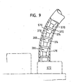
- Fig. 9 shows how a plurality of bolt elements in a row in one Punching 472 a press can be introduced so that at each Stroke the press a bolt element from the punching head in a new sheet metal part stamped and can be riveted with this. Even if the Fig. 7 represents a special shaping of the matrix, this can also be the Have a shape of a rotational body, i. that the levels shown there Stamping areas 220 need not be present.
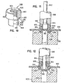
- Figs. 10 to 12 show that a nut member instead of a bolt element can apply and continues to show, as in Although this embodiment, the mother element self-piercing in the Sheet metal part 650 is introduced, the punching but by means of a Ejection pin 642 then pushed out and over a middle Channel 638 of the template 632 is disposed of.
- FIGS. 13 to 18 show, like a nut element 600, in a sheet metal part 650 using a so-called leading puncher 122, the the Vorlochung of the sheet metal part 650 is used, can be used, so that the punching and riveting section here a thrusting and pulling function has, but is not used for punching the sheet metal part.
- fasteners shown provided with a punching and / or riveting section, the its free front end on the radially inner side with a cone-shaped Slanting or cutting surface and on the radially outer side with a Rounded shock and pull edge is provided, with the rounded shock- and pulling edge of the cone-shaped inclined surface to an annular end edge the punching and riveting section meets.
- the present invention is a special training of the punching and riveting section in the area its free front end, which ensures the avoidance of chips.
- Anti-rotation features only need then be provided when in operation the fastener torques must transfer to the sheet metal part, for example, if an object on the sheet metal part by means of a on the mounting portion 702 screwed nut is to be attached, wherein the Screwing the nut due to friction torque on Fastening element is created and collected from the sheet metal part got to. Such torques also arise when removing the nut and also need the connection between the fastener and be carried or transferred to the sheet metal part.
- the tubular punching and / or riveting section has at its free Front end 714 on the radially inner side of a cone-shaped cutting surface 716 and on the radially outer side of a rounded push and pull surface 718, wherein the cutting surface 716 and the shock and pull surface at an annular end edge 720 at the free end of the punch and / or rivet section.
- the tubular punching and / or riveting portion 704 has a circular cylindrical Outside wall 722 and a circular cylindrical inner wall 724, the both concentric with the central longitudinal axis 726 of the fastener are arranged.
- the cone-shaped cutting surface 716 in FIG viewed from a radial cross section the hypotenuse of an imaginary one isosceles, rectangular triangle forms, its equal length Legs are denoted by the reference numerals 717 and 719.
- the Leg 717 corresponds to the imaginary continuation of the inner wall 724 of the punching and / or Nietabitess 704 from the beginning of the oblique or Cutting surface 716 up to the intersection with the imaginary radius, which goes from the annular end edge 720 to the longitudinal axis 726, the portion of this radius being from the annular end edge to the intersection with the imaginary continuation of the inner wall 724 of the punching and / or riveting portion 704 forms the leg 719.
- the legs 717 and 719 each have a leg length in this example of 0.1 mm, this leg length according to the invention 0.1 mm ⁇ 0.03 mm. Since this is preferably a isosceles triangle, but not mandatory is the cone angle of the cone-shaped cutting surface relative to the central longitudinal axis 726 90 °.
- the distance between the annular End edge 720 and the radially inner wall 724 of the tubular Punching and / or riveting section is (radial distance measured at the annular end edge 720) also 0.1 mm.
- the radial wall thickness R of the tubular punching and / or riveting section is in this example a bolt element of size M5 1.25 +/- 0.05 mm.
- the rounded push and pull surface 718 according to the invention a radius of curvature smaller than 0.1 mm ( ⁇ 0.03 mm) is the respective radial wall thickness R (1.25 mm in this example).
- the center of curvature 727 is the (circular) rounded Shock and pulling surface on the surface of an imaginary axis-parallel Cylinder 728, away from the annular end edge 720 extends in the direction of the fastening portion 702.
- this training leads the free end of the punching and / or riveting portion 704, that the Rounded push and pull surface 718 also tangential in the circular cylindrical Exploitation of the tubular rivet section enters.
- the concrete dimensions indicate for a bolt element according to the invention in the size M6, where the radial wall thickness of the punching and / or riveting section 704 also 1.25 mm.
- FIG. 21 is representative of FIGS. 22, 23 and 24. All dimensions are included in the drawings and in mm indicated and therefore the drawing to remove properly.
- the exact shape of the free front end the punching and / or riveting section 704 also for all fasteners covered by this application, including also elements of the designation SBF, SBK; RSF and RSK and at all possible applications of the claimed fasteners (also the applications described above as storage or clip recording or to form a snap connection) and for these types Element can be used when it comes to shavings avoid.
- the functional elements are called all materials that are for the existing SBF, SBK, RSF and RSK elements are used.
- Such Materials include alloys that in the context of cold working the To achieve strength values of class 8 according to Isostandard, for example a 35B2 alloy according to DIN 1654.
- the fasteners thus formed own u.a. for all commercial steel materials for drawable sheet metal parts as well as for aluminum or its alloys.
- Functional elements come from higher-strength magnesium alloys such as eg AM50 in question.
Landscapes
- Engineering & Computer Science (AREA)
- General Engineering & Computer Science (AREA)
- Mechanical Engineering (AREA)
- Insertion Pins And Rivets (AREA)
- Connection Of Plates (AREA)
- Motor Or Generator Frames (AREA)
- Fluid-Damping Devices (AREA)
- Rear-View Mirror Devices That Are Mounted On The Exterior Of The Vehicle (AREA)
Description
dass die gerundete Stoß- und Ziehfläche einen Krümmungsradius aufweist, der 0,1 mm ± 0,03 mm kleiner ist als die jeweilige radiale Wanddicke (R) und dass der Krümmungsmittelpunkt der gerundeten Stoß- und Ziehfläche an der Oberfläche eines gedachten achsparallelen Zylinders liegt, der sich von der ringförmige Stirnkante weg in Richtung des Befestigungsabschnittes erstreckt und an einer Stelle entlang des Stanzund/ oder Nietabschnittes an der Oberfläche des gedachten achsparallelen Zylinders so gelegt ist, dass eine Tangente zu der gerundeten Stoß- und Ziehfläche an der ringförmigen Stirnkante senkrecht zur mittleren Längsachse steht.
- Figuren 1 bis 12
- die Figuren 7 bis 14 und 26 bis 29 aus dem deutschen Patent 34 47 006, die das Verfahren zur Anbringung von Befestigungselementen an Blechteilen in der bekannten Form zeigt, wobei sowohl ein Bolzenelement als auch ein Mutterelement gezeigt werden und bei dem Mutterelement ein Ausstoßstift zur Entfernung des Stanzbutzens zur Anwendung gelangt,
- Figuren 13 bis 18
- die Figuren 7, 8 und 10 bis 13 der DE-PS 34 46 978 C2, die die Anbringung eines Mutterelementes unter Anwendung eines vorlaufenden Lochstempels zeigen,
- Figuren 19, 20
- ein Befestigungselement in Form eines Bolzenelementes nach der vorliegenden Erfindung, und zwar in Form einer Stirnansicht und einer teilweise in Längsrichtung geschnittenen Seitenansicht und
- Figuren 21 - 24
- die Ausbildung des Stanz- und Nietabschnittes im Bereich A der Fig. 20 in bemaßter Form für Bolzenelemente mit Durchmesser M5, M6, M8 bzw. M10.
Claims (7)
- Befestigungselement (700) mit einem Befestigungsabschnitt (702) und einem rohrförmigen Stanz- und/oder Nietabschnitt (704), wobei der Stanz- und/ oder Nietabschnitt zur Anbringung des Befestigungselements an ein Blechteil ausgelegt ist und der Befestigungsabschnitt zur Anbringung eines Gegenstandes an das Blechteil ausgelegt ist, wobei im Bereich des Übergangs vom Befestigungsabschnitt (702) in den Stanz- und/ oder Nietabschnitt eine sich radial und/ oder konusförmig erstreckende Anlagefläche (708) vorgesehen ist, die gegebenenfalls Verdrehsicherungsmerkmale (710, 712) aufweist und der rohrförmige Stanz- und/oder Nietabschnitt an seinem freien Stirnende (714) auf der radial inneren Seite eine konusförmige, in Richtung des freien Stirnendes divergierende Schräg- bzw. Schneidfläche (716) und auf der radial äußeren Seite eine gerundete Stoß- und Ziehfläche (718) aufweist, wobei die Schräg- bzw. Schneidfläche (716) und die Stoß- und Ziehfläche (718) sich an einer ringförmigen Stirnkante (720) am freien Stirnende des Stanz- und/oder Nietabschnitts (704) treffen,
dadurch gekennzeichnet dass die konusförmige Schräg- bzw. Schneidfläche (716) die Hypotenuse eines gedachten reckeckigen Dreiecks bildet mit einer Schenkellänge senkrecht zur mittleren Längsachse (726) des rohrförmigen Stanz- und/ oder Nietabschnitts (204) von 0,10 mm ± 0,03 mm, dass die radiale Wanddicke (R) des rohrförmigen Stanzund/ oder Nietabschnitts (704) als Funktion der effektiven Größe des Befestigungsabschnittes bemessen ist,
dass die gerundete Stoß- und Ziehfläche (718) einen Krümmungsradius (r) aufweist, der 0,1 mm ± 0,03 mm kleiner ist als die jeweilige radiale Wanddicke (R) und dass der Krümmungsmittelpunkt (727) der gerundeten Stoß- und Ziehfläche (718) an der Oberfläche eines gedachten achsparallelen Zylinders (728) liegt, der sich von der ringförmige Stirnkante (720) weg in Richtung des Befestigungsabschnittes (702) erstreckt und an einer Stelle entlang des Stanz- und/oder Nietabschnittes (704) an der Oberfläche des gedachten achsparallelen Zylinders (728) so gelegt ist, dass eine Tangente (730) zu der gerundeten Stoß- und Ziehfläche (718) an der ringförmigen Stirnkante (720) senkrecht zur mittleren Längsachse (726) steht. - Befestigungselement nach Anspruch 1,
dadurch gekennzeichnet, dass die radiale Wanddicke (R) des rohrförmigen Stanz- und/oder Nietabschnitts (704) als Funktion der effektiven Größe des Befestigungsabschnittes wie folgt bemessenist: Größe von 5 mm R = 1,25 ± 0,05 mmGröße von 6 mm R = 1,25 ± 0,05 mmGröße von 8 mm R = 1,50 ± 0,05 mmGröße von 10 mm R = 1,82 ± 0,05 mm. - Befestigungselement nach Anspruch 1 oder 2,
dadurch gekennzeichnet, dass es sich um ein Bolzenelement handelt und der Befestigungsabschnitt mit einem Gewindezylinder versehen oder versehbar ist, dessen Außendurchmesser die effektive Größe des Befestigungsabschnitts bildet. - Befestigungselement nach Anspruch 1 oder 2,
dadurch gekennzeichnet, dass der Befestigungsabschnitt sich als Schaftteil darstellt, beispielsweise zur Aufnahme einer drehbaren Lagerung, oder mit Formmerkmalen zur Bildung einer Schnappverbindung oder mit einer Aufnahme für eine Federklammer, wobei der Außendurchmesser des Schaftteils die effektive Größe des Befestigungsabschnitts bildet. - Befestigungselement nach Anspruch 1 oder 2,
dadurch gekennzeichnet, dass es sich um ein Mutterelement handelt, bei dem der Befestigungsabschnitt eine Bohrung aufweist, die mit einem Innengewinde versehen ist oder zur Bildung eines Innengewindes gedacht ist, beispielsweise unter Anwendung einer gewindeschneidenden oder gewindeformenden Schraube, wobei der Außendurchmesser des Gewindezylinders die effektive Größe des Befestigungsabschnitts bestimmt bzw. dieser entspricht. - Befestigungselement nach Anspruch 1 oder 2,
dadurch gekennzeichnet dass es sich um ein hohles Element handelt, das zur Aufnahme einer drehbaren Welle im Befestigungsabschnitt eine Bohrung aufweist, wobei der Durchmesser der Bohrung die effektive Größe des Befestigungsabschnitts bestimmt. - Befestigungselement nach Anspruch 1 oder 2,
dadurch gekennzeichnet dass es sich um ein hohles Element handelt, das zur Aufnahme einer Klippbefestigung eine Bohrung aufweist und der Durchmesser der Bohrung die effektive Größe des Befestigungsabschnitts bestimmt.
Applications Claiming Priority (3)
| Application Number | Priority Date | Filing Date | Title |
|---|---|---|---|
| DE10147076A DE10147076A1 (de) | 2001-09-25 | 2001-09-25 | Befestigungselement |
| DE10147076 | 2001-09-25 | ||
| PCT/EP2002/010001 WO2003029667A1 (de) | 2001-09-25 | 2002-09-06 | Befestigungselement |
Publications (2)
| Publication Number | Publication Date |
|---|---|
| EP1430229A1 EP1430229A1 (de) | 2004-06-23 |
| EP1430229B1 true EP1430229B1 (de) | 2005-11-30 |
Family
ID=7700126
Family Applications (1)
| Application Number | Title | Priority Date | Filing Date |
|---|---|---|---|
| EP02777017A Expired - Lifetime EP1430229B1 (de) | 2001-09-25 | 2002-09-06 | Befestigungselement |
Country Status (11)
| Country | Link |
|---|---|
| US (1) | US6979160B2 (de) |
| EP (1) | EP1430229B1 (de) |
| JP (1) | JP4245479B2 (de) |
| KR (1) | KR100766454B1 (de) |
| AT (1) | ATE311546T1 (de) |
| BR (1) | BR0212788B1 (de) |
| CA (1) | CA2461268C (de) |
| DE (2) | DE10147076A1 (de) |
| ES (1) | ES2250720T3 (de) |
| MX (1) | MXPA04002656A (de) |
| WO (1) | WO2003029667A1 (de) |
Cited By (4)
| Publication number | Priority date | Publication date | Assignee | Title |
|---|---|---|---|---|
| EP2283965A1 (de) | 2009-08-13 | 2011-02-16 | Profil Verbindungstechnik GmbH & Co. KG | Funktionselement, Verfahren zum Einbringen des Funktionselementes in ein Blechteil sowie Zusammenbauteil |
| DE102013217640A1 (de) | 2013-09-04 | 2015-03-05 | Profil Verbindungstechnik Gmbh & Co. Kg | Verfahren zur Anbringung eines Befestigungselements an ein Werkstück, Kombination einer Scheibe mit einer Matrize sowie Matrize |
| DE102013218548A1 (de) | 2013-09-16 | 2015-03-19 | Profil Verbindungstechnik Gmbh & Co. Kg | Lochstempel sowie Verfahren zum Durchstanzen eines Werkstücks, das als Schaummaterial und/oder als Sandwichmaterial vorliegt, sowie Verfahren zur Herstellung des Lochstempels |
| DE102016114476A1 (de) | 2016-08-04 | 2018-02-08 | Profil Verbindungstechnik Gmbh & Co. Kg | Vorrichtung und Verfahren zur Anbringung von Funktionselementen auf einem Bauteil |
Families Citing this family (27)
| Publication number | Priority date | Publication date | Assignee | Title |
|---|---|---|---|---|
| DE10015239A1 (de) * | 2000-03-27 | 2001-10-04 | Profil Verbindungstechnik Gmbh | Funktionselementanordnung, Funktionselement, Hilfsfügeteil, Zusammenbauteil und Verfahren zur Herstellung eines Zusammenbauteils |
| DE10119505A1 (de) * | 2001-04-20 | 2002-10-24 | Profil Verbindungstechnik Gmbh | Funktionselement zur Anbringung an ein Blechteil, aus diesen hergestelltes Zusammenbauteil sowie Verfahren zur Anbringung des Funktionselements an ein Bauteil |
| DE10249030A1 (de) | 2002-04-19 | 2003-11-06 | Profil Verbindungstechnik Gmbh | Funktionselement zur Anbringung an ein Blechteil, aus diesen hergestelltes Zusammenbauteil sowie Verfahren zur Anbringung des Funktionselements an ein Blechteil |
| US20050111934A1 (en) * | 2003-11-14 | 2005-05-26 | Ladouceur Harold A. | Self-riveting male fastener and panel assembly |
| DE102004020675A1 (de) * | 2004-04-28 | 2005-11-24 | Profil Verbindungstechnik Gmbh & Co. Kg | Verfahren und Vorrichtung zur Anbringung eines Befestigungselements an ein Bauteil, insbesondere an ein Blechteil |
| US20060236536A1 (en) * | 2005-03-28 | 2006-10-26 | Seiko Epson Corporation | Die apparatus, method for producing perforated work plate, perforated work plate, liquid-jet head and liquid-jet apparatus |
| US7480971B2 (en) | 2005-04-28 | 2009-01-27 | Profile Verbindungstechnik Gmbh & Co., Kg | Method and device for mounting a fastener element on a part, particularly a sheet metal part |
| RU2418206C2 (ru) * | 2006-01-05 | 2011-05-10 | Профиль-Фербиндунгстехник Гмбх Унд Ко. Кг | Крепежный элемент, узловая сборка, состоящая из крепежного элемента и детали из листового металла, а также способ закрепления крепежного элемента на детали из листового металла |
| GB0609580D0 (en) * | 2006-05-13 | 2006-06-21 | Henrob Ltd | Self-piercing riveting |
| DE202006008721U1 (de) * | 2006-06-01 | 2007-10-11 | Profil Verbindungstechnik Gmbh & Co. Kg | Nietmutter und Kombination einer Nietmutter mit einem Blechteil |
| DE102006028537B3 (de) * | 2006-06-21 | 2007-05-10 | Singh, Sumanjit, Dr. | Stanzniet und Matrize |
| JP5688568B2 (ja) * | 2008-07-15 | 2015-03-25 | 山野井精機株式会社 | 被加工金属部材に突起を形成する突起形成方法 |
| WO2010059469A1 (en) * | 2008-11-21 | 2010-05-27 | Pem Management, Inc. | Piercing standoff |
| DE102010005404A1 (de) | 2010-01-22 | 2011-07-28 | PROFIL Verbindungstechnik GmbH & Co. KG, 61381 | Führungs- und Setzeinrichtung für Befestigungselemente |
| US8458881B1 (en) * | 2011-11-22 | 2013-06-11 | Ford Global Technologies, Llc | Die with multi-sided cavity for self-piercing riveting process |
| CN103511433A (zh) * | 2012-06-25 | 2014-01-15 | 珠海格力电器股份有限公司 | 铆接螺栓 |
| DE102012017289A1 (de) * | 2012-08-31 | 2014-05-15 | Audi Ag | Einprägeelement insbesondere für das Widerstandsschweißen |
| DE102013217213A1 (de) | 2013-08-28 | 2015-03-05 | Profil Verbindungstechnik Gmbh & Co. Kg | Verfahren zum einstanzen und befestigen eines befestigungselements und entsprechende matrize |
| DE102013217633A1 (de) | 2013-09-04 | 2015-03-05 | Profil Verbindungstechnik Gmbh & Co. Kg | Stanzniet und Verfahren zur Befestigung einzelner Bauteile aneinander, von denen mindestens ein Bauteil durch ein Werkstück aus Verbundmaterial gebildet ist |
| DE102013217632A1 (de) | 2013-09-04 | 2015-03-05 | Profil Verbindungstechnik Gmbh & Co. Kg | Stanzniet sowie Verfahren und Vorrichtungen zur Befestigung einzelner Bauteile aneinander, von denen mindestens ein Bauteil durch ein Werkstück aus Verbundmaterial gebildet ist |
| DE102014201976A1 (de) * | 2014-02-04 | 2015-08-06 | Böllhoff Verbindungstechnik GmbH | Stanzniet |
| DE102016119053A1 (de) * | 2016-10-07 | 2018-04-12 | Gustav Klauke Gmbh | Verfahren zur Herstellung einer mit einem Kabelschuh drehverbundenen Mutter und mit einem Kabelschuh drehverbundene Mutter |
| CA3254953A1 (en) * | 2017-05-09 | 2025-04-24 | Penn Engineering & Manufacturing Corp. | Fastener and installation method for very thin sheets |
| US11009332B2 (en) * | 2019-02-19 | 2021-05-18 | Stanley Black & Decker, Inc. | Tape measure end hook protection |
| DE102019133891A1 (de) * | 2019-12-11 | 2021-06-17 | Profil Verbindungstechnik Gmbh & Co. Kg | Funktionselement |
| DE102021103979A1 (de) | 2020-03-24 | 2021-09-30 | Profil Verbindungstechnik Gmbh & Co. Kg | Nietelement und Zusammenbauteil bestehend aus dem Nietelement und einem Bauteil |
| CN114160743B (zh) * | 2021-11-22 | 2024-10-25 | 苏州雷力紧固技术有限责任公司 | 一种自冲铆连接装置及其铆接方法 |
Family Cites Families (21)
| Publication number | Priority date | Publication date | Assignee | Title |
|---|---|---|---|---|
| US2208532A (en) * | 1938-10-15 | 1940-07-16 | United Carr Fastener Corp | Nut member |
| US3299500A (en) * | 1961-11-28 | 1967-01-24 | Multifastener Corp | Method of making a nut and panel assembly |
| US3276499A (en) * | 1963-12-30 | 1966-10-04 | Republic Steel Corp | Flush-driven self-piercing and clinching nut and method of securing to a member |
| US3878599A (en) * | 1969-07-11 | 1975-04-22 | Multifastener Corp | Method of forming a nut and panel assembly |
| US3894331A (en) * | 1971-03-23 | 1975-07-15 | Leer Koninklijke Emballage | Method of mounting a bushing to a container closure |
| DE3003908C2 (de) * | 1980-02-02 | 1984-10-18 | Profil-Verbindungstechnik Gmbh & Co Kg, 6382 Friedrichsdorf | Stehbolzen mit Stanz- und Nietverhalten |
| US4555838A (en) * | 1983-03-28 | 1985-12-03 | Multifastener Corp. | Method of installing self-attaching fasteners |
| US5067224A (en) * | 1980-02-02 | 1991-11-26 | Multifastener Corporation | Method of installing self-attaching fastener and apparatus |
| US4610072A (en) | 1983-12-21 | 1986-09-09 | Multifastener Corporation | Method of installing a fastener to a panel |
| US4765057A (en) * | 1980-02-02 | 1988-08-23 | Multifastener Corporation | Self-attaching fastener, panel assembly and installation apparatus |
| US4831698A (en) * | 1983-03-28 | 1989-05-23 | Multifastener Corporation | Method of attaching a female element to a panel |
| US5441417A (en) * | 1981-01-28 | 1995-08-15 | Multifastener Corporation | Electrical grounding stud |
| DE3327751A1 (de) * | 1982-08-06 | 1984-02-09 | Avdel Ltd., Welwyn Garden City, Hertfordshire | Verankerungsmutter-befestigungsvorrichtung |
| US6257814B1 (en) * | 1995-08-18 | 2001-07-10 | Profil Verbindungstechnik & Co. | Self-attaching fastener, method of forming same and method of attachment |
| US5868535A (en) * | 1997-08-04 | 1999-02-09 | Multifastener Corporation | Self-riveting fastening element |
| EP1064466B1 (de) * | 1999-01-26 | 2002-03-20 | Richard Bergner Verbindungstechnik GmbH & Co KG | Stanzniet |
| FR2805281B1 (fr) * | 2000-02-23 | 2002-09-27 | Recupac | Procede de valorisation des poussieres d'acieries |
| DE10015239A1 (de) * | 2000-03-27 | 2001-10-04 | Profil Verbindungstechnik Gmbh | Funktionselementanordnung, Funktionselement, Hilfsfügeteil, Zusammenbauteil und Verfahren zur Herstellung eines Zusammenbauteils |
| DE10119505A1 (de) * | 2001-04-20 | 2002-10-24 | Profil Verbindungstechnik Gmbh | Funktionselement zur Anbringung an ein Blechteil, aus diesen hergestelltes Zusammenbauteil sowie Verfahren zur Anbringung des Funktionselements an ein Bauteil |
| DE20113853U1 (de) * | 2001-08-22 | 2001-11-15 | Textron Verbindungstechnik GmbH & Co. oHG, 56567 Neuwied | Selbstlochendes, verdreh- und auspressicher in ein Blech einpressbares Befestigungselement |
| US20030101566A1 (en) * | 2001-12-05 | 2003-06-05 | Ladouceur Harold A. | Self-piercing element, method of attachment and die member |
-
2001
- 2001-09-25 DE DE10147076A patent/DE10147076A1/de not_active Withdrawn
-
2002
- 2002-09-06 KR KR1020047004209A patent/KR100766454B1/ko not_active Expired - Fee Related
- 2002-09-06 WO PCT/EP2002/010001 patent/WO2003029667A1/de not_active Ceased
- 2002-09-06 MX MXPA04002656A patent/MXPA04002656A/es active IP Right Grant
- 2002-09-06 ES ES02777017T patent/ES2250720T3/es not_active Expired - Lifetime
- 2002-09-06 DE DE50205135T patent/DE50205135D1/de not_active Expired - Lifetime
- 2002-09-06 CA CA2461268A patent/CA2461268C/en not_active Expired - Lifetime
- 2002-09-06 EP EP02777017A patent/EP1430229B1/de not_active Expired - Lifetime
- 2002-09-06 BR BRPI0212788-1A patent/BR0212788B1/pt not_active IP Right Cessation
- 2002-09-06 AT AT02777017T patent/ATE311546T1/de not_active IP Right Cessation
- 2002-09-06 US US10/489,792 patent/US6979160B2/en not_active Expired - Lifetime
- 2002-09-06 JP JP2003532850A patent/JP4245479B2/ja not_active Expired - Fee Related
Cited By (8)
| Publication number | Priority date | Publication date | Assignee | Title |
|---|---|---|---|---|
| EP2283965A1 (de) | 2009-08-13 | 2011-02-16 | Profil Verbindungstechnik GmbH & Co. KG | Funktionselement, Verfahren zum Einbringen des Funktionselementes in ein Blechteil sowie Zusammenbauteil |
| DE102009037427A1 (de) | 2009-08-13 | 2011-02-17 | Profil Verbindungstechnik Gmbh & Co. Kg | Funktionselement, Verfahren zum Einbringen des Funktionselementes in ein Blechteil sowie Zusammenbauteil |
| US8608419B2 (en) | 2009-08-13 | 2013-12-17 | Profil-Verbindungstechnik Gmbh & Co. Kg | Functional element, method for an introduction of the functional element into a sheet metal part and also component assembly |
| DE102013217640A1 (de) | 2013-09-04 | 2015-03-05 | Profil Verbindungstechnik Gmbh & Co. Kg | Verfahren zur Anbringung eines Befestigungselements an ein Werkstück, Kombination einer Scheibe mit einer Matrize sowie Matrize |
| EP2845680A1 (de) | 2013-09-04 | 2015-03-11 | Profil Verbindungstechnik GmbH & Co. KG | Verfahren zur Befestigung eines Befestigungselementes an einem Werkstück, Kombination einer Unterlegscheibe mit einer Prägeform sowie Prägeform |
| DE102013218548A1 (de) | 2013-09-16 | 2015-03-19 | Profil Verbindungstechnik Gmbh & Co. Kg | Lochstempel sowie Verfahren zum Durchstanzen eines Werkstücks, das als Schaummaterial und/oder als Sandwichmaterial vorliegt, sowie Verfahren zur Herstellung des Lochstempels |
| EP2863071A1 (de) | 2013-09-16 | 2015-04-22 | Profil Verbindungstechnik GmbH & Co. KG | Locher und Verfahren für das Durchstechen eines Werkstücks, aus Schaummaterial und/oder aus Sandwich-Material und auch ein Verfahren zur Herstellung des Lochers. |
| DE102016114476A1 (de) | 2016-08-04 | 2018-02-08 | Profil Verbindungstechnik Gmbh & Co. Kg | Vorrichtung und Verfahren zur Anbringung von Funktionselementen auf einem Bauteil |
Also Published As
| Publication number | Publication date |
|---|---|
| BR0212788A (pt) | 2004-10-05 |
| KR20040047847A (ko) | 2004-06-05 |
| KR100766454B1 (ko) | 2007-10-15 |
| DE10147076A1 (de) | 2003-04-17 |
| JP2005504243A (ja) | 2005-02-10 |
| US6979160B2 (en) | 2005-12-27 |
| US20050008453A1 (en) | 2005-01-13 |
| MXPA04002656A (es) | 2004-06-18 |
| JP4245479B2 (ja) | 2009-03-25 |
| EP1430229A1 (de) | 2004-06-23 |
| BR0212788B1 (pt) | 2011-02-08 |
| ES2250720T3 (es) | 2006-04-16 |
| CA2461268C (en) | 2010-11-23 |
| CA2461268A1 (en) | 2003-04-10 |
| ATE311546T1 (de) | 2005-12-15 |
| DE50205135D1 (de) | 2006-01-05 |
| WO2003029667A1 (de) | 2003-04-10 |
Similar Documents
| Publication | Publication Date | Title |
|---|---|---|
| EP1430229B1 (de) | Befestigungselement | |
| EP1674741B1 (de) | Ein durch Nieten an ein Blechteil anbringbares Element sowie Zusammenbauteil und Verfahren zur Erzeugung des Zusammenbauteils | |
| EP1806509B1 (de) | Funktionselement, Zusammenbauteil bestehend aus dem Funktionselement und einem Blechteil sowie Verfahren zum Anbringen eines Funktionselements | |
| EP0667936B2 (de) | Verfahren zur herstellung eines auspress- und drehfesten verbundteils durch einpressen eines einpressteils in ein blechteil sowie dafür geeignete einpressteile | |
| DE69507348T2 (de) | Selbstsicherndes Befestigungselement und Verfahren zu dessen Herstellung und Einbau | |
| EP1985408B1 (de) | Funktionselement zur Anbringung an ein Blechteil, aus diesen hergestelltes Zusammenbauteil sowie Verfahren zur Anbringung des Funktionselements an ein Blechteil | |
| EP0464071B1 (de) | Loch- und gewindeformende schraube | |
| DE3003908C2 (de) | Stehbolzen mit Stanz- und Nietverhalten | |
| EP2980426B1 (de) | Zusammenbauteil bestehend aus einem einpresselement und einem blechteil | |
| EP2479442B1 (de) | Funktionselement in Form eines Einpresselements | |
| DE19902461A1 (de) | Mutter mit T-förmigem Querschnitt | |
| EP2412991B1 (de) | Selbststanzendes Mutterelement und Zusammenbauteil bestehend aus dem Mutterelement und einem Blechteil | |
| DE102008052383A1 (de) | Zusammenbauteil bestehend aus einem Befestigungselement und einem Blechteil sowie ein Verfahren zur Herstellung eines solchen Zusammenbauteils | |
| DE102011108224A1 (de) | Funktionselement mit Verdrehsicherungsmerkmalen sowie Zusammenbauteil bestehend aus dem Funktionselement und einem Blechteil | |
| DE19913695A1 (de) | Verfahren, Werkzeug und Stempel zum Verbinden von Bauteilen mit einer Platte | |
| EP0993902A2 (de) | Verfahren zur Anbringung eines Funktionselementes, Matrize, Funktionselement, Zusammenbauteil | |
| EP1165283A1 (de) | Funktionsträgeranordnung | |
| DE10249030A1 (de) | Funktionselement zur Anbringung an ein Blechteil, aus diesen hergestelltes Zusammenbauteil sowie Verfahren zur Anbringung des Funktionselements an ein Blechteil | |
| EP1576295A1 (de) | Stanzniet für eine verbindung an blechen sowie verfahren zum setzen eines derartigen stanzniets | |
| DE102018117131A1 (de) | Selbststanzendes Element und Zusammenbauteil bestehend aus dem Element und einem Blechteil | |
| DE102006062073A1 (de) | Funktionselement, Zusammenbauteil bestehend aus dem Funktionselement und einem Blechteil sowie Verfahren zum Anbringen eines Funktionselements | |
| EP1572392A1 (de) | Vorrichtung zum setzen eines stanzniets in blech | |
| DE102004031379A1 (de) | Verfahren zur Anbringung eines Funktionselementes an ein Bleichteil sowie Zusammenbauteil | |
| EP1379790B1 (de) | Verfahren zur herstellung eines zusammenbauteils bestehend aus einem blechteil und einem gewindestift sowie zusammenbauteil. | |
| DE10241326A1 (de) | Befestigungselement, insbesondere zum Blindnieten |
Legal Events
| Date | Code | Title | Description |
|---|---|---|---|
| PUAI | Public reference made under article 153(3) epc to a published international application that has entered the european phase |
Free format text: ORIGINAL CODE: 0009012 |
|
| 17P | Request for examination filed |
Effective date: 20040317 |
|
| AK | Designated contracting states |
Kind code of ref document: A1 Designated state(s): AT BE BG CH CY CZ DE DK EE ES FI FR GB GR IE IT LI LU MC NL PT SE SK TR |
|
| AX | Request for extension of the european patent |
Extension state: AL LT LV MK RO SI |
|
| GRAP | Despatch of communication of intention to grant a patent |
Free format text: ORIGINAL CODE: EPIDOSNIGR1 |
|
| RTI1 | Title (correction) |
Free format text: FIXING ELEMENT |
|
| GRAS | Grant fee paid |
Free format text: ORIGINAL CODE: EPIDOSNIGR3 |
|
| GRAA | (expected) grant |
Free format text: ORIGINAL CODE: 0009210 |
|
| AK | Designated contracting states |
Kind code of ref document: B1 Designated state(s): AT BE BG CH CY CZ DE DK EE ES FI FR GB GR IE IT LI LU MC NL PT SE SK TR |
|
| PG25 | Lapsed in a contracting state [announced via postgrant information from national office to epo] |
Ref country code: SK Free format text: LAPSE BECAUSE OF FAILURE TO SUBMIT A TRANSLATION OF THE DESCRIPTION OR TO PAY THE FEE WITHIN THE PRESCRIBED TIME-LIMIT Effective date: 20051130 Ref country code: IE Free format text: LAPSE BECAUSE OF FAILURE TO SUBMIT A TRANSLATION OF THE DESCRIPTION OR TO PAY THE FEE WITHIN THE PRESCRIBED TIME-LIMIT Effective date: 20051130 Ref country code: NL Free format text: LAPSE BECAUSE OF FAILURE TO SUBMIT A TRANSLATION OF THE DESCRIPTION OR TO PAY THE FEE WITHIN THE PRESCRIBED TIME-LIMIT Effective date: 20051130 Ref country code: CZ Free format text: LAPSE BECAUSE OF FAILURE TO SUBMIT A TRANSLATION OF THE DESCRIPTION OR TO PAY THE FEE WITHIN THE PRESCRIBED TIME-LIMIT Effective date: 20051130 Ref country code: FI Free format text: LAPSE BECAUSE OF FAILURE TO SUBMIT A TRANSLATION OF THE DESCRIPTION OR TO PAY THE FEE WITHIN THE PRESCRIBED TIME-LIMIT Effective date: 20051130 |
|
| REG | Reference to a national code |
Ref country code: CH Ref legal event code: EP Ref country code: GB Ref legal event code: FG4D Free format text: NOT ENGLISH |
|
| GBT | Gb: translation of ep patent filed (gb section 77(6)(a)/1977) |
Effective date: 20051201 |
|
| REG | Reference to a national code |
Ref country code: IE Ref legal event code: FG4D Free format text: LANGUAGE OF EP DOCUMENT: GERMAN |
|
| REF | Corresponds to: |
Ref document number: 50205135 Country of ref document: DE Date of ref document: 20060105 Kind code of ref document: P |
|
| PG25 | Lapsed in a contracting state [announced via postgrant information from national office to epo] |
Ref country code: DK Free format text: LAPSE BECAUSE OF FAILURE TO SUBMIT A TRANSLATION OF THE DESCRIPTION OR TO PAY THE FEE WITHIN THE PRESCRIBED TIME-LIMIT Effective date: 20060228 Ref country code: SE Free format text: LAPSE BECAUSE OF FAILURE TO SUBMIT A TRANSLATION OF THE DESCRIPTION OR TO PAY THE FEE WITHIN THE PRESCRIBED TIME-LIMIT Effective date: 20060228 Ref country code: GR Free format text: LAPSE BECAUSE OF FAILURE TO SUBMIT A TRANSLATION OF THE DESCRIPTION OR TO PAY THE FEE WITHIN THE PRESCRIBED TIME-LIMIT Effective date: 20060228 Ref country code: BG Free format text: LAPSE BECAUSE OF FAILURE TO SUBMIT A TRANSLATION OF THE DESCRIPTION OR TO PAY THE FEE WITHIN THE PRESCRIBED TIME-LIMIT Effective date: 20060228 |
|
| REG | Reference to a national code |
Ref country code: ES Ref legal event code: FG2A Ref document number: 2250720 Country of ref document: ES Kind code of ref document: T3 |
|
| RAP2 | Party data changed (patent owner data changed or rights of a patent transferred) |
Owner name: PROFIL VERBINDUNGSTECHNIK GMBH & CO. KG |
|
| PG25 | Lapsed in a contracting state [announced via postgrant information from national office to epo] |
Ref country code: PT Free format text: LAPSE BECAUSE OF FAILURE TO SUBMIT A TRANSLATION OF THE DESCRIPTION OR TO PAY THE FEE WITHIN THE PRESCRIBED TIME-LIMIT Effective date: 20060502 |
|
| NLV1 | Nl: lapsed or annulled due to failure to fulfill the requirements of art. 29p and 29m of the patents act | ||
| REG | Reference to a national code |
Ref country code: IE Ref legal event code: FD4D |
|
| ET | Fr: translation filed | ||
| PG25 | Lapsed in a contracting state [announced via postgrant information from national office to epo] |
Ref country code: BE Free format text: LAPSE BECAUSE OF NON-PAYMENT OF DUE FEES Effective date: 20060930 Ref country code: MC Free format text: LAPSE BECAUSE OF NON-PAYMENT OF DUE FEES Effective date: 20060930 Ref country code: LI Free format text: LAPSE BECAUSE OF NON-PAYMENT OF DUE FEES Effective date: 20060930 Ref country code: CH Free format text: LAPSE BECAUSE OF NON-PAYMENT OF DUE FEES Effective date: 20060930 |
|
| PLBE | No opposition filed within time limit |
Free format text: ORIGINAL CODE: 0009261 |
|
| STAA | Information on the status of an ep patent application or granted ep patent |
Free format text: STATUS: NO OPPOSITION FILED WITHIN TIME LIMIT |
|
| 26N | No opposition filed |
Effective date: 20060831 |
|
| REG | Reference to a national code |
Ref country code: GB Ref legal event code: 732E |
|
| REG | Reference to a national code |
Ref country code: CH Ref legal event code: PL |
|
| PG25 | Lapsed in a contracting state [announced via postgrant information from national office to epo] |
Ref country code: AT Free format text: LAPSE BECAUSE OF NON-PAYMENT OF DUE FEES Effective date: 20060906 |
|
| BERE | Be: lapsed |
Owner name: PROFIL VERBINDUNGSTECHNIK G.M.B.H. & CO. KG Effective date: 20060930 |
|
| PG25 | Lapsed in a contracting state [announced via postgrant information from national office to epo] |
Ref country code: EE Free format text: LAPSE BECAUSE OF FAILURE TO SUBMIT A TRANSLATION OF THE DESCRIPTION OR TO PAY THE FEE WITHIN THE PRESCRIBED TIME-LIMIT Effective date: 20051130 |
|
| PG25 | Lapsed in a contracting state [announced via postgrant information from national office to epo] |
Ref country code: TR Free format text: LAPSE BECAUSE OF FAILURE TO SUBMIT A TRANSLATION OF THE DESCRIPTION OR TO PAY THE FEE WITHIN THE PRESCRIBED TIME-LIMIT Effective date: 20051130 Ref country code: LU Free format text: LAPSE BECAUSE OF NON-PAYMENT OF DUE FEES Effective date: 20060906 |
|
| REG | Reference to a national code |
Ref country code: GB Ref legal event code: 732E |
|
| REG | Reference to a national code |
Ref country code: FR Ref legal event code: TP Ref country code: FR Ref legal event code: CD Ref country code: FR Ref legal event code: CA |
|
| PG25 | Lapsed in a contracting state [announced via postgrant information from national office to epo] |
Ref country code: CY Free format text: LAPSE BECAUSE OF FAILURE TO SUBMIT A TRANSLATION OF THE DESCRIPTION OR TO PAY THE FEE WITHIN THE PRESCRIBED TIME-LIMIT Effective date: 20051130 |
|
| REG | Reference to a national code |
Ref country code: FR Ref legal event code: GC |
|
| REG | Reference to a national code |
Ref country code: FR Ref legal event code: GC |
|
| REG | Reference to a national code |
Ref country code: FR Ref legal event code: RG Effective date: 20150206 |
|
| REG | Reference to a national code |
Ref country code: FR Ref legal event code: PLFP Year of fee payment: 15 |
|
| REG | Reference to a national code |
Ref country code: FR Ref legal event code: PLFP Year of fee payment: 16 |
|
| REG | Reference to a national code |
Ref country code: FR Ref legal event code: PLFP Year of fee payment: 17 |
|
| PGFP | Annual fee paid to national office [announced via postgrant information from national office to epo] |
Ref country code: IT Payment date: 20180925 Year of fee payment: 17 |
|
| PGFP | Annual fee paid to national office [announced via postgrant information from national office to epo] |
Ref country code: GB Payment date: 20180919 Year of fee payment: 17 |
|
| PGFP | Annual fee paid to national office [announced via postgrant information from national office to epo] |
Ref country code: ES Payment date: 20181022 Year of fee payment: 17 |
|
| PG25 | Lapsed in a contracting state [announced via postgrant information from national office to epo] |
Ref country code: IT Free format text: LAPSE BECAUSE OF NON-PAYMENT OF DUE FEES Effective date: 20190906 |
|
| GBPC | Gb: european patent ceased through non-payment of renewal fee |
Effective date: 20190906 |
|
| PG25 | Lapsed in a contracting state [announced via postgrant information from national office to epo] |
Ref country code: GB Free format text: LAPSE BECAUSE OF NON-PAYMENT OF DUE FEES Effective date: 20190906 |
|
| PGFP | Annual fee paid to national office [announced via postgrant information from national office to epo] |
Ref country code: FR Payment date: 20200812 Year of fee payment: 19 |
|
| REG | Reference to a national code |
Ref country code: ES Ref legal event code: FD2A Effective date: 20210628 |
|
| PG25 | Lapsed in a contracting state [announced via postgrant information from national office to epo] |
Ref country code: ES Free format text: THE PATENT HAS BEEN ANNULLED BY A DECISION OF A NATIONAL AUTHORITY Effective date: 20190907 |
|
| PGFP | Annual fee paid to national office [announced via postgrant information from national office to epo] |
Ref country code: DE Payment date: 20210727 Year of fee payment: 20 |
|
| PG25 | Lapsed in a contracting state [announced via postgrant information from national office to epo] |
Ref country code: FR Free format text: LAPSE BECAUSE OF NON-PAYMENT OF DUE FEES Effective date: 20210930 |
|
| REG | Reference to a national code |
Ref country code: DE Ref legal event code: R071 Ref document number: 50205135 Country of ref document: DE |