EP1431061B1 - Druckdecke und verfahren zur herstellung derselben - Google Patents
Druckdecke und verfahren zur herstellung derselben Download PDFInfo
- Publication number
- EP1431061B1 EP1431061B1 EP01972543A EP01972543A EP1431061B1 EP 1431061 B1 EP1431061 B1 EP 1431061B1 EP 01972543 A EP01972543 A EP 01972543A EP 01972543 A EP01972543 A EP 01972543A EP 1431061 B1 EP1431061 B1 EP 1431061B1
- Authority
- EP
- European Patent Office
- Prior art keywords
- compressible
- layer
- unvulcanized
- microballoons
- printing blanket
- Prior art date
- Legal status (The legal status is an assumption and is not a legal conclusion. Google has not performed a legal analysis and makes no representation as to the accuracy of the status listed.)
- Expired - Lifetime
Links
- 238000004519 manufacturing process Methods 0.000 title claims description 31
- 239000010410 layer Substances 0.000 claims description 238
- 229920001971 elastomer Polymers 0.000 claims description 132
- 239000005060 rubber Substances 0.000 claims description 132
- 238000007639 printing Methods 0.000 claims description 79
- 239000012790 adhesive layer Substances 0.000 claims description 75
- 239000004744 fabric Substances 0.000 claims description 75
- 238000002844 melting Methods 0.000 claims description 36
- 230000008018 melting Effects 0.000 claims description 36
- 239000003795 chemical substances by application Substances 0.000 claims description 33
- 239000002245 particle Substances 0.000 claims description 20
- 230000003014 reinforcing effect Effects 0.000 claims description 20
- 239000002243 precursor Substances 0.000 claims description 17
- 150000002334 glycols Chemical class 0.000 claims description 12
- 229920001577 copolymer Polymers 0.000 claims description 11
- NLHHRLWOUZZQLW-UHFFFAOYSA-N Acrylonitrile Chemical compound C=CC#N NLHHRLWOUZZQLW-UHFFFAOYSA-N 0.000 claims description 9
- GYCMBHHDWRMZGG-UHFFFAOYSA-N Methylacrylonitrile Chemical compound CC(=C)C#N GYCMBHHDWRMZGG-UHFFFAOYSA-N 0.000 claims description 8
- 238000010030 laminating Methods 0.000 claims description 4
- 239000000853 adhesive Substances 0.000 claims description 3
- 230000001070 adhesive effect Effects 0.000 claims description 3
- 230000035882 stress Effects 0.000 description 43
- MTHSVFCYNBDYFN-UHFFFAOYSA-N diethylene glycol Chemical compound OCCOCCO MTHSVFCYNBDYFN-UHFFFAOYSA-N 0.000 description 33
- 229920000742 Cotton Polymers 0.000 description 19
- 230000000052 comparative effect Effects 0.000 description 19
- 210000004027 cell Anatomy 0.000 description 18
- 239000011800 void material Substances 0.000 description 17
- 239000000203 mixture Substances 0.000 description 14
- 239000000463 material Substances 0.000 description 13
- 238000000034 method Methods 0.000 description 13
- 238000004073 vulcanization Methods 0.000 description 12
- LYCAIKOWRPUZTN-UHFFFAOYSA-N Ethylene glycol Chemical compound OCCO LYCAIKOWRPUZTN-UHFFFAOYSA-N 0.000 description 10
- 239000011159 matrix material Substances 0.000 description 10
- 238000002156 mixing Methods 0.000 description 10
- KFZMGEQAYNKOFK-UHFFFAOYSA-N Isopropanol Chemical compound CC(C)O KFZMGEQAYNKOFK-UHFFFAOYSA-N 0.000 description 9
- 239000011248 coating agent Substances 0.000 description 8
- 238000000576 coating method Methods 0.000 description 8
- 229920000459 Nitrile rubber Polymers 0.000 description 7
- 238000002360 preparation method Methods 0.000 description 7
- 238000010438 heat treatment Methods 0.000 description 6
- 239000003094 microcapsule Substances 0.000 description 6
- 150000003839 salts Chemical class 0.000 description 6
- 238000000638 solvent extraction Methods 0.000 description 6
- YXIWHUQXZSMYRE-UHFFFAOYSA-N 1,3-benzothiazole-2-thiol Chemical compound C1=CC=C2SC(S)=NC2=C1 YXIWHUQXZSMYRE-UHFFFAOYSA-N 0.000 description 5
- 230000015572 biosynthetic process Effects 0.000 description 5
- 230000003247 decreasing effect Effects 0.000 description 5
- 238000007598 dipping method Methods 0.000 description 5
- 238000002386 leaching Methods 0.000 description 5
- 238000005498 polishing Methods 0.000 description 5
- 239000002184 metal Substances 0.000 description 4
- 238000001878 scanning electron micrograph Methods 0.000 description 4
- 239000002904 solvent Substances 0.000 description 4
- 238000005406 washing Methods 0.000 description 4
- ZWEHNKRNPOVVGH-UHFFFAOYSA-N 2-Butanone Chemical compound CCC(C)=O ZWEHNKRNPOVVGH-UHFFFAOYSA-N 0.000 description 3
- 244000137852 Petrea volubilis Species 0.000 description 3
- 239000000654 additive Substances 0.000 description 3
- 239000007864 aqueous solution Substances 0.000 description 3
- 230000006835 compression Effects 0.000 description 3
- 238000007906 compression Methods 0.000 description 3
- 238000010276 construction Methods 0.000 description 3
- 239000002994 raw material Substances 0.000 description 3
- 239000000243 solution Substances 0.000 description 3
- 229920005992 thermoplastic resin Polymers 0.000 description 3
- -1 vinylidene halide Chemical class 0.000 description 3
- 230000032683 aging Effects 0.000 description 2
- 229920005549 butyl rubber Polymers 0.000 description 2
- 238000001816 cooling Methods 0.000 description 2
- 230000006866 deterioration Effects 0.000 description 2
- 230000000694 effects Effects 0.000 description 2
- 239000013536 elastomeric material Substances 0.000 description 2
- WGCNASOHLSPBMP-UHFFFAOYSA-N hydroxyacetaldehyde Natural products OCC=O WGCNASOHLSPBMP-UHFFFAOYSA-N 0.000 description 2
- 238000003475 lamination Methods 0.000 description 2
- 239000004005 microsphere Substances 0.000 description 2
- 239000004014 plasticizer Substances 0.000 description 2
- 229920001084 poly(chloroprene) Polymers 0.000 description 2
- 230000003449 preventive effect Effects 0.000 description 2
- 230000011514 reflex Effects 0.000 description 2
- 239000012744 reinforcing agent Substances 0.000 description 2
- ZIBGPFATKBEMQZ-UHFFFAOYSA-N triethylene glycol Chemical compound OCCOCCOCCO ZIBGPFATKBEMQZ-UHFFFAOYSA-N 0.000 description 2
- OEPOKWHJYJXUGD-UHFFFAOYSA-N 2-(3-phenylmethoxyphenyl)-1,3-thiazole-4-carbaldehyde Chemical compound O=CC1=CSC(C=2C=C(OCC=3C=CC=CC=3)C=CC=2)=N1 OEPOKWHJYJXUGD-UHFFFAOYSA-N 0.000 description 1
- IHCCLXNEEPMSIO-UHFFFAOYSA-N 2-[4-[2-(2,3-dihydro-1H-inden-2-ylamino)pyrimidin-5-yl]piperidin-1-yl]-1-(2,4,6,7-tetrahydrotriazolo[4,5-c]pyridin-5-yl)ethanone Chemical compound C1C(CC2=CC=CC=C12)NC1=NC=C(C=N1)C1CCN(CC1)CC(=O)N1CC2=C(CC1)NN=N2 IHCCLXNEEPMSIO-UHFFFAOYSA-N 0.000 description 1
- VXZBYIWNGKSFOJ-UHFFFAOYSA-N 2-[4-[5-(2,3-dihydro-1H-inden-2-ylamino)pyrazin-2-yl]pyrazol-1-yl]-1-(2,4,6,7-tetrahydrotriazolo[4,5-c]pyridin-5-yl)ethanone Chemical compound C1C(CC2=CC=CC=C12)NC=1N=CC(=NC=1)C=1C=NN(C=1)CC(=O)N1CC2=C(CC1)NN=N2 VXZBYIWNGKSFOJ-UHFFFAOYSA-N 0.000 description 1
- 239000004801 Chlorinated PVC Substances 0.000 description 1
- BWGNESOTFCXPMA-UHFFFAOYSA-N Dihydrogen disulfide Chemical compound SS BWGNESOTFCXPMA-UHFFFAOYSA-N 0.000 description 1
- 229920002943 EPDM rubber Polymers 0.000 description 1
- 229920000181 Ethylene propylene rubber Polymers 0.000 description 1
- YCKRFDGAMUMZLT-UHFFFAOYSA-N Fluorine atom Chemical compound [F] YCKRFDGAMUMZLT-UHFFFAOYSA-N 0.000 description 1
- 239000004952 Polyamide Substances 0.000 description 1
- 239000004962 Polyamide-imide Substances 0.000 description 1
- 239000004721 Polyphenylene oxide Substances 0.000 description 1
- 239000004734 Polyphenylene sulfide Substances 0.000 description 1
- 239000004743 Polypropylene Substances 0.000 description 1
- NINIDFKCEFEMDL-UHFFFAOYSA-N Sulfur Chemical compound [S] NINIDFKCEFEMDL-UHFFFAOYSA-N 0.000 description 1
- 238000003854 Surface Print Methods 0.000 description 1
- FHKPLLOSJHHKNU-INIZCTEOSA-N [(3S)-3-[8-(1-ethyl-5-methylpyrazol-4-yl)-9-methylpurin-6-yl]oxypyrrolidin-1-yl]-(oxan-4-yl)methanone Chemical compound C(C)N1N=CC(=C1C)C=1N(C2=NC=NC(=C2N=1)O[C@@H]1CN(CC1)C(=O)C1CCOCC1)C FHKPLLOSJHHKNU-INIZCTEOSA-N 0.000 description 1
- JAWMENYCRQKKJY-UHFFFAOYSA-N [3-(2,4,6,7-tetrahydrotriazolo[4,5-c]pyridin-5-ylmethyl)-1-oxa-2,8-diazaspiro[4.5]dec-2-en-8-yl]-[2-[[3-(trifluoromethoxy)phenyl]methylamino]pyrimidin-5-yl]methanone Chemical compound N1N=NC=2CN(CCC=21)CC1=NOC2(C1)CCN(CC2)C(=O)C=1C=NC(=NC=1)NCC1=CC(=CC=C1)OC(F)(F)F JAWMENYCRQKKJY-UHFFFAOYSA-N 0.000 description 1
- 230000000996 additive effect Effects 0.000 description 1
- DKVNPHBNOWQYFE-UHFFFAOYSA-N carbamodithioic acid Chemical compound NC(S)=S DKVNPHBNOWQYFE-UHFFFAOYSA-N 0.000 description 1
- 210000003850 cellular structure Anatomy 0.000 description 1
- 229920000457 chlorinated polyvinyl chloride Polymers 0.000 description 1
- 150000001875 compounds Chemical class 0.000 description 1
- 230000008878 coupling Effects 0.000 description 1
- 238000010168 coupling process Methods 0.000 description 1
- 238000005859 coupling reaction Methods 0.000 description 1
- 230000007547 defect Effects 0.000 description 1
- 230000002950 deficient Effects 0.000 description 1
- 230000003292 diminished effect Effects 0.000 description 1
- 230000003467 diminishing effect Effects 0.000 description 1
- 238000009826 distribution Methods 0.000 description 1
- 239000012990 dithiocarbamate Substances 0.000 description 1
- 230000007613 environmental effect Effects 0.000 description 1
- 238000002474 experimental method Methods 0.000 description 1
- 238000000605 extraction Methods 0.000 description 1
- 239000000945 filler Substances 0.000 description 1
- 239000012467 final product Substances 0.000 description 1
- 229910052731 fluorine Inorganic materials 0.000 description 1
- 239000011737 fluorine Substances 0.000 description 1
- 229920001519 homopolymer Polymers 0.000 description 1
- 230000001771 impaired effect Effects 0.000 description 1
- 150000002825 nitriles Chemical class 0.000 description 1
- 229920006113 non-polar polymer Polymers 0.000 description 1
- 239000012454 non-polar solvent Substances 0.000 description 1
- 238000005192 partition Methods 0.000 description 1
- 229920003023 plastic Polymers 0.000 description 1
- 239000004033 plastic Substances 0.000 description 1
- 229920006112 polar polymer Polymers 0.000 description 1
- 239000002798 polar solvent Substances 0.000 description 1
- 229920002647 polyamide Polymers 0.000 description 1
- 229920002312 polyamide-imide Polymers 0.000 description 1
- 229920001230 polyarylate Polymers 0.000 description 1
- 229920006260 polyaryletherketone Polymers 0.000 description 1
- 239000004417 polycarbonate Substances 0.000 description 1
- 229920000515 polycarbonate Polymers 0.000 description 1
- 229920000728 polyester Polymers 0.000 description 1
- 229920001601 polyetherimide Polymers 0.000 description 1
- 239000011116 polymethylpentene Substances 0.000 description 1
- 229920000306 polymethylpentene Polymers 0.000 description 1
- 229920006380 polyphenylene oxide Polymers 0.000 description 1
- 229920000069 polyphenylene sulfide Polymers 0.000 description 1
- 229920001155 polypropylene Polymers 0.000 description 1
- 229920003225 polyurethane elastomer Polymers 0.000 description 1
- 229920005989 resin Polymers 0.000 description 1
- 239000011347 resin Substances 0.000 description 1
- 239000011369 resultant mixture Substances 0.000 description 1
- 239000007787 solid Substances 0.000 description 1
- 229910052717 sulfur Inorganic materials 0.000 description 1
- 239000011593 sulfur Substances 0.000 description 1
- 229920001169 thermoplastic Polymers 0.000 description 1
- 239000004416 thermosoftening plastic Substances 0.000 description 1
- 238000009827 uniform distribution Methods 0.000 description 1
- 239000002351 wastewater Substances 0.000 description 1
- XLYOFNOQVPJJNP-UHFFFAOYSA-N water Substances O XLYOFNOQVPJJNP-UHFFFAOYSA-N 0.000 description 1
Images
Classifications
-
- B—PERFORMING OPERATIONS; TRANSPORTING
- B32—LAYERED PRODUCTS
- B32B—LAYERED PRODUCTS, i.e. PRODUCTS BUILT-UP OF STRATA OF FLAT OR NON-FLAT, e.g. CELLULAR OR HONEYCOMB, FORM
- B32B5/00—Layered products characterised by the non- homogeneity or physical structure, i.e. comprising a fibrous, filamentary, particulate or foam layer; Layered products characterised by having a layer differing constitutionally or physically in different parts
- B32B5/22—Layered products characterised by the non- homogeneity or physical structure, i.e. comprising a fibrous, filamentary, particulate or foam layer; Layered products characterised by having a layer differing constitutionally or physically in different parts characterised by the presence of two or more layers which are next to each other and are fibrous, filamentary, formed of particles or foamed
- B32B5/24—Layered products characterised by the non- homogeneity or physical structure, i.e. comprising a fibrous, filamentary, particulate or foam layer; Layered products characterised by having a layer differing constitutionally or physically in different parts characterised by the presence of two or more layers which are next to each other and are fibrous, filamentary, formed of particles or foamed one layer being a fibrous or filamentary layer
- B32B5/26—Layered products characterised by the non- homogeneity or physical structure, i.e. comprising a fibrous, filamentary, particulate or foam layer; Layered products characterised by having a layer differing constitutionally or physically in different parts characterised by the presence of two or more layers which are next to each other and are fibrous, filamentary, formed of particles or foamed one layer being a fibrous or filamentary layer another layer next to it also being fibrous or filamentary
-
- B—PERFORMING OPERATIONS; TRANSPORTING
- B41—PRINTING; LINING MACHINES; TYPEWRITERS; STAMPS
- B41N—PRINTING PLATES OR FOILS; MATERIALS FOR SURFACES USED IN PRINTING MACHINES FOR PRINTING, INKING, DAMPING, OR THE LIKE; PREPARING SUCH SURFACES FOR USE AND CONSERVING THEM
- B41N10/00—Blankets or like coverings; Coverings for wipers for intaglio printing
- B41N10/02—Blanket structure
-
- B—PERFORMING OPERATIONS; TRANSPORTING
- B41—PRINTING; LINING MACHINES; TYPEWRITERS; STAMPS
- B41N—PRINTING PLATES OR FOILS; MATERIALS FOR SURFACES USED IN PRINTING MACHINES FOR PRINTING, INKING, DAMPING, OR THE LIKE; PREPARING SUCH SURFACES FOR USE AND CONSERVING THEM
- B41N10/00—Blankets or like coverings; Coverings for wipers for intaglio printing
- B41N10/02—Blanket structure
- B41N10/04—Blanket structure multi-layer
-
- B—PERFORMING OPERATIONS; TRANSPORTING
- B41—PRINTING; LINING MACHINES; TYPEWRITERS; STAMPS
- B41N—PRINTING PLATES OR FOILS; MATERIALS FOR SURFACES USED IN PRINTING MACHINES FOR PRINTING, INKING, DAMPING, OR THE LIKE; PREPARING SUCH SURFACES FOR USE AND CONSERVING THEM
- B41N2210/00—Location or type of the layers in multi-layer blankets or like coverings
- B41N2210/02—Top layers
-
- B—PERFORMING OPERATIONS; TRANSPORTING
- B41—PRINTING; LINING MACHINES; TYPEWRITERS; STAMPS
- B41N—PRINTING PLATES OR FOILS; MATERIALS FOR SURFACES USED IN PRINTING MACHINES FOR PRINTING, INKING, DAMPING, OR THE LIKE; PREPARING SUCH SURFACES FOR USE AND CONSERVING THEM
- B41N2210/00—Location or type of the layers in multi-layer blankets or like coverings
- B41N2210/04—Intermediate layers
-
- B—PERFORMING OPERATIONS; TRANSPORTING
- B41—PRINTING; LINING MACHINES; TYPEWRITERS; STAMPS
- B41N—PRINTING PLATES OR FOILS; MATERIALS FOR SURFACES USED IN PRINTING MACHINES FOR PRINTING, INKING, DAMPING, OR THE LIKE; PREPARING SUCH SURFACES FOR USE AND CONSERVING THEM
- B41N2210/00—Location or type of the layers in multi-layer blankets or like coverings
- B41N2210/06—Backcoats; Back layers; Bottom layers
-
- B—PERFORMING OPERATIONS; TRANSPORTING
- B41—PRINTING; LINING MACHINES; TYPEWRITERS; STAMPS
- B41N—PRINTING PLATES OR FOILS; MATERIALS FOR SURFACES USED IN PRINTING MACHINES FOR PRINTING, INKING, DAMPING, OR THE LIKE; PREPARING SUCH SURFACES FOR USE AND CONSERVING THEM
- B41N2210/00—Location or type of the layers in multi-layer blankets or like coverings
- B41N2210/14—Location or type of the layers in multi-layer blankets or like coverings characterised by macromolecular organic compounds
Definitions
- the present invention relates to a compressible printing blanket and a method of manufacturing a compressible printing blanket.
- a method of manufacturing a laminated printing blanket is disclosed in, for example, U.S. Patent No. 4,770,928 . It is disclosed in this prior art that an intermediate compressible layer is prepared by dispersing microcapsules consisting of a copolymer between, for example, acrylonitrile and vinylidene chloride in an elastomeric material, and that the intermediate compressible layer thus prepared is vulcanized for 1 to 12 hours at a temperature lower than the melting point of the microcapsule, e.g., at about 110°F (43°C) to 170°F (77°C), so as to fix the microcapsules in place within the structure of the elastomeric material.
- vulcanization is performed at a low temperature and, thus, used is an accelerator such as dithiocarbamate. It is also taught that after a cloth and a surface rubber layer is further mounted to the vulcanized compressible intermediate layer, vulcanization is applied again at 132°C to 160°C so as to obtain a final product. What should be noted is that the vulcanization is carried out twice in this prior art.
- U.S. Patent No. 4,770,928 quoted above teaches in column 3, lines 60 to 66, "As illustrated in the drawing, the voids 28 in the compressible layer 24 have substantially uniform size and substantially uniform distribution and are not interconnected. It has been found that the dimensions of the voids 28 produced in the compressible layer 24 are generally in the same range as the dimensions of the microcapsules used to create voids.” This prior art also teaches in column 5, lines 4 to 5, "The microcapsules used in the method claimed are approximately spherical in shape.” What should be noted is that the voids present in the compressible layer in this prior art are substantially uniform in size and are substantially spherical in shape.
- Japanese Patent No. 2670188 is directed to a compressible layer for a printing blanket.
- This Japanese Patent teaches in column 8, lines 20 to 23, that the intermediate layer has a cellular structure consisting of closed voids, has a uniform thickness, has uniform size voids distributed uniformly, and has the voids not connected to each other.”
- This prior art also teaches in column 8, lines 41 to 45, "As shown in FIG. 1 , these voids 30 are uniform in size and distribution and are not connected to each other.
- the size of the void 30 formed within the compressible layer 10 has been found to be substantially within the same range as the microsphere used for forming the void.”
- the voids formed in the compressible layer in this prior art have microsphere shape having a uniform size.
- FIG. 2 of Jpn. Pat. KOKAI Publication No. 6-1091 shows that spherical microballoons having a substantially uniform size are present in the compressible layer of a compressible rubber blanket for Example 1.
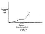
- the printing blanket equipped with a compressible layer which is disclosed in the three prior arts pointed out above, gives rise to the problem that a flat region A in which the compressive stress (MPa) is not in proportion to the smash thickness (mm) is present over a wide range in the compressive stress curve, as apparent from the graph showing the change in the compressive stress relative to the smash thickness (pushing amount) shown in FIG. 7 included in the accompanying drawings.
- a difficulty tends to be brought that the compressive stress is not increased in spite of the increase in the smash thickness, so as to cause the printed surface to become blurred.
- the flat region A in the compressive stress curve is further expanded so as to further promote the defect noted above.
- FIG. 2 of U.S. Patent No. 5,364,683 teaches that the density is substantially linearly increased in increasing the smash thickness in the 5056 type printing blanket equipped with a compressible layer manufactured by a salt leaching method.
- the salt leaching method a mixture of a rubber compound and a soluble salt is vulcanized first, followed by extracting the salt with warm water so as to form a compressible layer.
- it is necessary to dispose of the waste water after extraction of the salt so as to make the method troublesome.
- the particular method is not desirable in view of the environmental damage.
- an open void structure is formed in the compressible layer formed by the salt leaching method, giving rise to the problem that the washing solution tends to remain in the compressible layer when the blanket is washed. The washing solution remaining within the compressible layer swells or hardens the compressible layer so as to lower the compressibility of the compressible layer.
- JP 10 175381 A discloses a compressible printing blanket having a compressive layer provided with closed-cells and open-cells, whereby the ratio of open-cells in the all cells is 10 - 70 vol.%.
- the open-cells are formed by a leaching method.
- US-A-5 934 192 discloses a printing blanket in which an open cell compressible layer and a closed cell compressible layer are provided inside a surface printing layer.
- the open cells are prepared by a leaching method.
- An object of the present invention is to provide a compressible printing blanket in which voids are formed in a compressible layer by using microballoons, the compressible printing blanket being substantially free from the flat region in the compressive stress curve in which the compressive stress is maintained substantially constant regardless of the increase in the smash thickness, and a method of manufacturing the particular compressible printing blanket.
- a compressible printing blanket according to claim 1.
- a method of manufacturing a compressible printing blanket comprising the step of:
- a method of manufacturing a compressible printing blanket comprising the steps of:
- a compressible printing blanket according to claim 1.
- the cross section of the compressible layer denotes an optional cross section of the cross sections obtained when the compressible layer is cut in a thickness direction.
- a reinforcing layer is arranged between the surface rubber layer and the compressible layer.
- void having a foreign shape denotes a void other than a spherical void.
- the foreign-shaped void includes, for example, a void having an elliptical cross section, a void having a vertically oblong cross section, a void having a flattened cross section, and an amorphous void.
- the compressible layer contains spherical voids and foreign-shaped voids meeting the ratio defined in formula (1) given above. If the ratio S 2 of the foreign-shaped voids is smaller than 5, the ratio of the relatively thick void wall to the rubber matrix wall partitioning the adjacent voids is rendered deficient, with the result that it is difficult to overcome the phenomenon that the compressive stress is not increased linearly when the smash thickness is increased. On the other hand, if the ratio S 2 of the foreign-shaped voids exceeds 80, the compressible layer fails to play its inherent role, resulting in a poor restoring capability against compression. It is more desirable for the ratio of S 1 to S 2 to fall within a range of between 20 : 80 and 80 : 20.
- the compressible layer is formed mainly of an oil-resistant rubber matrix.
- the oil-resistant rubber matrix can be obtained by vulcanization.
- printing is performed by using an ink using a non-polar solvent, it is possible to use polar polymers such as acrylonitrile-butadiene rubber (NBR), chloroprene rubber (CR), fluorine-contained rubber (FKM) and polyurethane rubber as the rubber material.
- polar polymers such as acrylonitrile-butadiene rubber (NBR), chloroprene rubber (CR), fluorine-contained rubber (FKM) and polyurethane rubber
- the printing is performed by using an ink using a polar solvent, it is possible to use non-polar polymers such as ethylene-propylene rubber (EPDM), and butyl rubber (IIR) as the rubber material.
- EPDM ethylene-propylene rubber
- IIR butyl rubber
- the rubber mixture it is possible for the rubber mixture to contain an additive, as required, in addition to
- the additives used in the present invention include, for example, a vulcanizing agent, a vulcanization accelerator such as D.M (dibenzothiazole, disulfide) and M (2-mercaptobenzothiazole), an aging preventive, a reinforcing agent, a filler and a plasticizer.
- a vulcanizing agent such as D.M (dibenzothiazole, disulfide) and M (2-mercaptobenzothiazole)
- a vulcanization accelerator such as D.M (dibenzothiazole, disulfide) and M (2-mercaptobenzothiazole
- an aging preventive such as D.M (dibenzothiazole, disulfide) and M (2-mercaptobenzothiazole
- the compressible layer may contain glycols.
- glycols used in the present invention include, for example, such as ethylene glycol, diethylene glycol, and triethylene glycol. It is possible for a single or a plurality of different kinds of glycols to be contained in the compressible layer.
- glycol content of the compressible layer it is desirable for the glycol content of the compressible layer to fall within a range of between 0.1 and 15 parts by weight relative to 100 parts by weight of the raw material rubber. It is more desirable for the glycol content noted above to fall within a range of between 1 and 15 parts by weight relative to 100 parts by weight of the raw material rubber.
- the thickness of the compressible layer it is desirable for the thickness of the compressible layer to fall within a range of between 0.2 and 0.6 mm. If the thickness of the compressible layer is smaller than 0.2 mm, it is difficult to impart a sufficient compressibility to the blanket. On the other hand, if the thickness of the compressible layer exceeds 0.6 mm, the ratio of the compressible layer in the blanket is rendered large, with the result that the balance of the members forming the blanket tends to be impaired. If the balance of the constituting members is collapsed, promoted is the problem that the compressive stress is not increased linearly when the smash thickness (pushing amount) is increased. It is more desirable for the thickness of the compressible layer to fall within a range of between 0.2 and 0.4 mm.
- the adhesive layer contains an oil-resistant rubber matrix as a main component. It is possible to use the rubber material and the additives similar to those described previously in conjunction with the compressible layer.
- voids prefferably formed in the adhesive layer and for the shape of the void to be spherical. It is possible to enhance the compressibility of the blanket while suppressing the phenomenon that the compressive stress is not in proportion to the smash thickness by forming spherical voids in the adhesive layer.
- spherical voids It is desirable for the spherical voids to be provided by microballoons.
- the microballoons should desirably be formed of a thermoplastic resin.
- the thermoplastic resins used for forming the microballoons include, for example, a copolymer between methacrylonitrile and acrylonitrile, homopolymers and copolymers of vinylidene halide, fluorine-containing plastic materials, polyaryl ether ketones, nitrile resins, polyamide imides, polyarylates, polybenzoimidazoles, polycarbonates, thermoplastic polyesters, polyether imides, polyamides, polymethyl pentene, modified polyphenylene oxide, polyphenylene sulfide, polypropylene, and chlorinated polyvinyl chloride.
- the microballoons can be formed by using a single or a plurality of the thermoplastic resins enumerated above. Particularly, it is desirable for the microballoons to contain a copolymer between methacrylonitrile and acrylonitrile.
- microballoons It is desirable for the microballoons to contain a copolymer between methacrylonitrile and acrylonitrile.
- the copolymer has a thermal deformation temperature not lower than 120°C and has a resistance to pressure of 40 kg/cm 2 .
- the microballoons prefferably have an average particle diameter falling within a range of between 1 and 200 ⁇ m. If the average particle diameter is smaller than 1 ⁇ m, the thickness of the wall defining the cell (void) is increased, resulting in failure to obtain a high compressibility. On the other hand, if the average particle diameter of the microballoons exceeds 200 ⁇ m, the thickness of the wall defining the void is rendered excessively small, with the result that the compressibility is rendered excessively large. In other words, the blanket tends to be rendered excessively soft. It is more desirable for the average particle diameter of the microballoons to fall within a range of between 30 ⁇ m and 100 ⁇ m.
- microballoons applied to an expanding treatment and having an average particle diameter falling within a range of between 1 ⁇ m and 200 ⁇ m as the microballoons contained in the unvulcanized compressible layer.
- microballoons not applied to an expanding treatment and having an average particle diameter falling within a range of between 1 ⁇ m and 200 ⁇ m as the microballoons contained in the unvulcanized compressible layer.
- the average particle diameter of the microballoons is measured by the method described below.
- microballoons are collected, disposed on a slide of a microscope and spreaded over the slide such that the microballoon particles are positioned apart from each other.
- the reflex of the microscope is transferred into a computer through a video camera so as to process and analyze the reflex and, thus, to measure the radius of the particles. At least 1,000 microballoons are analyzed so as to obtain an average particle diameter.
- the microballoon content of the adhesive layer it is desirable for the microballoon content of the adhesive layer to fall within a range of between 1 and 4 parts by weight relative to 100 parts by weight of the raw material rubber. If the content of the microballoons is smaller than 1 part by weight, it is difficult to obtain a sufficient effect of improving the compressibility of the blanket. Therefore, it is possible for the compressibility of the blanket to be substantially equal to that of the solid (microballoon content of 0 part by weight). On the other hand, if the microballoon content of the adhesive layer exceeds 4 parts by weight, it is possible for the adhesive layer to play the role of a compressible layer rather than the role of the adhesive layer for bonding the fabric layer. Since the adhesive layer fails to play its original role, deviation among the fabric layers tends to take place so as to bring about the problem such as the printing deviation.
- spherical voids alone to be formed in the adhesive layer. It is also possible for both the spherical voids and voids having a foreign shape to be formed in the adhesive layer. As pointed out previously, foreign-shaped voids denote the voids other than the spherical voids. The foreign-shaped voids are shaped as described previously in conjunction with the compressible layer.
- P 1 : P 2 20 : 80 to 95 : 5
- P 1 denotes the number of spherical voids per unit area in a cross section of the adhesive layer
- P 2 denotes the number of foreign-shaped voids per unit area in a cross section of the adhesive layer.
- the cross section of the adhesive layer denotes an optional cross section among the cross sections obtained when the adhesive layer is cut in a thickness direction.
- the ratio between the spherical voids and the foreign-shaped voids satisfies formula (3) given above, it is possible to suppress more effectively the phenomenon that the compressive stress is rendered substantially constant regardless of the increase in the smash thickness. It is also possible to improve the compressibility of the blanket. It is more desirable for the ratio of P 1 to P 2 to fall within a range of between 20 : 80 and 80 : 20.
- the thickness of the adhesive layer it is desirable for the thickness of the adhesive layer to fall within a range of between 0.03 mm and 0.1 mm. If the thickness of the adhesive layer is smaller than 0.03 mm, the thickness of the adhesive layer tends to become nonuniform, resulting in failure to obtain a uniform adhesive force. On the other hand, if the thickness of the adhesive layer exceeds 0.1 mm, it is possible for the adhesive layer to fail to play its original role. As a result, deviation takes place among the fabric layers so as to bring about the problem such as printing deviation.
- the surface rubber layer prefferably be formed of a vulcanized sheet of a rubber blend. It is possible to use, for example, an acrylonitrile-butadiene rubber as the rubber material contained in the rubber blend.
- the compressible printing blanket of the present invention includes at least two fabric layers. It is desirable for these fabric layers to be made integral by the adhesive layer interposed between the adjacent fabric layers.
- the reinforcing layer prefferably be formed of, for example, a cotton cloth.
- the compressible printing blanket of the present invention is formed by the manufacturing method (A) or the manufacturing method (B) given below.
- a rubber blend containing a rubber material, microballoons, a melting agent of the microballoons, and a solvent. Then, an unvulcanized compressible layer is formed by coating a fabric layer with the rubber blend.
- a microballoon melting agent whose compatibility with the microballoons is not excessively high under room temperature and is increased in the temperature elevation stage such as the rubber vulcanizing step.
- a melting agent includes, for example, glycols. Glycols are particularly effective for microballoons containing a copolymer between methacrylonitrile and acrylonitrile.
- glycols it is desirable to use ethylene glycol, diethylene glycol and triethylene glycol. It is possible to use a single or a plurality of glycols as the melting agent.
- the content of the melting agent of the microballoons in the unvulcanized compressible layer is desirable for the content of the melting agent of the microballoons in the unvulcanized compressible layer to fall within a range of between 0.1 and 15 parts by weight relative to 100 parts by weight of the rubber material. If the microballoon melting agent is added to the unvulcanized compressible layer, the compatibility between the microballoons and the melting agent is increased in the rubber vulcanizing step. As a result, the cells of the microballoons are collapsed by the melting so as to bring about coupling of the cells and, thus, to obtain voids having a foreign shape. It is possible to control the mixing ratio of the foreign-shaped voids by, for example, controlling the addition amount of the melting agent.
- the mixing ratio S 2 of the foreign-shaped voids is rendered smaller than 5.
- the content of the melting agent is higher than 15 parts by weight, the mixing ratio S 2 of the foreign-shaped voids is caused to exceed 80.
- the addition amount of the microballoon melting agent is more desirable for the addition amount of the microballoon melting agent to fall within a range of between 1 and 15 parts by weight.
- the addition amount of the melting agent is excessively large, the compressibility of the compressible layer tends to be increased. It is desirable for the addition amount of the melting agent to fall within a range of between 1 and 3 parts by weight in order to control smoothly the printing surface relative to the smash thickness without increasing the compressibility.
- the microballoon content of the unvulcanized compressible layer is desirable for the microballoon content of the unvulcanized compressible layer to fall within a range of between 5 and 15 parts by weight relative to 100 parts by weight of the rubber material. If the microballoon content is lower than 5 parts by weight, the amount of voids within the compressible layer tends to become insufficient so as to result in failure to obtain a sufficient compressible layer. On the other hand, if the microballoon content is higher than 15 parts by weight, the thickness of the rubber matrix wall partitioning the adjacent voids is rendered thin, resulting in buckling of the void wall by the compression force during use. It follows that it is possible to promote the problem that the compressive stress is not increased linearly in accordance with increase in the smash thickness (pushing amount).
- the average particle diameter of the microballoons contained in the unvulcanized compressible layer is desirable for the average particle diameter of the microballoons contained in the unvulcanized compressible layer to fall within a range of between 1 and 200 ⁇ m. If the average particle diameter is smaller than 1 ⁇ m, the thickness of the wall defining the cell (void) is increased, resulting in failure to obtain a sufficient compressibility. On the other hand, if the average particle diameter exceeds 200 ⁇ m, the wall thickness is decreased so as to render the compressibility excessively large. In other words, it is possible for the blanket to be rendered excessively soft. It is possible to use microballoons applied to an expanding treatment and having an average particle diameter falling within a range of between 1 ⁇ m and 200 ⁇ m as the microballoons added to the unvulcanized compressible layer.
- microballoons not applied to an expanding treatment and having an average particle diameter falling within a range of between 1 ⁇ m and 200 ⁇ m as the microballoons added to the unvulcanized compressible layer. It is more desirable for the average particle diameter of the microballoons to fall within a range of between 30 ⁇ m and 100 ⁇ m. Incidentally, the average particle diameter of the microballoons is measured by the method described previously.
- prepared is a rubber blend containing a rubber material and a solvent as the unvulcanized adhesive layer. It is possible to add microballoons to the unvulcanized adhesive layer. Incidentally, in order to obtain the adhesive layer having the ratio between the spherical voids and the foreign-shaped voids satisfying formula (3) given previously, added are microballoons and a melting agent of the microballoons.
- a blanket precursor including at least two fabric layers, an unvulcanized adhesive layer arranged between adjacent fabric layers, an unvulcanized surface rubber layer, and an unvulcanized compressible layer arranged between at least two fabric layers and the unvulcanized surface rubber layer.
- the blanket precursor thus prepared is vulcanized under temperatures not lower than 120°C, preferably under temperatures falling within a range of between 120°C and 160°C, followed by cooling the vulcanized blanket precursor and subsequently polishing the surface rubber layer so as to obtain a compressible printing blanket of the present invention.
- the vulcanization is performed in a single step so as to make it possible to simplify the manufacturing process. In addition, it is possible to suppress the deterioration of the fabric layers and the reinforcing layer caused by the heating.
- prepared is a rubber blend containing a rubber material, microballoons, a melting agent of the microballoons, and a solvent, followed by coating the fabric layer with the resultant rubber blend so as to form an unvulcanized compressible layer. Then, a reinforcing layer is laminated on the unvulcanized compressible layer so as to obtain a laminate structure. It is possible to use the microballoons and the melting agent of the microballoons similar to those described previously in conjunction with the manufacturing method (A).
- the laminate structure is subjected to a heat treatment at temperatures not lower than 120°C, preferably at temperatures falling within a range of between 120°C and 160°C, so as to vulcanize the unvulcanized compressible layer. It is desirable for the vulcanizing treatment to be performed for 1 to 6 hours.
- a second fabric layer is laminated.
- the number of fabric layers is not limited to two. It is possible for three or more fabric layers to be laminated one upon the other.
- an unvulcanized surface rubber layer is laminated so as to obtain a rubber blanket precursor. It is possible for the unvulcanized adhesive layer to be formed of a rubber blend containing a rubber material and a solvent. It is also possible to add microballoons to the unvulcanized adhesive layer. Incidentally, in order to obtain the adhesive layer containing spherical voids and foreign-shaped voids mixed to satisfy formula (3) described previously, added are microballoons and a melting agent of the microballoons.
- the rubber blanket precursor thus prepared is subjected to a heat treatment under temperatures not lower than 120°C, preferably under temperatures falling within a range of between 120°C and 160°C, so as to vulcanize the layers other than the unvulcanized compressible layer, e.g., to vulcanize the unvulcanized surface rubber layer and the unvulcanized adhesive layer, followed by cooling the rubber blanket precursor and subsequently polishing the surface rubber layer so as to obtain a compressible printing blanket of the present invention.
- the vulcanization is carried out twice.
- the unvulcanized compressible layer is vulcanized and formed, followed by vulcanizing the other layers including the unvulcanized surface rubber layer and the unvulcanized adhesive layer.
- the particular method makes it possible to suppress the influences such as the heat conductivity and the pressure, present in the vulcanizing step of the unvulcanized compressible layer, to the other layers. It follows that it is possible to form the compressible layer with a higher stability.
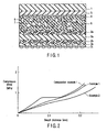
- FIG. 1 schematically shows as an example the construction of the compressible printing blanket according to one embodiment of the present invention.
- the compressible printing blanket of the present invention comprises a surface rubber layer 1 and three fabric layers 2a to 2c.
- Each of the fabric layers 2a to 2c is formed of, for example, a cotton cloth.
- these three fabric layers 2a to 2c are made integral by an adhesive layer 3a interposed between the fabric layers 2a and 2b and another adhesive layer 3b interposed between the fabric layers 2b and 2c.
- the compressible printing blanket also comprises a reinforcing layer 4 and an adhesive layer 5.
- the reinforcing layer 4 which is formed of, for example, a cotton cloth, is laminated on the back surface of the surface rubber layer 1 with the adhesive layer 5 interposed therebetween.
- the compressible printing blanket of the present invention also includes a compressible layer 6, which is interposed between the uppermost layer 2a of the three fabric layers 2a to 2c, i.e., the fabric layer 2a on the side of the surface rubber layer 1, and the reinforcing layer 4.
- the compressible layer 6 contains spherical voids 7 and voids 8 having a foreign shape.
- FIG. 1 shows that the foreign-shaped voids 8 include amorphous voids, elliptical voids, etc. It is desirable for the ratio between the spherical voids 7, i.e., S 1 , and the foreign-shaped voids 8, i.e., S 2 , to fall within a range of between 20 : 80 and 95 : 5. It should be noted that these spherical voids 7 and the foreign-shaped voids 8 are formed by using microballoons.
- the blanket of the particular construction it is possible to suppress the phenomenon that the compressive stress is left substantially constant in spite of the increase in the smash thickness so as to overcome the problem that the printing surface is blurred in spite of the increase of the smash thickness. It follows that it is possible to control the concentration of the printing caused by the smash thickness without fail.
- the particular effect is considered to be derived by the mechanism described below.
- the problem that the compressive stress is not increased linearly in proportion to the smash thickness (pushing amount), i.e., the problem that the compressive stress is not increased in spite of the increase in the smash thickness so as to blur the printing, is rendered prominent if the compressibility of the compressible layer is increased.
- the particular problem is considered to be caused by the buckling of the rubber matrix wall partitioning the adjacent cells (voids) in the compressible layer.
- the thickness of the rubber matrix wall partitioning the adjacent cells is rendered uniform.
- the compressible layer containing the spherical voids and the voids having a foreign shape in a ratio defined by formula (1) as in the present invention it is possible to impart a suitable nonuniformity to the thickness of the rubber matrix partitioning the adjacent voids (cells) so as to make it possible to render nonuniform the deformation behavior of the rubber wall present between the adjacent cells when a smash thickness is applied to the blanket. It follows that it is possible to avoid the phenomenon that the rubber wall in the compressible layer is buckled simultaneously so as to make it possible to narrow the smash thickness region in which the compressive stress does not increase in proportion to the smash thickness. As a result, it is possible to control more accurately the concentration of the printing owing to the smash thickness.
- the problems described below are brought about, if the compressibility of the blanket is increased by (a) softening the rubber matrix of the compressible layer, (b) increasing the porosity of the compressible layer, and (c) increasing the thickness of the compressible layer.
- the compressibility of the blanket is increased by (a) softening the rubber matrix of the compressible layer, (b) increasing the porosity of the compressible layer, and (c) increasing the thickness of the compressible layer.
- it is possible to promote the problem that the compressive stress is not increased linearly when the smash thickness (pushing amount) is increased.
- Sulfur, a vulcanization accelerator M (2-mercaptobenzothiazole), an aging preventive, a reinforcing agent and a plasticizer were added to 100 parts by weight of a medium high acrylonitrile-butadiene rubber (NBR), and the resultant mixture was dissolved in methyl ethyl ketone so as to prepare a rubber paste A.
- NBR medium high acrylonitrile-butadiene rubber
- Rubber paste B was obtained by adding 14 parts by weight of Exbancell 092DE (trade name of microballoons formed of a copolymer between methacrylonitrile and acrylonitrile manufactured by Novel Industries Inc.) and 8 parts by weight of diethylene glycol used as a melting agent to rubber paste A described above. Incidentally, the average particle diameter of the microballoons was 80 ⁇ m.
- an unvulcanized adhesive layer 3a After formation of an unvulcanized adhesive layer 3a by coating the other surface of the cotton cloth 2a with the rubber paste A to a thickness of 0.05 mm, a cotton cloth 2b used as an intermediate fabric layer was pasted to the unvulcanized adhesive layer 3a. Further, after formation of the unvulcanized adhesive layer 3b by coating the surface of the cotton cloth 2b with the rubber paste A to a thickness of 0.05 mm, a cotton cloth 2c used as a lower fabric layer was pasted to the unvulcanized adhesive layer 3b.
- an acrylonitrile-butadiene rubber blended material sheet was laminated as the unvulcanized surface rubber layer 1 on the unvulcanized adhesive layer 5 so as to obtain an unvulcanized compressive rubber blanket (blanket precursor) having a thickness of about 2.1 mm.
- the unvulcanized compressible rubber blanket was wound around a metal drum, followed by heating the unvulcanized compressible rubber blanket at 150°C for 6 hours within a vulcanizing can so as to finish the vulcanization.
- Example 2 Further, the vulcanized compressible rubber blanket was cooled, followed by polishing the surface rubber layer with a sand paper of 240 mesh so as to obtain a compressible blanket constructed as shown in FIG. 1 and having a thickness of 1.9 mm.
- Example 2
- Rubber paste C was obtained by adding 3 parts by weight of microballoons substantially equal to those referred to in Example 1 to the rubber paste A of the composition similar to that referred to in Example 1.
- An unvulcanized compressible rubber blanket having a thickness of about 2.1 mm was prepared as in Example 1, except that used was the rubber paste C in the unvulcanized adhesive layer.
- the unvulcanized compressible rubber blanket was wound around a metal drum, the unvulcanized compressible rubber blanket was heated at 150°C for 6 hours in a vulcanizing can so as to finish the vulcanization.
- the vulcanized compressible rubber blanket was cooled, followed by polishing the surface rubber layer with a sand paper of 240 mesh so as to obtain a compressible blanket constructed as shown in FIG. 1 and having a thickness of 1.9 mm.
- microballoons formed of a copolymer between methacrylonitrile and acrylonitrile is scarcely melted and collapsed under the ordinary vulcanizing temperature, i.e., at 120°C to 160°C, in the case where the melting agent of diethylene glycol is not added or is added in only a small amount.
- 8 parts by weight of the melting agent was contained in the rubber paste B, with the result that it was possible to form the compressible layer 6 while vulcanizing the surface rubber layer 4, etc. under the ordinary vulcanizing temperature, i.e., at 120°C to 160°C. It follows that, in each of Examples 1 and 2, it is possible to suppress the deterioration of the cotton cloth caused by the heat. Also, since a microballoon melting agent was not contained in the adhesive layer for Example 2, the microballoons were not melted in the vulcanizing step so as to obtain an adhesive layer containing spherical microballoons.
- a compressible blanket having a thickness of 1.9 mm was obtained as in Example 1, except that the mixing amount of diethylene glycol in the rubber paste B was set at 0 parts by weight.
- a compressible blanket having a thickness of 1.9 mm was obtained as in Example 2, except that the mixing amount of diethylene glycol in the rubber paste B was set at 0 parts by weight.
- the number of spherical voids and the number of foreign-shaped voids (voids other than the spherical voids) in an optional cross section of the cross sections (surfaces to which the laminate structure is exposed) obtained when the compressible blanket is cut in a thickness direction were measured for the compressible blanket obtained in each of Examples 1, 2 and the Comparative Examples 1, 2 so as to calculate the number S 1 of spherical voids per unit area (1 mm 2 ) and the number S 2 of foreign-shaped voids per unit area (1 mm 2 ), thereby obtaining a ratio between the number S 1 of spherical voids per unit area and the number S 2 of foreign-shaped voids per unit area.
- Table 1 shows the results.
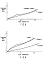
- FIGS. 2 and 3 is a graph showing the compressive stress curve obtained on the basis of the compressive stress thus measured.
- the smash thickness is plotted on the abscissa, with the compressive stress (MPa) plotted on the ordinate.
- the compressive stress is increased substantially linearly when the smash thickness (pushing amount) is increased in the compressible blanket for each of Examples 1 and 2 of the present invention.
- FIG. 2 also shows clearly that a flat region in which the compressive stress is scarcely increased in spite of the increase in the smash thickness is present around the smash thickness of 0.1 mm in the compressible blanket for Comparative Example 1.
- FIG. 3 clearly shows that the compressive stress is increased substantially linearly with increase in the smash thickness in the compressible blanket for Example 2 of the present invention.
- a flat region in which the compressive stress is scarcely increased in spite of the increase in the smash thickness is present in the smash thickness of around 0.1 mm in the compressible blanket for Comparative Example 2.
- the compressible rubber blanket for Example 1 of the present invention was used in an off-set rotary press, with the result that it was possible to control smoothly the printing surface relative to the smash thickness. Also, it was possible to increase the compressibility of the compressible rubber blanket for Example 2, compared with the compressible rubber blanket for Example 1. It should be noted that the high compressibility permits diminishing the amount of change in the compressive stress relative to the smash thickness so as to make it possible to perform easily the fine adjustment of the concentration, particularly, the fine adjustment in the region of low concentration. Examples 3 to 5:
- a compressible blanket constructed as shown in FIG. 1 and having a thickness of 1.9 mm was obtained as in Example 1, except that the mixing amounts of diethylene glycol in the rubber paste B forming the compressible layer were changed as shown in Table 1.
- Example 1 A ratio of the number S 1 of spherical voids per unit area to the number S 2 of foreign-shaped voids per unit area was obtained as in Example 1 with respect to the compressible blanket obtained in each of Examples 3 to 5. Table 1 also shows the results.
- Example 1 The compressive stress was measured as in Example 1 for the compressible blanket obtained in each of Examples 3 to 5 of the present invention, and the compressive stress curves based on the compressive stress thus measured are shown in FIG. 4 .
- a compressible blanket constructed as shown in FIG. 1 and having a thickness of 1.9 mm was obtained as in Example 1, except that the mixing amounts of diethylene glycol in the rubber paste B forming the compressible layer were changed as shown in Table 1.
- Example 1 A ratio of the number S 1 of spherical voids per unit area to the number S 2 of foreign-shaped voids per unit area was obtained as in Example 1 with respect to the compressible blanket obtained in Comparative Examples 3. Table 1 also shows the results.
- the compressible blanket for Comparative Example 3 was poor in the restoring capability after receipt of the compressive stress and was not in the state of performing the desired function of the compressible blanket.
- Table 1 Mixing amount (parts by weight) of diethylene glycol in rubber paste B Spherical voids : foreign-shaped voids S 1 : S 2
- Example 1 8 60:40
- Example 2 8 60:40
- Example 3 0.1 95:5
- Example 4 3
- an unvulcanized adhesive layer 3a was formed by coating the other surface of the cotton cloth 2a with the rubber paste A in a thickness of 0.05 mm, a cotton cloth 2b used as an intermediate fabric layer was pasted to the unvulcanized adhesive layer 3a. Further, after an unvulcanized adhesive layer 3b was formed by coating the surface of the cotton cloth 2b with the rubber paste A in a thickness of 0.05 mm, a cotton cloth 2c used as the lower fabric layer was pasted to the unvulcanized adhesive layer 3b.
- an unvulcanized adhesive layer 5 was formed by coating the surface of the reinforcing layer 4 with the rubber paste A in a thickness of 0.05 mm
- a sheet of an acrylonitrile-butadiene rubber blend was laminated as the unvulcanized surface rubber layer 1 so as to obtain a compressible rubber blanket (blanket precursor), which was partly unvulcanized and had a thickness of about 2.1 mm.
- the vulcanized compressible rubber blanket was cooled, followed by polishing the surface rubber layer with a sand paper of 240 mesh so as to obtain a compressible blanket constructed as shown in FIG. 1 and having a thickness of 1.9 mm.
- Example 6 A cross section of the compressible rubber blanket for Example 6, which was cut in a thickness direction, was observed. It has been found that the thickness of the compressible layer was highly uniform, compared with the compressible rubber blanket obtained in Example 1. Also, a ratio of the number S 1 of the spherical voids per unit area to the number S 2 of the foreign-shaped voids per unit area was determined as in Example 1. The ratio S 1 : S 2 was found to be 60 : 40. Examples 7 and 8:
- a compressible blanket constructed as shown in FIG. 1 and having a thickness of 1.9 mm was obtained as in Example 1, except that the mixing amounts of diethylene glycol in the rubber paste B forming the compressible layer were changed as shown in Table 2.
- Example 2 A ratio of the number S 1 of the spherical voids per unit area to the number S 2 of the foreign-shaped voids per unit area was obtained as in Example 1 with respect to the compressible blanket obtained in each of Examples 7 and 8. Table 2 also shows the results.
- the increase in weight of the compressible blanket, when dipped in an aqueous solution of isopropyl alcohol, is larger in each of Examples 7 and 8 of the present invention than that in Comparative Example 1.
- the large increase in weight in the present invention was caused by the phenomenon that the 5% aqueous solution of isopropyl alcohol was taken into the compressible layer in the compressible blanket for the present invention.
- the dipping experiment supports that open cells (voids) are formed by the collapse of the microcapsules so as to allow the compressible layer to contain both spherical voids and foreign-shaped voids.
- an open cell structure is formed partially in the compressible layer of the compressible blanket for each of Examples 7 and 8, with the result that it is possible to avoid the problem that the washing solution remains within the compressible layer when the compressible blanket is subjected to an automatic washing.
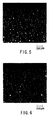
- a cross section, to which the laminate structure is exposed, of the compressible blanket for each of Examples 7 and 8 was observed with a scanning electron microscope. It has been found that both the spherical voids and the foreign-shaped voids are present in the compressible layer, that most of the spherical voids are formed of the voids of the spherical microballoons, that the foreign-shaped voids includes the voids of the microballoons deformed by the melting and the voids in which the partitions provided by the microballoons are not found and pieces of the microballoons collapsed by the melting were found to be present. Further, substantially all the microballoons added to the adhesive layer for Example 2 were found to retain a spherical shape equal to the shape before addition to the adhesive layer.
- FIG. 5 is a scanning electron micrograph (magnification of 45) showing the compressible blanket for Example 7
- FIG. 6 is a scanning electron micrograph (magnification of 45) showing the compressible blanket for Comparative Example 1.
- both the spherical voids and the foreign-shaped voids are present in the compressible layer of the compressible blanket for Example 7, and substantially all the voids are spherical in the compressible layer of the compressible blanket for Comparative Example 1.
- the present invention provides a compressible printing blanket having a diminished smash thickness region in which the compressive stress is not increased linearly with increase in the smash thickness in the compressive stress curve and a method of manufacturing the particular compressible printing blanket.
Landscapes
- Printing Plates And Materials Therefor (AREA)
Claims (27)
- Komprimierbares Drucktuch, welches umfasst:mindestens zwei Stoffschichten (2a, 2b, 2c);eine zwischen benachbarte Stoffschichten (2a, 2b, 2c) gesetzte Haftschicht (3a, 3b);eine Oberflächengummischicht (1); undeine zwischen den mindestens zwei Stoffschichten (2a, 2b, 2c) und der Oberflächengummischicht (1) angeordnete und kugelförmige Leerräume (7) und Leerräume (8) mit einer anderen Form als einer Kugel in einem Verhältnis, das in der nachstehenden Formel (1) festgelegt ist, enthaltende komprimierbare Schicht (6):
 wobei S1 die Zahl der kugelförmigen Leerräume (7) pro Flächeneinheit in einem Querschnitt der komprimierbaren Schicht (6) angibt und S2 die Zahl von Leerräumen (8) mit einer anderen Form als einer Kugel pro Flächeneinheit in einem Querschnitt der komprimierbaren Schicht (6) angibt,dadurch gekennzeichnet, dassdie Leerräume (8), die eine andere Form als eine Kugel aufweisen, mit Hilfe von Mikroballons und einem Schmelzmittel der Mikroballons gebildet sind.
 - Komprimierbares Drucktuch nach Anspruch 1, dadurch gekennzeichnet, dass die komprimierbare Schicht (6) Glykole enthält.
- Komprimierbares Drucktuch nach Anspruch 2, dadurch gekennzeichnet, dass der Anteil der Glykole in der komprimierbaren Schicht (6) in einen Bereich zwischen 0,1 und 15 Gewichtsteile fällt.
- Komprimierbares Drucktuch nach einem der Ansprüche 1 - 3, dadurch gekennzeichnet, dass die Dicke der komprimierbaren Schicht (6) in einen Bereich zwischen 0,2 mm und 0,6 mm fällt.
- Komprimierbares Drucktuch nach einem der Ansprüche 1 - 4, dadurch gekennzeichnet, dass die Dicke der Haftschicht (3a, 3b) in einen Bereich zwischen 0,03 mm und 0,1 mm fällt.
- Komprimierbares Drucktuch nach einem der Ansprüche 1 - 5, dadurch gekennzeichnet, dass die Haftschicht (3a, 3b) Leerräume enthält.
- Komprimierbares Drucktuch nach einem der Ansprüche 1 - 6, dadurch gekennzeichnet, dass die Haftschicht (3a, 3b) Mikroballons enthält.
- Komprimierbares Drucktuch nach einem der Ansprüche 1 - 7, dadurch gekennzeichnet, dass die Haftschicht (3a, 3b) kugelförmige Leerräume und Leerräume mit einer andere Form als einer Kugel enthält, die unter Verwendung von Mikroballons gebildet sind.
- Komprimierbares Drucktuch nach Anspruch 8, dadurch gekennzeichnet, dass das Verhältnis zwischen den kugelförmigen Leerräumen und den Leerräumen mit einer anderen Form als einer Kugel die nachstehende Formel (3) erfüllt:

- Komprimierbares Drucktuch nach einem der Ansprüche 1 - 9, dadurch gekennzeichnet, dass die Haftschicht (3a, 3b) Glykole enthält.
- Verfahren zum Herstellen eines komprimierbaren Drucktuchs nach einem der Ansprüche 1 - 10, welches folgenden Schritt umfasst:Vulkanisieren eines Tuchvorläufers bei Temperaturen nicht unter 120°C, wobei der Tuchvorläufer mindestens zwei Stoffschichten (2a, 2b, 2c), eine nicht vulkanisierte Haftschicht (3a, 3b), die zwischen benachbarte Stoffschichten (2a, 2b, 2c) gesetzt ist, eine nicht vulkanisierte Oberflächengummischicht (1) und eine nicht vulkanisierte, zwischen den mindestens zwei Stoffschichten (2a, 2b, 2c) und der nicht vulkanisierten Oberflächengummischicht (1) angeordnete komprimierbare Schicht (6) umfasst, und wobei die nicht vulkanisierte komprimierbare Schicht (6) Mikroballons und ein Schmelzmittel der Mikroballons enthält.
- Verfahren zum Herstellen eines komprimierbaren Drucktuchs nach Anspruch 11, dadurch gekennzeichnet, dass das Schmelzmittel Glykole enthält.
- Verfahren zum Herstellen eines komprimierbaren Drucktuchs nach Anspruch 11 oder 12, dadurch gekennzeichnet, dass der Anteil des Schmelzmittels in der nicht vulkanisierten komprimierbaren Schicht (6) in einen Bereich zwischen 0,1 und 15 Gewichtsteile fällt.
- Verfahren zum Herstellen eines komprimierbaren Drucktuchs nach Anspruch 13, dadurch gekennzeichnet, dass der Anteil der Mikroballons in der nicht vulkanisierten komprimierbaren Schicht (6) in einen Bereich zwischen 5 und 15 Gewichtsteile fällt.
- Verfahren zum Herstellen eines komprimierbaren Drucktuchs nach einem der Ansprüche 11 - 14, dadurch gekennzeichnet, dass die Mikroballons ein Copolymer zwischen Methacrylnitril und Acrylnitril enthalten.
- Verfahren zum Herstellen eines komprimierbaren Drucktuchs nach einem der Ansprüche 11 - 15, dadurch gekennzeichnet, dass der durchschnittliche Partikeldurchmesser der Mikroballons in einen Bereich zwischen 1 µm und 200 µm fällt.
- Verfahren zum Herstellen eines komprimierbaren Drucktuchs nach einem der Ansprüche 11 - 16, dadurch gekennzeichnet, dass die nicht vulkanisierte Haftschicht (3a) Mikroballons enthält.
- Verfahren zum Herstellen eines komprimierbaren Drucktuchs nach Anspruch 17, dadurch gekennzeichnet, dass die nicht vulkanisierte Haftschicht (3a) ein Schmelzmittel der Mikroballons enthält.
- Verfahren zum Herstellen eines komprimierbaren Drucktuchs nach einem der Ansprüche 1 - 10, welches folgende Schritte umfasst:Durchführen einer Vulkanisierungsbehandlung bei Temperaturen nicht unter 120°C an einer Laminatstruktur, welche eine Stoffschicht (2a, 2b, 2c), eine Verstärkungsschicht (4) und eine nicht vulkanisierte, zwischen die Stoffschicht (2a, 2b, 2c) und die Verstärkungsschicht (4) gesetzte komprimierbare Schicht (6) umfasst, und wobei die nicht vulkanisierte komprimierbare Schicht (6) Mikroballons und ein Schmelzmittel der Mikroballons enthält;Laminieren von mindestens einer neuen Stoffschicht (2b, 2c) auf der Stoffschicht (2a, 2b) der Laminatstruktur, wobei eine nicht vulkanisierte Haftschicht (3a, 3b) zwischen diese Stoffschichten (2a, 2b, 2c) gesetzt ist, und Laminieren einer nicht vulkanisierten Oberflächengummischicht (1) auf der Verstärkungsschicht (4) der Laminatstruktur, wobei eine nicht vulkanisierte Haftgummischicht (5) dazwischen gesetzt ist, um einen Gummituchvorläufer zu erhalten; undVulkanisieren des Gummituchvorläufers bei Temperaturen nicht unter 120°C.
- Verfahren zum Herstellen eines komprimierbaren Drucktuchs nach Anspruch 19, dadurch gekennzeichnet, dass das Schmelzmittel Glykole enthält.
- Verfahren zum Herstellen eines komprimierbaren Drucktuchs nach Anspruch 19 oder 20, dadurch gekennzeichnet, dass der Anteil des Schmelzmittels in der nicht vulkanisierten komprimierbaren Schicht (6) in einen Bereich zwischen 0,1 und 15 Gewichtsteile fällt.
- Verfahren zum Herstellen eines komprimierbaren Drucktuchs nach Anspruch 21, dadurch gekennzeichnet, dass der Anteil der Mikroballons in der nicht vulkanisierten komprimierbaren Schicht (6) in einen Bereich zwischen 5 und 15 Gewichtsteile fällt.
- Verfahren zum Herstellen eines komprimierbaren Drucktuchs nach einem der Ansprüche 19 - 22, dadurch gekennzeichnet, dass die Mikroballons ein Copolymer zwischen Methacrylnitril und Acrylnitril enthalten.
- Verfahren zum Herstellen eines komprimierbaren Drucktuchs nach einem der Ansprüche 19 - 23, dadurch gekennzeichnet, dass der durchschnittliche Partikeldurchmesser der Mikroballons in den Bereich zwischen 1 µm und 200 µm fällt.
- Verfahren zum Herstellen eines komprimierbaren Drucktuchs nach einem der Ansprüche 19 - 24, dadurch gekennzeichnet, dass die nicht vulkanisierte Haftschicht (3a, 3b) Mikroballons enthält.
- Verfahren zum Herstellen eines komprimierbaren Drucktuchs nach Anspruch 25, dadurch gekennzeichnet, dass die nicht vulkanisierte Haftschicht (3a, 3b) ein Schmelzmittel der Mikroballons enthält.
- Komprimierbares Drucktuch nach einem der Ansprüche 1 - 10, dadurch gekennzeichnet, dass die komprimierbare Schicht (6) eine teilweise offene Zellstruktur aufweist.
Applications Claiming Priority (1)
| Application Number | Priority Date | Filing Date | Title |
|---|---|---|---|
| PCT/JP2001/008456 WO2003031196A1 (fr) | 2001-09-27 | 2001-09-27 | Blanchet d'impression compressif et son procede de production |
Publications (3)
| Publication Number | Publication Date |
|---|---|
| EP1431061A1 EP1431061A1 (de) | 2004-06-23 |
| EP1431061A4 EP1431061A4 (de) | 2006-07-19 |
| EP1431061B1 true EP1431061B1 (de) | 2009-04-29 |
Family
ID=11737764
Family Applications (1)
| Application Number | Title | Priority Date | Filing Date |
|---|---|---|---|
| EP01972543A Expired - Lifetime EP1431061B1 (de) | 2001-09-27 | 2001-09-27 | Druckdecke und verfahren zur herstellung derselben |
Country Status (7)
| Country | Link |
|---|---|
| EP (1) | EP1431061B1 (de) |
| JP (1) | JP3845085B2 (de) |
| CN (1) | CN1281421C (de) |
| AR (1) | AR036435A1 (de) |
| DE (1) | DE60138575D1 (de) |
| ES (1) | ES2326260T3 (de) |
| WO (1) | WO2003031196A1 (de) |
Families Citing this family (10)
| Publication number | Priority date | Publication date | Assignee | Title |
|---|---|---|---|---|
| CN1265973C (zh) | 2001-12-05 | 2006-07-26 | 株式会社金阳社 | 压缩性印刷层的加工方法和印刷橡皮布的加工方法 |
| JP4486313B2 (ja) * | 2003-03-31 | 2010-06-23 | 株式会社明治ゴム化成 | 画像転写シート |
| US20070062394A1 (en) * | 2005-09-19 | 2007-03-22 | John Damewood | Thermoset printing blanket |
| JP2007111895A (ja) * | 2005-10-18 | 2007-05-10 | Mitsubishi Paper Mills Ltd | 平版印刷版の印刷方法 |
| JP5250184B2 (ja) * | 2006-01-19 | 2013-07-31 | 株式会社金陽社 | 印刷用ゴムブランケット |
| CN103660670A (zh) * | 2012-09-05 | 2014-03-26 | 上海新星印刷器材有限公司 | 印刷橡皮布表面层的成型方法 |
| CN105283318B (zh) * | 2013-06-12 | 2018-01-23 | 株式会社金阳社 | 柔版印刷用版材 |
| US10647108B2 (en) * | 2018-04-02 | 2020-05-12 | Canon Kabushiki Kaisha | Image recording apparatus |
| CN109265763A (zh) * | 2018-09-05 | 2019-01-25 | 江苏康普印刷科技有限公司 | 用于印刷胶版的微球体发泡层及其制备方法 |
| CN111421976B (zh) * | 2020-04-22 | 2022-05-31 | 上海昊米新材料科技股份有限公司 | 一种油墨转移介质及其制备方法 |
Family Cites Families (5)
| Publication number | Priority date | Publication date | Assignee | Title |
|---|---|---|---|---|
| US3515625A (en) * | 1965-04-20 | 1970-06-02 | Steve Sedlak | Composite flexible material containing a high proportion of filler particles |
| JP3187728B2 (ja) | 1996-12-19 | 2001-07-11 | 住友ゴム工業株式会社 | 印刷用ブランケット |
| US5934192A (en) | 1997-01-29 | 1999-08-10 | Sumitomo Rubber Industries, Ltd. | Printing blanket |
| JP3062502B1 (ja) * | 1998-09-14 | 2000-07-10 | 住友ゴム工業株式会社 | 印刷ブランケット用圧縮性層とその製造方法および印刷ブランケット |
| DE69912907T2 (de) * | 1998-09-14 | 2004-09-02 | Sumitomo Rubber Industries Ltd., Kobe | Komprimierbare Schicht für Drucktücher und Verfahren zu deren Herstellung |
-
2001
- 2001-09-27 DE DE60138575T patent/DE60138575D1/de not_active Expired - Lifetime
- 2001-09-27 ES ES01972543T patent/ES2326260T3/es not_active Expired - Lifetime
- 2001-09-27 JP JP2003534204A patent/JP3845085B2/ja not_active Expired - Fee Related
- 2001-09-27 EP EP01972543A patent/EP1431061B1/de not_active Expired - Lifetime
- 2001-09-27 CN CN 01819985 patent/CN1281421C/zh not_active Expired - Lifetime
- 2001-09-27 WO PCT/JP2001/008456 patent/WO2003031196A1/ja not_active Ceased
-
2002
- 2002-09-06 AR ARP020103366A patent/AR036435A1/es active IP Right Grant
Also Published As
| Publication number | Publication date |
|---|---|
| JPWO2003031196A1 (ja) | 2005-01-20 |
| EP1431061A4 (de) | 2006-07-19 |
| CN1478024A (zh) | 2004-02-25 |
| WO2003031196A1 (fr) | 2003-04-17 |
| EP1431061A1 (de) | 2004-06-23 |
| DE60138575D1 (de) | 2009-06-10 |
| CN1281421C (zh) | 2006-10-25 |
| AR036435A1 (es) | 2004-09-08 |
| ES2326260T3 (es) | 2009-10-06 |
| JP3845085B2 (ja) | 2006-11-15 |
Similar Documents
| Publication | Publication Date | Title |
|---|---|---|
| US7361245B2 (en) | Compressible printing blanket and method of manufacturing a compressible printing blanket | |
| EP1431061B1 (de) | Druckdecke und verfahren zur herstellung derselben | |
| DE69433595T2 (de) | Thermoplastischer harzschaumstoff und verfahren zur herstellung desselben | |
| KR0157584B1 (ko) | 인쇄 블랭킷용 압축성 플라이 | |
| DE68919783T2 (de) | Drucktuch. | |
| JP2010504234A (ja) | 熱可塑性ポリウレタン又は熱可塑性ポリウレタンアロイの層を有する印刷ブランケット又はスリーブ | |
| JPWO2003031196A6 (ja) | 印刷用圧縮性ブランケット及び印刷用圧縮性ブランケットの製造方法 | |
| DE69910636T2 (de) | Aufladerolle mit Widerstandseinstellschicht | |
| EP1470929B1 (de) | Verfahren zur herstellung einer komprimierbaren drucklage und verfahren zur herstellung eines drucktuchs | |
| EP1459904B1 (de) | Gummituch für den offsetdruck | |
| JP2997602B2 (ja) | 圧縮性ゴムブランケット | |
| JP3239115B2 (ja) | 圧縮性ゴムブランケット | |
| JP2000001061A (ja) | 印刷用ブランケット | |
| JP3239114B2 (ja) | 圧縮性ゴムブランケット | |
| JPH0220392A (ja) | 印刷用圧縮性ブランケットの製法およびこれにより製造された印刷用圧縮性ブランケット | |
| JP2000238457A (ja) | 印刷用ブランケット | |
| JP2001047762A (ja) | 印刷ブランケットとその製造方法 | |
| JPS59123642A (ja) | ゴム発泡体の製造方法 | |
| JP2000043444A (ja) | 圧縮性ゴムブランケットの製造方法 | |
| JP2003054152A (ja) | 印刷用ブランケットの製造方法 | |
| JP2003103957A (ja) | オフセット印刷用ブランケット及びその製造方法 |
Legal Events
| Date | Code | Title | Description |
|---|---|---|---|
| PUAI | Public reference made under article 153(3) epc to a published international application that has entered the european phase |
Free format text: ORIGINAL CODE: 0009012 |
|
| 17P | Request for examination filed |
Effective date: 20030516 |
|
| AK | Designated contracting states |
Kind code of ref document: A1 Designated state(s): AT BE CH CY DE DK ES FI FR GB GR IE IT LI LU MC NL PT SE TR |
|
| AX | Request for extension of the european patent |
Extension state: AL LT LV MK RO SI |
|
| A4 | Supplementary search report drawn up and despatched |
Effective date: 20060616 |
|
| RIC1 | Information provided on ipc code assigned before grant |
Ipc: B32B 5/18 20060101ALI20060609BHEP Ipc: B41N 10/04 20060101ALI20060609BHEP Ipc: B41N 10/02 20060101AFI20030423BHEP |
|
| 17Q | First examination report despatched |
Effective date: 20060830 |
|
| GRAP | Despatch of communication of intention to grant a patent |
Free format text: ORIGINAL CODE: EPIDOSNIGR1 |
|
| GRAS | Grant fee paid |
Free format text: ORIGINAL CODE: EPIDOSNIGR3 |
|
| GRAA | (expected) grant |
Free format text: ORIGINAL CODE: 0009210 |
|
| AK | Designated contracting states |
Kind code of ref document: B1 Designated state(s): DE ES FR GB IT |
|
| REG | Reference to a national code |
Ref country code: GB Ref legal event code: FG4D |
|
| REF | Corresponds to: |
Ref document number: 60138575 Country of ref document: DE Date of ref document: 20090610 Kind code of ref document: P |
|
| REG | Reference to a national code |
Ref country code: ES Ref legal event code: FG2A Ref document number: 2326260 Country of ref document: ES Kind code of ref document: T3 |
|
| PLBE | No opposition filed within time limit |
Free format text: ORIGINAL CODE: 0009261 |
|
| STAA | Information on the status of an ep patent application or granted ep patent |
Free format text: STATUS: NO OPPOSITION FILED WITHIN TIME LIMIT |
|
| 26N | No opposition filed |
Effective date: 20100201 |
|
| PG25 | Lapsed in a contracting state [announced via postgrant information from national office to epo] |
Ref country code: IT Free format text: LAPSE BECAUSE OF NON-PAYMENT OF DUE FEES Effective date: 20090927 |
|
| PGRI | Patent reinstated in contracting state [announced from national office to epo] |
Ref country code: IT Effective date: 20110616 |
|
| REG | Reference to a national code |
Ref country code: FR Ref legal event code: PLFP Year of fee payment: 15 |
|
| REG | Reference to a national code |
Ref country code: FR Ref legal event code: PLFP Year of fee payment: 16 |
|
| REG | Reference to a national code |
Ref country code: FR Ref legal event code: PLFP Year of fee payment: 17 |
|
| REG | Reference to a national code |
Ref country code: FR Ref legal event code: PLFP Year of fee payment: 18 |
|
| PGFP | Annual fee paid to national office [announced via postgrant information from national office to epo] |
Ref country code: DE Payment date: 20200929 Year of fee payment: 20 Ref country code: FR Payment date: 20200930 Year of fee payment: 20 Ref country code: GB Payment date: 20200916 Year of fee payment: 20 |
|
| PGFP | Annual fee paid to national office [announced via postgrant information from national office to epo] |
Ref country code: IT Payment date: 20200824 Year of fee payment: 20 |
|
| PGFP | Annual fee paid to national office [announced via postgrant information from national office to epo] |
Ref country code: ES Payment date: 20201007 Year of fee payment: 20 |
|
| REG | Reference to a national code |
Ref country code: DE Ref legal event code: R071 Ref document number: 60138575 Country of ref document: DE |
|
| REG | Reference to a national code |
Ref country code: GB Ref legal event code: PE20 Expiry date: 20210926 |
|
| PG25 | Lapsed in a contracting state [announced via postgrant information from national office to epo] |
Ref country code: GB Free format text: LAPSE BECAUSE OF EXPIRATION OF PROTECTION Effective date: 20210926 |
|
| REG | Reference to a national code |
Ref country code: ES Ref legal event code: FD2A Effective date: 20220104 |
|
| PG25 | Lapsed in a contracting state [announced via postgrant information from national office to epo] |
Ref country code: ES Free format text: LAPSE BECAUSE OF EXPIRATION OF PROTECTION Effective date: 20210928 |