EP1431079B1 - Système pour la transmission d'un signal indicatif de la condition de fonctionnement d'un pneumatique - Google Patents
Système pour la transmission d'un signal indicatif de la condition de fonctionnement d'un pneumatique Download PDFInfo
- Publication number
- EP1431079B1 EP1431079B1 EP20030016456 EP03016456A EP1431079B1 EP 1431079 B1 EP1431079 B1 EP 1431079B1 EP 20030016456 EP20030016456 EP 20030016456 EP 03016456 A EP03016456 A EP 03016456A EP 1431079 B1 EP1431079 B1 EP 1431079B1
- Authority
- EP
- European Patent Office
- Prior art keywords
- tire
- signal
- vehicle
- circuit
- receiver
- Prior art date
- Legal status (The legal status is an assumption and is not a legal conclusion. Google has not performed a legal analysis and makes no representation as to the accuracy of the status listed.)
- Expired - Lifetime
Links
- 230000006870 function Effects 0.000 claims description 16
- 230000005540 biological transmission Effects 0.000 claims description 11
- 230000011664 signaling Effects 0.000 claims description 9
- 238000004804 winding Methods 0.000 claims description 6
- 230000005611 electricity Effects 0.000 claims description 5
- 230000033001 locomotion Effects 0.000 claims description 4
- 230000003213 activating effect Effects 0.000 claims 1
- 238000001914 filtration Methods 0.000 claims 1
- 238000007789 sealing Methods 0.000 description 7
- 238000000034 method Methods 0.000 description 3
- 230000009471 action Effects 0.000 description 1
- 230000004913 activation Effects 0.000 description 1
- 230000008859 change Effects 0.000 description 1
- 238000006243 chemical reaction Methods 0.000 description 1
- 230000003247 decreasing effect Effects 0.000 description 1
- 230000001934 delay Effects 0.000 description 1
- 238000005265 energy consumption Methods 0.000 description 1
- 238000009434 installation Methods 0.000 description 1
- 239000002184 metal Substances 0.000 description 1
- 230000008569 process Effects 0.000 description 1
Images


Classifications
-
- B—PERFORMING OPERATIONS; TRANSPORTING
- B60—VEHICLES IN GENERAL
- B60C—VEHICLE TYRES; TYRE INFLATION; TYRE CHANGING; CONNECTING VALVES TO INFLATABLE ELASTIC BODIES IN GENERAL; DEVICES OR ARRANGEMENTS RELATED TO TYRES
- B60C23/00—Devices for measuring, signalling, controlling, or distributing tyre pressure or temperature, specially adapted for mounting on vehicles; Arrangement of tyre inflating devices on vehicles, e.g. of pumps or of tanks; Tyre cooling arrangements
- B60C23/02—Signalling devices actuated by tyre pressure
- B60C23/04—Signalling devices actuated by tyre pressure mounted on the wheel or tyre
- B60C23/0408—Signalling devices actuated by tyre pressure mounted on the wheel or tyre transmitting the signals by non-mechanical means from the wheel or tyre to a vehicle body mounted receiver
- B60C23/0415—Automatically identifying wheel mounted units, e.g. after replacement or exchange of wheels
- B60C23/0416—Automatically identifying wheel mounted units, e.g. after replacement or exchange of wheels allocating a corresponding wheel position on vehicle, e.g. front/left or rear/right
-
- B—PERFORMING OPERATIONS; TRANSPORTING
- B60—VEHICLES IN GENERAL
- B60C—VEHICLE TYRES; TYRE INFLATION; TYRE CHANGING; CONNECTING VALVES TO INFLATABLE ELASTIC BODIES IN GENERAL; DEVICES OR ARRANGEMENTS RELATED TO TYRES
- B60C23/00—Devices for measuring, signalling, controlling, or distributing tyre pressure or temperature, specially adapted for mounting on vehicles; Arrangement of tyre inflating devices on vehicles, e.g. of pumps or of tanks; Tyre cooling arrangements
- B60C23/02—Signalling devices actuated by tyre pressure
- B60C23/04—Signalling devices actuated by tyre pressure mounted on the wheel or tyre
- B60C23/0491—Constructional details of means for attaching the control device
- B60C23/0496—Valve stem attachments positioned outside of the tyre chamber
Definitions
- the present invention relates to a system capable of transmitting a signal representing the functioning condition of a tire to a receiver founding aboard a vehicle.
- the invention discloses a system capable of transmitting a signal representing the exceeding, by the difference between the internal pressure of the tire and the atmospheric pressure, a pre-established threshold value. Therefore, this signal represents also the radial deformation of the tire. In fact, the radial deformation of the tire, for a given load, is proportional to the difference in pressure.
- sensors in general electronically-controlled, are located outside or, more often, inside the tire, and are connected to apparatuses processing the data and transmitting them to an external receiver.
- the systems usually comprise an apparatus supplied to each tire to measure the pressure, eventually considering also the temperature inside the tire.
- the apparatus is also used for processing the data sensed by the sensors and for transmitting the data to an external receiver.
- This receiver is connected to a processing central unit that in its turn transmits a signal to the display device usually located on the vehicle cluster.
- the transmission of the signal from the apparatus of each tire to the external receiver occurs by means at least one transmitting and one receiving antenna.
- These systems also comprise at least one harness.
- the functioning of said systems requires a considerable quantity of energy.
- the apparatus measuring the pressure and the temperature of each tire is, therefore, feed or with batteries or alternators or dynamo.
- the purpose of the invention is to remove these disadvantages.
- the invention as claimed, solves the problem of creating a s ystem for transmitting a signal indicating the functioning condition of a tire.
- the receiver is located aboard the vehicle.
- the signalling device is fitted with a first member for feeding energy for sending a warning signal.
- the signalling device further comprises a second member for feeding energy for carrying out the processing functions inside the device.
- the apparatus sends a signal indicating the charge condition of the electric generators.
- a first processing function of the apparatus consists in the transmission, at pre-established time periods, of signals indicating the own proper functioning condition.
- every single apparatus uses an own identifying code.
- the apparatus comprises a receiver, which carries out a self-learning function to associate every single apparatus to the tire on which the apparatus is mounted.
- the receiver associates the codes received according to the pre-fixed sequence to the pre-established position of any single wheel and it identifies the loading sequence.
- the signal of right functioning, sent during the first loading, is used by the receiver for self-learning the position of every single tire relating every single installed apparatus. It is, in fact, sufficient to follow a pre-established loading sequence of the mounted devices, the total number of which is equal to the number of wheels of the vehicle, eventually including the spare wheels.
- a pre-established activation sequence is used; the first received code is associated to a first wheel, the second code to a second wheel, etc until the wheel n, being n the total number of wheels to be controlled.
- a movement sensor of the wheel is further provided in the apparatus, said sensor co-operating to prevent the transmission of the signal of the right functioning of the apparatus sent at pre-established time periods when the vehicle is stationary.
- the apparatus is fitted with an autonomous generator of electricity formed by a winding linked to a magnetic field consisting of a magnet fixed on the structure of the vehicle near the wheel.
- the apparatus is fitted with a receiving circuit in order to obtain a bi-directional transmitting system capable of limiting the feeding of energy just when the vehicle is running.
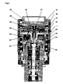
- Fig 1 represents a device (1) for sensing and signalling the state of radial deformation of a loaded tire, mounted on an usual tire inflating valve.
- Said valve substantially consists of a metal tube (2) housing a body (3) fixed, in its turn, inside through a threaded sealing connection (4).
- a self-closing member (5) axially slides inside the threaded connection (4).
- a sealing gasket (6) is held in the closing position by a spring (7).
- the self-closing member (5) is capable of automatically opening, when the pressure, in its part faced towards the outside, that is in the chamber (8), multiplied by the effective surface of the sealing gasket (6) generates on the self-closing member (5) a downwards axial force, is higher than the one due to the pressure existing in its part faced outside, that is in the chamber (9), or inside the tire, multiplied by the effective surface of the sealing gasket (6) added by the force of the spring (7).
- the self-closing member (5) is also open by a mechanical action from outside, by applying a force at its end, in inward direction as shown in Fig 1.
- the device (1) is screwed on the valve replacing the usual protecting cap.
- the device (1) and a good part of its internal member have an axial symmetric shape.
- the device (1) comprises a threaded body (11) consisting of two parts (11a and 11b) welded each other; the threaded body (11) engages the threaded end (10) of the tire inflating valve.
- An external envelope (12) is connected to the threaded body (11).
- a sealing gasket (23) seals the chamber (8) and prevents undesired gas leaks when the device (1) is loaded.
- the loading phase of the device (1) consists in applying an axial push P on the envelope (12) of Fig 1, having module higher than the upwards push due to a spring (24).
- the spring (24) is located between the threaded body (11) and a centring sleeve (25), by means of which the spring (24) pushes upwards the group sensor/amplifier/transducer /actuator (26). Said group is unloaded during a time foregoing the screwing and clamping manoeuvre of the device (1) on the valve. Therefore the group rests on the wall (27) of a box (41) housing the system according to the present invention, wherein the box (41) is found at the opposite end of the threaded body (11) and is sealing stiffly connected to the envelope (12). The sealing is due to a gasket (28) located between the end of the envelope (12) and an abutting founding on the box (41).
- a switch (42) extends from the wall (27) towards the chamber (36) for contacting a plate (39), which is a part of the group (26), when said group (26) is unloaded or during the loading phase. Therefore, in these conditions the switch (42) is in the state opposite to the one that it has when the device is loaded.
- the envelope (12) slides towards the valve (2).
- the envelope (12) causes a push transmitting from the wall (27) to the group sensor/amplifier/transducer/actuator (26), which, in its turn, compresses the spring (24).
- the push of the wall (27) on the group (26) causes the translation of the group (26) towards the upper wall (29) of the threaded body (11) until the abutting.
- the lower end (30) of the housing (31) of the group (26) pushes the self-closing member (5) inwardly the valve (2) against the spring (7) and the push due to the pressure of the gas in the tire on the effective section of the gasket (6), and connects the chamber (9), joined to the inside of the tire, with the chamber (8), delimited by the end (10) of the valve (2), the upper wall (29) of the threaded body (11), the gasket (23) and by a gasket (32), which seals the lower end (30) of the housing (31) of the group (26) with the cylindrical hollow (33) founding in the upper wall (29) of the threaded body (11).
- the gasket (6) is open until the group (26) is displaced towards the threaded body (11), that it is loaded, and automatically closes when the group (26) is far from the threaded body (11).
- Apparatuses are housed inside the group (26) which are capable of carrying out the functions of measuring, amplifying and converting the signal coming from the difference between the pressure of the gas inside the tire and the atmospheric pressure, the apparatuses further indicating the pressure exceeding the pre-established threshold.
- Said apparatuses are technically equivalent to those described in EP-A-0 893 284 ; for this reason, the features of those apparatuses may be more readily understood by referring to this document.
- the circuit of Fig 3 is provided inside the box (41).
- This circuit comprises a generator of electrical energy (B1) (43 in Figs 1, 2), connected to a code generator with output PWM (B3), and to an oscillator (B4) capable of generating the right frequency for transmitting the coded signal.
- a switch (B2) (42 in Figs 1, 2) enables the circuit to transmit the signal when the switch (42) changes over.
- the signal is successively filtered by the filter (B5), emitted through the antenna (B6) and picked up by a receiver (B7) aboard the vehicle.
- the signal generated by the group (26) of Fig 1 is already defined in accordance to the event to be signalled, which is the exceeding of a pre-established threshold of the tire radial deformation, the emission of a simple train of signals without any added information should be sufficient. But a so simple signal is insufficient to identifying the tire in failure, and in the case of proximity of more vehicles fitted with the device, it can be the cause of uncertainty. In fact an adjacent vehicle can receive the signal emitted by the device supplied to the tire of a vehicle. For identifying the tire in failure and decrease the probability of receiving signals from devices not related to own vehicle, a more complex code is necessary, which is typical of the single device.
- the code generator with output PWM (B3) generates this code.
- the choice of the described procedure does not require a fixed correspondence between the code of the device and the single tire. Therefore, it allows, both at the first mounting and in any moment of use of the vehicle, to change the disposition of the devices on the n wheels in any casual way and for any reason without losing the possibility of identification.
- the driver takes care of replacing it with the spare wheel, even if it is not equipped with the device. It is sufficient to unscrew the device of the punctured wheel and mount it on the spare wheel (now mounted in place of the left front wheel) and re-load it: the receiver (B7) recognises the emitted signal as associated to the left front. The same occurs for temporary assembly of snow tires, etc or replacement of the train tires.
- the device is fitted with an inertial sensor capable of identifying the motion or rest condition of the vehicle. In this case, it is possible to act the functions of the devices only when the vehicle is moving.
- the device is fitted with a self-generator of electricity consisting of a winding linked to a magnetic field.
- the rotation of the device during the movement of the wheel induces an electromotive force in the winding, said force being used by the device or by a battery provided in the device.
- Known means are provided to allow a proper charge of the battery.
- the linked magnetic field is generated by a magnet fixed on the structure of the vehicle near the wheel.
- the magnetic field is terrestrial.
Landscapes
- Engineering & Computer Science (AREA)
- Mechanical Engineering (AREA)
- Arrangements For Transmission Of Measured Signals (AREA)
- Measuring Fluid Pressure (AREA)
Claims (17)
- Système pour la transmission d'un signal indicatif de la condition de fonctionnement d'un pneumatique,
le système coopère avec dispositif qui signale la condition de gonflages du pneumatique, et un groupe mobile (26) se trouve dans une première position de chargement lorsque la pression du pneumatique est majeure d'une valeur pré-établie,
le groupe mobile (26) est, au contraire, dans une seconde position de déchargement lorsque la pression du pneumatique est inférieure de la valeur pré-établie et, par conséquent, le pneumatique n'est pas apte à un normal emploie,
le groupe mobile (26) consiste, au moins, d'un capteur, un amplificateur, un transducteur et un actionneur,
le système est caractérisé en ce qu'un interrupteur (42, B2) est prévu qui commute d'une première à une seconde condition, opposée à la première, lorsque le groupe mobile (26) passe de la première position de de chargement à la deuxième de déchargement pour activer un circuit qui envoie un signal d'attention à un récepteur (B7),
un circuit électrique est, en outre, prévu qui comprend un générateur de code (B3), un oscillateur (B4) capable de générer la correcte fréquence pour transmettre le signal codifié, un interrupteur (B2, 42) qui permet au circuit électrique de transmettre le signal lorsque interrupteur (B2,42) commute, un filtre (B5) pour filtrer le signal, une antenne (B6) pour transmettre le signal et un générateur d'énergie électrique (B1) qui alimente tous les composantes du circuit. - Système selon la revendication 1, caractérisé en ce qu'il récepteur (B7) se trouve à bord du véhicule.
- Système selon la revendication 1, caractérisé en ce que le dispositif de signalisation est pourvu d'un second générateur d'énergie électrique pour envoyer un signal d'attention.
- Système selon la revendication 1, caractérisé en ce que le dispositif de signalisation comprend, en outre, un troisième générateur d'énergie électrique pour réaliser les fonctions d'élaboration dans le dispositif.
- Système selon la revendication 1, caractérisé en ce que l'appareil qui transmet un signal d'alarme capté du récepteur (B7) transmet un signal qui indique l'état de chargement des générateurs électriques.
- Système selon la revendication 1, caractérisé en ce qu'une première fonction d'élaboration du circuit consiste en la transmission, à des périodes de temps pré-établie, de signaux qui indiquent le correct état de fonctionnement du circuit.
- Système selon la revendication 1, caractérisé en ce que l'interrupteur (42, B2) permet au circuit de transmettre le signal lorsque le groupe (26) commute l'interrupteur (42, B2).
- Système selon la revendication 7 caractérisé en ce que a transmission du signal qui indique le correct état de fonctionnement du circuit se produit à des pré-établies périodes de temps;
pour épargner de l'énergie, la transmission n'est pas permise lorsque le groupe (26) passe de la première position de déchargement à la seconde position de chargement et commute l'interrupteur (42, B2) de la première à la seconde condition, opposée à la première condition. - Système selon la revendication 1, caractérisé en ce que chaque circuit emploie son code d'identification pour identifier le pneumatique en avarie et limiter la probabilité de recevoir les signaux de dispositifs hors du véhicule.
- Système selon la revendication 1, caractérisé en ce que le système comprend le récepteur (B7);
le récepteur (B7) réalise une fonction d'auto apprentissage pour associer chaque dispositif au pneumatique sur lequel le dispositif est monté; à cette raison le récepteur (B7) associe les codes reçus selon une séquence préfixée à la position pré-établie de toutes les roues et identifie la séquence de montage. - Système selon la revendication 1, caractérisé en ce qu'un signal envoyé pendant le premier montage de chaque dispositif, par exemple le signal de fonctionnement correct, indique au récepteur (B7) la position de chaque pneumatique relatif à chaque dispositif installé ;
pour cette raison, il est suffisant suivre une séquence de montage préfixée pendant le montage du dispositif, dont le nombre total est égal au nombre de roues du véhicule, éventuellement comprise la roue d'escorte ;
le premier code reçu est associé à la première roue; le second code à la seconde roue, etc. jusqu'à le énième roue, en étant n le nombre total de roues à contrôler. - Système selon la revendication 1, caractérisé en ce qu'un capteur du mouvement de la roue est, en outre, prévu dans le dispositif pour épargner de l'énergie,
le capteur agit pour empêcher la transmission du signal du correct fonctionnement du dispositif, envoyé à des pré-établis périodes de temps, lorsque le véhicule est arrêté. - Système selon la revendication 1, caractérisé en ce que le dispositif est pourvu d'un générateur autonome d'électricité formé d'un enroulement concaténé à un champ magnétique.
- Système selon la revendication 1, caractérisé en ce que le dispositif est doué d'un générateur autonome d'électricité formé d'un enroulement concaténé à un champ magnétique engendré d'un aimant fixé à la structure du véhicule prochain à la roue.
- Système selon la revendication 1, caractérisé en ce que l'interrupteur (42, B2) habilite le circuit à transmettre le signal lorsque le groupe (26) commute l'interrupteur (42, B2).
- Système selon la revendication 1, caractérisé en ce que chaque dispositif emploie son code d'identification pour identifier le pneumatique en avarie et limiter la probabilité de recevoir des signaux de dispositifs hors du véhicule.
- Système selon la revendication 1, caractérisé en ce que le circuit est pourvu d'un circuit récepteur pour obtenir un système de transmission bidirectionnel capable de limiter l'alimentation d'énergie à la période où le véhicule est en fonction.
Applications Claiming Priority (2)
| Application Number | Priority Date | Filing Date | Title |
|---|---|---|---|
| ITBO20020789 ITBO20020789A1 (it) | 2002-12-16 | 2002-12-16 | Sistema di trasmissione di un segnale indicante lo |
| ITBO20020789 | 2002-12-16 |
Publications (2)
| Publication Number | Publication Date |
|---|---|
| EP1431079A1 EP1431079A1 (fr) | 2004-06-23 |
| EP1431079B1 true EP1431079B1 (fr) | 2007-11-21 |
Family
ID=32375521
Family Applications (1)
| Application Number | Title | Priority Date | Filing Date |
|---|---|---|---|
| EP20030016456 Expired - Lifetime EP1431079B1 (fr) | 2002-12-16 | 2003-07-22 | Système pour la transmission d'un signal indicatif de la condition de fonctionnement d'un pneumatique |
Country Status (3)
| Country | Link |
|---|---|
| EP (1) | EP1431079B1 (fr) |
| DE (1) | DE60317619T2 (fr) |
| IT (1) | ITBO20020789A1 (fr) |
Families Citing this family (1)
| Publication number | Priority date | Publication date | Assignee | Title |
|---|---|---|---|---|
| US8714002B2 (en) | 2011-01-18 | 2014-05-06 | Barbalab S.R.L. | Device for monitoring the state of radial deformation of a tyre |
Family Cites Families (5)
| Publication number | Priority date | Publication date | Assignee | Title |
|---|---|---|---|---|
| DE3930480A1 (de) * | 1989-09-12 | 1991-03-14 | Rainer Achterholt | Eine ein druckabnahmesignal erzeugende ventilkappe fuer einen luftreifen |
| US5513524A (en) * | 1994-08-08 | 1996-05-07 | Rosenfeld; Alan I. | System for monitoring air pressure in a spare tire |
| US5604481A (en) * | 1995-03-08 | 1997-02-18 | Bai Chj Industrial Co., Ltd. | Tire pressure detector |
| PT893284E (pt) * | 1998-05-28 | 2001-12-28 | Giovanni Barbanti | Dispositivo capaz de sinalizar a condicao de enchimento em pneumaticos |
| EP0979743A1 (fr) * | 1998-08-10 | 2000-02-16 | Huang, Tien-Tsai | Manomètre avec interrupteur d'épargne d'énergie pour un générateur de signaux, actionné par la pression d'un fluide |
-
2002
- 2002-12-16 IT ITBO20020789 patent/ITBO20020789A1/it unknown
-
2003
- 2003-07-22 EP EP20030016456 patent/EP1431079B1/fr not_active Expired - Lifetime
- 2003-07-22 DE DE2003617619 patent/DE60317619T2/de not_active Expired - Fee Related
Also Published As
| Publication number | Publication date |
|---|---|
| EP1431079A1 (fr) | 2004-06-23 |
| DE60317619D1 (de) | 2008-01-03 |
| DE60317619T2 (de) | 2009-01-29 |
| ITBO20020789A1 (it) | 2004-06-17 |
Similar Documents
| Publication | Publication Date | Title |
|---|---|---|
| US5235850A (en) | Arrangement of monitoring the operating state of vehicle pneumatic tires mounted on wheel rims | |
| US4160234A (en) | Abnormal tire condition sensing system | |
| US5285189A (en) | Abnormal tire condition warning system | |
| JP2756863B2 (ja) | 圧力降下信号発生用の弁キャップ | |
| US5987980A (en) | In situ tire valve assembly employing short valve element as antenna | |
| US7341321B2 (en) | Rotation detecting device and anti-skid braking system using the same | |
| US7088226B2 (en) | Method and apparatus for a remote tire pressure monitoring system | |
| CA2214700C (fr) | Appareil a capteurs et transpondeur servant a detecter et a transmettre des donnees parametriques de pneus de vehicules | |
| JP4947934B2 (ja) | 多段式蓄積装置を備えた圧電式電源からの電力変換 | |
| US7701326B2 (en) | Tire information transmitter and tire information acquisition system using the transmitter | |
| EP0587306B1 (fr) | Dispositif d'égalisation et d'indication de la pression de gonflage pour pneumatiques jumelles | |
| JPH07507513A (ja) | 車両用空気入りタイヤの空気圧監視装置 | |
| KR20050086739A (ko) | 타이어 데이터 감지 시스템 | |
| JP4914440B2 (ja) | 圧電装置からのパルスの誘導結合 | |
| US7532957B2 (en) | Method and apparatus for controlling the operation of wheel electronics associated with a vehicle wheel | |
| US20050146424A1 (en) | System for transmitting a signal indicating the functioning condition of a tire | |
| US7205885B2 (en) | Tire sensor communication system | |
| EP1431079A1 (fr) | Système pour la transmission d'un signal indicatif de la condition de fonctionnement d'un pneumatique | |
| EP1384605B1 (fr) | Appareil de surveillance de condition de pneumatique | |
| US7560905B2 (en) | Vehicle steering wheel power switch apparatus and method | |
| GB2171233A (en) | Monitoring tyre inflation | |
| EP0864450A1 (fr) | Arrangement d'un générateur de courant intégré à un palier | |
| JP2005301549A (ja) | 車輪状態監視システム | |
| AU728312B2 (en) | Tyre pressure monitoring transponder mounted on a tyre valve | |
| CA2523809C (fr) | Methode et appareil pour systeme de controle a distance de la pression des pneus |
Legal Events
| Date | Code | Title | Description |
|---|---|---|---|
| PUAI | Public reference made under article 153(3) epc to a published international application that has entered the european phase |
Free format text: ORIGINAL CODE: 0009012 |
|
| AK | Designated contracting states |
Kind code of ref document: A1 Designated state(s): AT BE BG CH CY CZ DE DK EE ES FI FR GB GR HU IE IT LI LU MC NL PT RO SE SI SK TR |
|
| AX | Request for extension of the european patent |
Extension state: AL LT LV MK |
|
| AKX | Designation fees paid | ||
| REG | Reference to a national code |
Ref country code: DE Ref legal event code: 8566 |
|
| 17P | Request for examination filed |
Effective date: 20041208 |
|
| RBV | Designated contracting states (corrected) |
Designated state(s): AT BE BG CH CY CZ DE DK EE ES FI FR GB GR HU IE IT LI LU MC NL PT RO SE SI SK TR |
|
| R17P | Request for examination filed (corrected) |
Effective date: 20041208 |
|
| 17Q | First examination report despatched |
Effective date: 20061124 |
|
| GRAP | Despatch of communication of intention to grant a patent |
Free format text: ORIGINAL CODE: EPIDOSNIGR1 |
|
| GRAS | Grant fee paid |
Free format text: ORIGINAL CODE: EPIDOSNIGR3 |
|
| GRAA | (expected) grant |
Free format text: ORIGINAL CODE: 0009210 |
|
| AK | Designated contracting states |
Kind code of ref document: B1 Designated state(s): AT BE BG CH CY CZ DE DK EE ES FI FR GB GR HU IE IT LI LU MC NL PT RO SE SI SK TR |
|
| REG | Reference to a national code |
Ref country code: GB Ref legal event code: FG4D |
|
| REG | Reference to a national code |
Ref country code: IE Ref legal event code: FG4D |
|
| REG | Reference to a national code |
Ref country code: CH Ref legal event code: EP |
|
| REF | Corresponds to: |
Ref document number: 60317619 Country of ref document: DE Date of ref document: 20080103 Kind code of ref document: P |
|
| PG25 | Lapsed in a contracting state [announced via postgrant information from national office to epo] |
Ref country code: NL Free format text: LAPSE BECAUSE OF FAILURE TO SUBMIT A TRANSLATION OF THE DESCRIPTION OR TO PAY THE FEE WITHIN THE PRESCRIBED TIME-LIMIT Effective date: 20071121 Ref country code: SE Free format text: LAPSE BECAUSE OF FAILURE TO SUBMIT A TRANSLATION OF THE DESCRIPTION OR TO PAY THE FEE WITHIN THE PRESCRIBED TIME-LIMIT Effective date: 20080221 Ref country code: CH Free format text: LAPSE BECAUSE OF FAILURE TO SUBMIT A TRANSLATION OF THE DESCRIPTION OR TO PAY THE FEE WITHIN THE PRESCRIBED TIME-LIMIT Effective date: 20071121 Ref country code: LI Free format text: LAPSE BECAUSE OF FAILURE TO SUBMIT A TRANSLATION OF THE DESCRIPTION OR TO PAY THE FEE WITHIN THE PRESCRIBED TIME-LIMIT Effective date: 20071121 Ref country code: ES Free format text: LAPSE BECAUSE OF FAILURE TO SUBMIT A TRANSLATION OF THE DESCRIPTION OR TO PAY THE FEE WITHIN THE PRESCRIBED TIME-LIMIT Effective date: 20080304 |
|
| NLV1 | Nl: lapsed or annulled due to failure to fulfill the requirements of art. 29p and 29m of the patents act | ||
| PG25 | Lapsed in a contracting state [announced via postgrant information from national office to epo] |
Ref country code: BG Free format text: LAPSE BECAUSE OF FAILURE TO SUBMIT A TRANSLATION OF THE DESCRIPTION OR TO PAY THE FEE WITHIN THE PRESCRIBED TIME-LIMIT Effective date: 20080221 Ref country code: FI Free format text: LAPSE BECAUSE OF FAILURE TO SUBMIT A TRANSLATION OF THE DESCRIPTION OR TO PAY THE FEE WITHIN THE PRESCRIBED TIME-LIMIT Effective date: 20071121 Ref country code: SI Free format text: LAPSE BECAUSE OF FAILURE TO SUBMIT A TRANSLATION OF THE DESCRIPTION OR TO PAY THE FEE WITHIN THE PRESCRIBED TIME-LIMIT Effective date: 20071121 |
|
| REG | Reference to a national code |
Ref country code: CH Ref legal event code: PL |
|
| PG25 | Lapsed in a contracting state [announced via postgrant information from national office to epo] |
Ref country code: AT Free format text: LAPSE BECAUSE OF FAILURE TO SUBMIT A TRANSLATION OF THE DESCRIPTION OR TO PAY THE FEE WITHIN THE PRESCRIBED TIME-LIMIT Effective date: 20071121 |
|
| PG25 | Lapsed in a contracting state [announced via postgrant information from national office to epo] |
Ref country code: CZ Free format text: LAPSE BECAUSE OF FAILURE TO SUBMIT A TRANSLATION OF THE DESCRIPTION OR TO PAY THE FEE WITHIN THE PRESCRIBED TIME-LIMIT Effective date: 20071121 Ref country code: DK Free format text: LAPSE BECAUSE OF FAILURE TO SUBMIT A TRANSLATION OF THE DESCRIPTION OR TO PAY THE FEE WITHIN THE PRESCRIBED TIME-LIMIT Effective date: 20071121 |
|
| PG25 | Lapsed in a contracting state [announced via postgrant information from national office to epo] |
Ref country code: BE Free format text: LAPSE BECAUSE OF FAILURE TO SUBMIT A TRANSLATION OF THE DESCRIPTION OR TO PAY THE FEE WITHIN THE PRESCRIBED TIME-LIMIT Effective date: 20071121 Ref country code: RO Free format text: LAPSE BECAUSE OF FAILURE TO SUBMIT A TRANSLATION OF THE DESCRIPTION OR TO PAY THE FEE WITHIN THE PRESCRIBED TIME-LIMIT Effective date: 20071121 Ref country code: SK Free format text: LAPSE BECAUSE OF FAILURE TO SUBMIT A TRANSLATION OF THE DESCRIPTION OR TO PAY THE FEE WITHIN THE PRESCRIBED TIME-LIMIT Effective date: 20071121 |
|
| PLBE | No opposition filed within time limit |
Free format text: ORIGINAL CODE: 0009261 |
|
| STAA | Information on the status of an ep patent application or granted ep patent |
Free format text: STATUS: NO OPPOSITION FILED WITHIN TIME LIMIT |
|
| PG25 | Lapsed in a contracting state [announced via postgrant information from national office to epo] |
Ref country code: PT Free format text: LAPSE BECAUSE OF FAILURE TO SUBMIT A TRANSLATION OF THE DESCRIPTION OR TO PAY THE FEE WITHIN THE PRESCRIBED TIME-LIMIT Effective date: 20080421 |
|
| 26N | No opposition filed |
Effective date: 20080822 |
|
| PG25 | Lapsed in a contracting state [announced via postgrant information from national office to epo] |
Ref country code: FR Free format text: LAPSE BECAUSE OF FAILURE TO SUBMIT A TRANSLATION OF THE DESCRIPTION OR TO PAY THE FEE WITHIN THE PRESCRIBED TIME-LIMIT Effective date: 20080905 |
|
| PGFP | Annual fee paid to national office [announced via postgrant information from national office to epo] |
Ref country code: DE Payment date: 20080728 Year of fee payment: 6 |
|
| PGFP | Annual fee paid to national office [announced via postgrant information from national office to epo] |
Ref country code: IE Payment date: 20080718 Year of fee payment: 6 |
|
| PGFP | Annual fee paid to national office [announced via postgrant information from national office to epo] |
Ref country code: GB Payment date: 20080602 Year of fee payment: 6 |
|
| PG25 | Lapsed in a contracting state [announced via postgrant information from national office to epo] |
Ref country code: GR Free format text: LAPSE BECAUSE OF FAILURE TO SUBMIT A TRANSLATION OF THE DESCRIPTION OR TO PAY THE FEE WITHIN THE PRESCRIBED TIME-LIMIT Effective date: 20080222 |
|
| PG25 | Lapsed in a contracting state [announced via postgrant information from national office to epo] |
Ref country code: MC Free format text: LAPSE BECAUSE OF NON-PAYMENT OF DUE FEES Effective date: 20080731 |
|
| PG25 | Lapsed in a contracting state [announced via postgrant information from national office to epo] |
Ref country code: EE Free format text: LAPSE BECAUSE OF FAILURE TO SUBMIT A TRANSLATION OF THE DESCRIPTION OR TO PAY THE FEE WITHIN THE PRESCRIBED TIME-LIMIT Effective date: 20071121 |
|
| PG25 | Lapsed in a contracting state [announced via postgrant information from national office to epo] |
Ref country code: CY Free format text: LAPSE BECAUSE OF FAILURE TO SUBMIT A TRANSLATION OF THE DESCRIPTION OR TO PAY THE FEE WITHIN THE PRESCRIBED TIME-LIMIT Effective date: 20071121 |
|
| GBPC | Gb: european patent ceased through non-payment of renewal fee |
Effective date: 20090722 |
|
| PG25 | Lapsed in a contracting state [announced via postgrant information from national office to epo] |
Ref country code: GB Free format text: LAPSE BECAUSE OF NON-PAYMENT OF DUE FEES Effective date: 20090722 |
|
| PG25 | Lapsed in a contracting state [announced via postgrant information from national office to epo] |
Ref country code: DE Free format text: LAPSE BECAUSE OF NON-PAYMENT OF DUE FEES Effective date: 20100202 |
|
| PG25 | Lapsed in a contracting state [announced via postgrant information from national office to epo] |
Ref country code: HU Free format text: LAPSE BECAUSE OF FAILURE TO SUBMIT A TRANSLATION OF THE DESCRIPTION OR TO PAY THE FEE WITHIN THE PRESCRIBED TIME-LIMIT Effective date: 20080522 Ref country code: LU Free format text: LAPSE BECAUSE OF NON-PAYMENT OF DUE FEES Effective date: 20080722 Ref country code: IE Free format text: LAPSE BECAUSE OF NON-PAYMENT OF DUE FEES Effective date: 20090722 |
|
| PG25 | Lapsed in a contracting state [announced via postgrant information from national office to epo] |
Ref country code: TR Free format text: LAPSE BECAUSE OF FAILURE TO SUBMIT A TRANSLATION OF THE DESCRIPTION OR TO PAY THE FEE WITHIN THE PRESCRIBED TIME-LIMIT Effective date: 20071121 |
|
| PG25 | Lapsed in a contracting state [announced via postgrant information from national office to epo] |
Ref country code: IT Free format text: LAPSE BECAUSE OF NON-PAYMENT OF DUE FEES Effective date: 20080731 |