EP1431147B1 - Pedalier de frein - Google Patents
Pedalier de frein Download PDFInfo
- Publication number
- EP1431147B1 EP1431147B1 EP03028929A EP03028929A EP1431147B1 EP 1431147 B1 EP1431147 B1 EP 1431147B1 EP 03028929 A EP03028929 A EP 03028929A EP 03028929 A EP03028929 A EP 03028929A EP 1431147 B1 EP1431147 B1 EP 1431147B1
- Authority
- EP
- European Patent Office
- Prior art keywords
- pedal
- support
- brake pedal
- brake
- bellows
- Prior art date
- Legal status (The legal status is an assumption and is not a legal conclusion. Google has not performed a legal analysis and makes no representation as to the accuracy of the status listed.)
- Expired - Lifetime
Links
- 238000006073 displacement reaction Methods 0.000 claims description 3
- 230000035939 shock Effects 0.000 description 7
- 230000006835 compression Effects 0.000 description 5
- 238000007906 compression Methods 0.000 description 5
- 230000000694 effects Effects 0.000 description 5
- 239000006260 foam Substances 0.000 description 5
- 239000006096 absorbing agent Substances 0.000 description 3
- 230000000994 depressogenic effect Effects 0.000 description 2
- 230000000295 complement effect Effects 0.000 description 1
- 239000002131 composite material Substances 0.000 description 1
- 238000013016 damping Methods 0.000 description 1
- 239000000428 dust Substances 0.000 description 1
- 239000012530 fluid Substances 0.000 description 1
- 230000012010 growth Effects 0.000 description 1
- 230000008520 organization Effects 0.000 description 1
- 239000002245 particle Substances 0.000 description 1
- 230000011664 signaling Effects 0.000 description 1
- 125000006850 spacer group Chemical group 0.000 description 1
Images

Classifications
-
- G—PHYSICS
- G05—CONTROLLING; REGULATING
- G05G—CONTROL DEVICES OR SYSTEMS INSOFAR AS CHARACTERISED BY MECHANICAL FEATURES ONLY
- G05G1/00—Controlling members, e.g. knobs or handles; Assemblies or arrangements thereof; Indicating position of controlling members
- G05G1/30—Controlling members actuated by foot
-
- B—PERFORMING OPERATIONS; TRANSPORTING
- B60—VEHICLES IN GENERAL
- B60T—VEHICLE BRAKE CONTROL SYSTEMS OR PARTS THEREOF; BRAKE CONTROL SYSTEMS OR PARTS THEREOF, IN GENERAL; ARRANGEMENT OF BRAKING ELEMENTS ON VEHICLES IN GENERAL; PORTABLE DEVICES FOR PREVENTING UNWANTED MOVEMENT OF VEHICLES; VEHICLE MODIFICATIONS TO FACILITATE COOLING OF BRAKES
- B60T7/00—Brake-action initiating means
- B60T7/02—Brake-action initiating means for personal initiation
- B60T7/04—Brake-action initiating means for personal initiation foot actuated
- B60T7/06—Disposition of pedal
-
- G—PHYSICS
- G05—CONTROLLING; REGULATING
- G05G—CONTROL DEVICES OR SYSTEMS INSOFAR AS CHARACTERISED BY MECHANICAL FEATURES ONLY
- G05G1/00—Controlling members, e.g. knobs or handles; Assemblies or arrangements thereof; Indicating position of controlling members
- G05G1/30—Controlling members actuated by foot
- G05G1/46—Means, e.g. links, for connecting the pedal to the controlled unit
-
- G—PHYSICS
- G05—CONTROLLING; REGULATING
- G05G—CONTROL DEVICES OR SYSTEMS INSOFAR AS CHARACTERISED BY MECHANICAL FEATURES ONLY
- G05G25/00—Other details or appurtenances of control mechanisms, e.g. supporting intermediate members elastically
- G05G25/02—Inhibiting the generation or transmission of noise
Definitions
- the present invention relates to an improved brake pedal which makes it possible in particular to avoid pedal returns that are too abrupt during a sudden release.
- the object of the present invention is to solve these problems.
- This goal is reached by an elastic damper interposed between a support of the pedal and a push rod of a brake pedal of this pedal.
- the shock absorber then has the effect that at the end of the race the movement of the pedal is idle avoiding the shock cited above.
- this damper acts on a mobile equipment driven by the pedal, and which itself operates a limit switch normally intended to turn on or off brake signaling lights. By doing so we can limit damping at the last part of the pedal stroke and get that the size of the shock fits naturally in the available space.
- the subject of the invention is therefore a brake pedal comprising a support, a pedal articulated on this support, and a push rod for operate a braking equipment, an elastic shock absorber, mounted between the pedal and the support, Said damper being formed by a bellows, characterized in that the bellows comprises a set of hollow truncated conical rubber trunks, nested within each other along their truncated cone axis, and interconnected by crowns.
- Figure 1 shows a pedal 1 brake.
- the pedal 1 has a support 2.
- Support 2 is normally fixed and is attached by means not shown in an apron 3, shown figuratively, separating a Engine compartment 4 of the vehicle 5 of this vehicle.
- the pedal has a pedal 6 articulated by an axis 7 on the support 2.
- the pedal also includes a push rod 8, also represented figuratively, coming to actuate a braking equipment 9.
- the braking equipment 9 is an equipment comprising a hydraulic pump implemented by an electric motor and having a reserve cartridge.
- the braking equipment 9 includes a simulator.
- the braking equipment 9 could have a conventional master cylinder, possibly assisted by a pneumatic braking assistance device.
- this pedal is as follows. At one end 10 of the pedal 6, a force 11 is exerted by the foot of a driver on a skate attached to this pedal 6. The direction of the force 11 forces the pedal 6 to turn around the axis 7 in a direction 12. In doing so, the rod of thrust 8 articulated on the pedal 6 by an axis 13 undergone a movement according to a direction 14.
- a fixed lug 18 secured to the support 2 carries a limit switch 19 actuated by a mobile unit 20, itself driven by the pedal 6 relative to the leg 18.
- An electrical signal delivered by this switch 19 and corresponding to the tripping of braking, is transmitted to the vehicle's traffic lights.
- a damper 21 pedal return takes advantage of the presence of this end switch 19 and this mobile unit 20 to insert at the location of this mobile unit a damper 21 pedal return.
- the damper 21 thus has the effect of preferably in fine, slow down the rise of the pedal 6, which is otherwise driven by the spring 15 and the replica of the equipment 9.
- the damper 21 of the return of the pedal 6 does not produced only during the last 20 percent of the race in return for this pedal. However, it is possible to is exercised gradually over the entire travel back pedal.
- the damper 21 of the invention is interposed between the pedal 6 and the support 2.
- the damper 21 is linked at one end to one side of the moving equipment 20.
- the support 2 is connected by the lug 18 at another end of the damper 21.
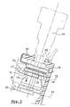
- FIG. 2 shows, in a composite way, two states of the damper 21. While a tab 22 rigidly connected to the pedal 6 is in low position 23, a bellows 24 serving as a damper 21 is in a relaxed position.
- the moving equipment 20 has been reassembled, driven by the tab 22, and compressed the bellows 24 of so that the latter occupies, overall, a position closer to the limit switch 19 than position 23.
- the bellows is compressed and therefore, at the time of braking, exerts a complementary braking assistance effort.
- the position 23 when this position is extreme, and so as to avoid a floating of the damper 24 that continues to remain in slight compression, which facilitates the holding.
- the damper 21 comprises preferably two washers 26 and 27 respectively close and far from the limit switch 19.
- the washer 27 is shown in two positions the position 27 and a position 28, when the pedal is requested for braking.
- the washer 27 bears against the leg 22. In a variant, it is in solidarity.
- the washer 26 is always supported, in particular by through a box 29, against the leg 18. So in the end, the washer 26 is fixed relative to the support 2.
- the washer 27 is attached to one end 30 of the mobile assembly 20. It is also supported by example via a spacer 31 with the tab 22 which is brought by the pedal 6.
- the washer 27 (or 28) is thus led by the 22. It therefore takes support on the push rod.
- Figures 3a and 3b show achievements of a damper.
- bellows typically by a bellows like that of Figure 3b, in which the envelope of the bellows has a profile comprising a set of curvilinear sinusoidal meander.
- a relaxed position shown in solid line
- a position towards compression shown in dotted lines on has found that the structure in regular meanders, typically of type sinusoidal, could undergo deflections leading notably to the moment of the total compression some internal edges of the bellows to this move a gap 31 in the direction of the axis of the bellows.
- FIG. 3a In contrast, in the invention as illustrated in Figure 3a has been chosen to solve this problem to achieve a bellows 21 whose profile has sawtooth.
- the bellows has truncated cones such as 32, connected between them by connecting rings such as 33.
- the profile of the bellows 32 preferably has the same thickness, both in the truncated cones and in the crowns 33.
- the plans of the crowns 33 are advantageously perpendicular to an axis 34 of revolution of the bellows.
- This axis 34 is also an axis of compression or deployment of the bellows.
- the axis 34 is substantially collinear with the axis of movement of the moving equipment 20.
- Figures 3a and 3b also show the profiles of the crowns 26 and 27.
- the truncated cones 32 are oriented in such a way that the pointed part of these truncated cones is directed towards the crown 26.
- the damper 21 is closed by a set of three truncated cones nested within each other.
- the damper 21 is in rubber.
- crowns 33 As a refinement, it is possible to make the connection between the truncated cones by placing the crowns 33 at a widest end 35 of a truncated cone on the one hand, and in the intermediate position 36 of another trunk cone on the other hand. This is shown by growths shown in dotted 37 beyond the tops of the truncated cones. In practice crown 33 is thus attached to the truncated cone 32 between a portion 37 and part 38 of the latter.
- shock absorber 21 on the brake light switch 19 allows the damper to dampen the movement of the pedal at the end of pedal upstroke 6, during a brake release. In other words, the movement is not at all slowed down during most of its course, it is not slowed and amortized until the end. Indeed, the switch 19 does not measure the relative movement of the pedal 6 only on part of this displacement.
Landscapes
- Engineering & Computer Science (AREA)
- Physics & Mathematics (AREA)
- General Physics & Mathematics (AREA)
- Automation & Control Theory (AREA)
- Transportation (AREA)
- Mechanical Engineering (AREA)
- Braking Elements And Transmission Devices (AREA)
- Mechanical Operated Clutches (AREA)
- Braking Systems And Boosters (AREA)
- Braking Arrangements (AREA)
Description
- Figure 1 : un pédalier de frein selon l'invention ;
- Figure 2 : une représentation détaillée d'un exemple préféré de réalisation de l'amortisseur de l'invention ;
- Figures 3a et 3b : des exemples de réalisation de soufflets devant servir d'amortisseur.
Claims (7)
- Pédalier (1) de frein comportant un support (2), une pédale (6) articulée (7) sur ce support, et une tige (8) de poussée pour actionner un équipement (9) de freinage, un amortisseur élastique monté entre la pédale et le support, ledit amortisseur étant formé par un soufflet, caractérisé en ce que le soufflet comporte un ensemble de troncs (32) de cône creux en caoutchouc, emboítés les uns dans les autres selon leur axe de tronc de cône, et reliés entre eux par des couronnes.
- Pédalier selon la revendication 1 caractérisé en ce que les couronnes s'étendent dans des plans perpendiculaires à l'axe des troncs de cône.
- Pédalier selon la revendication 1 ou 2, caractérisé en ce qu'un tronc de cône du soufflet comporte des parties coniques (37, 38) situées de part et d'autre par rapport à une couronne de liaison à un autre tronc de cône.
- Pédalier selon l'une des revendications 1 à 3, caractérisé en ce que l'amortisseur élastique comporte deux rondelles (27, 26) prenant appui respectivement sur la tige de poussée et sur le support.
- Pédalier selon l'une des revendications 1 à 4, caractérisé en ce que l'amortisseur élastique est solidaire d'un contacteur (19) de feux stop mesurant sur une partie de la course de la pédale un déplacement relatif entre le support et la pédale afin que l'amortisseur amortisse le mouvement de la pédale en fin de course du mouvement de remontée de la pédale lors d'un défreinage.
- Pédalier selon l'une des revendications 1 à 5, caractérisé en ce quel la pédale est reliée au support par l'intermédiaire d'un ressort (15) de rappel.
- Pédalier selon l'une des revendications 1 à 6, caractérisé en ce que l'équipement de freinage comporte un dispositif d'assistance hydraulique de freinage, ou un simulateur.
Applications Claiming Priority (2)
| Application Number | Priority Date | Filing Date | Title |
|---|---|---|---|
| FR0216471 | 2002-12-20 | ||
| FR0216471A FR2848960B1 (fr) | 2002-12-20 | 2002-12-20 | Pedalier de frein |
Publications (2)
| Publication Number | Publication Date |
|---|---|
| EP1431147A1 EP1431147A1 (fr) | 2004-06-23 |
| EP1431147B1 true EP1431147B1 (fr) | 2005-11-23 |
Family
ID=32339008
Family Applications (1)
| Application Number | Title | Priority Date | Filing Date |
|---|---|---|---|
| EP03028929A Expired - Lifetime EP1431147B1 (fr) | 2002-12-20 | 2003-12-17 | Pedalier de frein |
Country Status (5)
| Country | Link |
|---|---|
| EP (1) | EP1431147B1 (fr) |
| AT (1) | ATE310659T1 (fr) |
| DE (1) | DE60302423T2 (fr) |
| ES (1) | ES2250817T3 (fr) |
| FR (1) | FR2848960B1 (fr) |
Families Citing this family (1)
| Publication number | Priority date | Publication date | Assignee | Title |
|---|---|---|---|---|
| US20160273630A1 (en) * | 2015-03-17 | 2016-09-22 | Toyota Jidosha Kabushiki Kaisha | Brake operating device |
Family Cites Families (9)
| Publication number | Priority date | Publication date | Assignee | Title |
|---|---|---|---|---|
| US3831923A (en) * | 1973-01-12 | 1974-08-27 | Ace Controls | Noise preventing shock absorber |
| DE7309854U (de) * | 1973-03-15 | 1973-07-05 | Continental Gummi Werke Ag | Federorgan in Gestalt eines Hohlkörpers |
| JPS6033083Y2 (ja) * | 1976-11-16 | 1985-10-02 | トヨタ自動車株式会社 | ペダルストツパ装置 |
| DE3431360C2 (de) * | 1984-08-25 | 1986-08-28 | Audi AG, 8070 Ingolstadt | Vorrichtung zum Betätigen eines eine Funktion auslösenden Schalters |
| DE8809962U1 (de) * | 1988-08-04 | 1988-10-13 | Adam Opel AG, 6090 Rüsselsheim | Pedal |
| JP3584569B2 (ja) * | 1995-02-24 | 2004-11-04 | オイレス工業株式会社 | 足踏みパーキングブレーキ用ダンパ |
| DE19646846B4 (de) * | 1996-11-13 | 2011-03-17 | Schaeffler Technologies Gmbh & Co. Kg | Kupplungspedalendanschlag am Gehäuse eines Geberzylinders |
| DE19811442A1 (de) * | 1998-03-17 | 1999-09-23 | Mannesmann Vdo Ag | Pedal |
| DE19822414A1 (de) * | 1998-05-19 | 1999-11-25 | Continental Teves Ag & Co Ohg | Bremsbetätigungsvorrichtung |
-
2002
- 2002-12-20 FR FR0216471A patent/FR2848960B1/fr not_active Expired - Fee Related
-
2003
- 2003-12-17 AT AT03028929T patent/ATE310659T1/de not_active IP Right Cessation
- 2003-12-17 ES ES03028929T patent/ES2250817T3/es not_active Expired - Lifetime
- 2003-12-17 DE DE60302423T patent/DE60302423T2/de not_active Expired - Lifetime
- 2003-12-17 EP EP03028929A patent/EP1431147B1/fr not_active Expired - Lifetime
Also Published As
| Publication number | Publication date |
|---|---|
| FR2848960B1 (fr) | 2005-11-18 |
| EP1431147A1 (fr) | 2004-06-23 |
| FR2848960A1 (fr) | 2004-06-25 |
| ATE310659T1 (de) | 2005-12-15 |
| ES2250817T3 (es) | 2006-04-16 |
| DE60302423D1 (de) | 2005-12-29 |
| DE60302423T2 (de) | 2006-08-03 |
Similar Documents
| Publication | Publication Date | Title |
|---|---|---|
| EP0246949B1 (fr) | Atterrisseur d'aéronef à poutre basculante et à encombrement réduit | |
| FR2719880A1 (fr) | Dispositif de sécurité à élément télescopique limiteur d'accélération, destiné à assurer la protection d'un système transporté à bord d'un véhicule en cas de choc. | |
| FR2978424A1 (fr) | Verrou de suppression | |
| EP0567780A1 (fr) | Dispositif interface d'un ski | |
| EP1644645A1 (fr) | Telecommande pour engins de travaux publics a poussoir suiveur | |
| EP2202122B1 (fr) | Cylindre de frein ferroviaire | |
| FR2657051A1 (fr) | Dispositif d'actionnement d'embrayage. | |
| EP1431147A1 (fr) | Pedalier de frein | |
| FR2578213A1 (fr) | Systeme de freinage hydraulique | |
| FR2942013A1 (fr) | Dispositif de freinage a disque a attenuation du couple residuel. | |
| EP1397279A1 (fr) | Servomoteur a deux sauts differencies fixe et variable | |
| CA1233155A (fr) | Atterrisseur pour structure d'aeronef | |
| EP0650427B1 (fr) | Maitre-cylindre tandem a desequilibre de pressions reduit | |
| EP0029398B1 (fr) | Dispositif de commande d'un correcteur de freinage pour véhicule automobile | |
| FR2838695A1 (fr) | Dispositif de commande de freinage a commande electrique adapte au freinage d'urgence | |
| EP2353991A2 (fr) | Véhicule à hydrofoil | |
| FR3124837A1 (fr) | Amortisseur hydraulique de suspension de véhicule automobile | |
| EP0346186A1 (fr) | Dispositif de suspension hydropneumatique perfectionné et véhicule équipé de ce dispositif | |
| FR3068941B1 (fr) | Systeme de frein electronique decouple | |
| FR2825323A1 (fr) | Suspension et vehicule roulant comportant une telle suspension | |
| FR3068939A1 (fr) | Systeme de freinage decouple a protection de retour de pedale | |
| EP0851334A1 (fr) | Levier de commande d'un dispositif résistant aux vibrations | |
| BE903217A (fr) | Dispositif amortisseur a double effet pour mat de planche a voile | |
| EP0122196A1 (fr) | Système d'actionnement hydraulique de frein | |
| WO2025141271A1 (fr) | Système de freinage ferroviaire pour véhicule ferroviaire à freins à au moins une garniture ou à au moins une semelle |
Legal Events
| Date | Code | Title | Description |
|---|---|---|---|
| PUAI | Public reference made under article 153(3) epc to a published international application that has entered the european phase |
Free format text: ORIGINAL CODE: 0009012 |
|
| AK | Designated contracting states |
Kind code of ref document: A1 Designated state(s): AT BE BG CH CY CZ DE DK EE ES FI FR GB GR HU IE IT LI LU MC NL PT RO SE SI SK TR |
|
| AX | Request for extension of the european patent |
Extension state: AL LT LV MK |
|
| 17P | Request for examination filed |
Effective date: 20041223 |
|
| AKX | Designation fees paid |
Designated state(s): AT BE BG CH CY CZ DE DK EE ES FI FR GB GR HU IE IT LI LU MC NL PT RO SE SI SK TR |
|
| GRAP | Despatch of communication of intention to grant a patent |
Free format text: ORIGINAL CODE: EPIDOSNIGR1 |
|
| RIN1 | Information on inventor provided before grant (corrected) |
Inventor name: BEYLERIAN, BRUNO Inventor name: SCHEIL, GUILLAUME Inventor name: RAULT, DOMINIQUE Inventor name: DELAGE, JEAN-PIERRE |
|
| GRAS | Grant fee paid |
Free format text: ORIGINAL CODE: EPIDOSNIGR3 |
|
| GRAA | (expected) grant |
Free format text: ORIGINAL CODE: 0009210 |
|
| AK | Designated contracting states |
Kind code of ref document: B1 Designated state(s): AT BE BG CH CY CZ DE DK EE ES FI FR GB GR HU IE IT LI LU MC NL PT RO SE SI SK TR |
|
| PG25 | Lapsed in a contracting state [announced via postgrant information from national office to epo] |
Ref country code: AT Free format text: LAPSE BECAUSE OF FAILURE TO SUBMIT A TRANSLATION OF THE DESCRIPTION OR TO PAY THE FEE WITHIN THE PRESCRIBED TIME-LIMIT Effective date: 20051123 Ref country code: RO Free format text: LAPSE BECAUSE OF FAILURE TO SUBMIT A TRANSLATION OF THE DESCRIPTION OR TO PAY THE FEE WITHIN THE PRESCRIBED TIME-LIMIT Effective date: 20051123 Ref country code: SK Free format text: LAPSE BECAUSE OF FAILURE TO SUBMIT A TRANSLATION OF THE DESCRIPTION OR TO PAY THE FEE WITHIN THE PRESCRIBED TIME-LIMIT Effective date: 20051123 Ref country code: NL Free format text: LAPSE BECAUSE OF FAILURE TO SUBMIT A TRANSLATION OF THE DESCRIPTION OR TO PAY THE FEE WITHIN THE PRESCRIBED TIME-LIMIT Effective date: 20051123 Ref country code: EE Free format text: LAPSE BECAUSE OF FAILURE TO SUBMIT A TRANSLATION OF THE DESCRIPTION OR TO PAY THE FEE WITHIN THE PRESCRIBED TIME-LIMIT Effective date: 20051123 Ref country code: TR Free format text: LAPSE BECAUSE OF FAILURE TO SUBMIT A TRANSLATION OF THE DESCRIPTION OR TO PAY THE FEE WITHIN THE PRESCRIBED TIME-LIMIT Effective date: 20051123 Ref country code: CZ Free format text: LAPSE BECAUSE OF FAILURE TO SUBMIT A TRANSLATION OF THE DESCRIPTION OR TO PAY THE FEE WITHIN THE PRESCRIBED TIME-LIMIT Effective date: 20051123 Ref country code: SI Free format text: LAPSE BECAUSE OF FAILURE TO SUBMIT A TRANSLATION OF THE DESCRIPTION OR TO PAY THE FEE WITHIN THE PRESCRIBED TIME-LIMIT Effective date: 20051123 Ref country code: FI Free format text: LAPSE BECAUSE OF FAILURE TO SUBMIT A TRANSLATION OF THE DESCRIPTION OR TO PAY THE FEE WITHIN THE PRESCRIBED TIME-LIMIT Effective date: 20051123 Ref country code: IE Free format text: LAPSE BECAUSE OF FAILURE TO SUBMIT A TRANSLATION OF THE DESCRIPTION OR TO PAY THE FEE WITHIN THE PRESCRIBED TIME-LIMIT Effective date: 20051123 |
|
| REG | Reference to a national code |
Ref country code: GB Ref legal event code: FG4D Free format text: NOT ENGLISH |
|
| REG | Reference to a national code |
Ref country code: CH Ref legal event code: EP |
|
| PG25 | Lapsed in a contracting state [announced via postgrant information from national office to epo] |
Ref country code: CY Free format text: LAPSE BECAUSE OF FAILURE TO SUBMIT A TRANSLATION OF THE DESCRIPTION OR TO PAY THE FEE WITHIN THE PRESCRIBED TIME-LIMIT Effective date: 20051217 |
|
| REF | Corresponds to: |
Ref document number: 60302423 Country of ref document: DE Date of ref document: 20051229 Kind code of ref document: P |
|
| REG | Reference to a national code |
Ref country code: IE Ref legal event code: FG4D Free format text: LANGUAGE OF EP DOCUMENT: FRENCH |
|
| PG25 | Lapsed in a contracting state [announced via postgrant information from national office to epo] |
Ref country code: MC Free format text: LAPSE BECAUSE OF NON-PAYMENT OF DUE FEES Effective date: 20051231 Ref country code: BE Free format text: LAPSE BECAUSE OF NON-PAYMENT OF DUE FEES Effective date: 20051231 |
|
| PG25 | Lapsed in a contracting state [announced via postgrant information from national office to epo] |
Ref country code: LU Free format text: LAPSE BECAUSE OF NON-PAYMENT OF DUE FEES Effective date: 20060123 |
|
| PG25 | Lapsed in a contracting state [announced via postgrant information from national office to epo] |
Ref country code: GR Free format text: LAPSE BECAUSE OF FAILURE TO SUBMIT A TRANSLATION OF THE DESCRIPTION OR TO PAY THE FEE WITHIN THE PRESCRIBED TIME-LIMIT Effective date: 20060223 Ref country code: BG Free format text: LAPSE BECAUSE OF FAILURE TO SUBMIT A TRANSLATION OF THE DESCRIPTION OR TO PAY THE FEE WITHIN THE PRESCRIBED TIME-LIMIT Effective date: 20060223 Ref country code: DK Free format text: LAPSE BECAUSE OF FAILURE TO SUBMIT A TRANSLATION OF THE DESCRIPTION OR TO PAY THE FEE WITHIN THE PRESCRIBED TIME-LIMIT Effective date: 20060223 Ref country code: SE Free format text: LAPSE BECAUSE OF FAILURE TO SUBMIT A TRANSLATION OF THE DESCRIPTION OR TO PAY THE FEE WITHIN THE PRESCRIBED TIME-LIMIT Effective date: 20060223 |
|
| GBT | Gb: translation of ep patent filed (gb section 77(6)(a)/1977) |
Effective date: 20060220 |
|
| REG | Reference to a national code |
Ref country code: ES Ref legal event code: FG2A Ref document number: 2250817 Country of ref document: ES Kind code of ref document: T3 |
|
| PG25 | Lapsed in a contracting state [announced via postgrant information from national office to epo] |
Ref country code: PT Free format text: LAPSE BECAUSE OF FAILURE TO SUBMIT A TRANSLATION OF THE DESCRIPTION OR TO PAY THE FEE WITHIN THE PRESCRIBED TIME-LIMIT Effective date: 20060424 |
|
| NLV1 | Nl: lapsed or annulled due to failure to fulfill the requirements of art. 29p and 29m of the patents act | ||
| PG25 | Lapsed in a contracting state [announced via postgrant information from national office to epo] |
Ref country code: HU Free format text: LAPSE BECAUSE OF FAILURE TO SUBMIT A TRANSLATION OF THE DESCRIPTION OR TO PAY THE FEE WITHIN THE PRESCRIBED TIME-LIMIT Effective date: 20060524 |
|
| REG | Reference to a national code |
Ref country code: IE Ref legal event code: FD4D |
|
| PLBE | No opposition filed within time limit |
Free format text: ORIGINAL CODE: 0009261 |
|
| STAA | Information on the status of an ep patent application or granted ep patent |
Free format text: STATUS: NO OPPOSITION FILED WITHIN TIME LIMIT |
|
| 26N | No opposition filed |
Effective date: 20060824 |
|
| BERE | Be: lapsed |
Owner name: ROBERT BOSCH G.M.B.H. Effective date: 20051231 |
|
| REG | Reference to a national code |
Ref country code: CH Ref legal event code: PL |
|
| PG25 | Lapsed in a contracting state [announced via postgrant information from national office to epo] |
Ref country code: LI Free format text: LAPSE BECAUSE OF NON-PAYMENT OF DUE FEES Effective date: 20071231 Ref country code: CH Free format text: LAPSE BECAUSE OF NON-PAYMENT OF DUE FEES Effective date: 20071231 |
|
| PGFP | Annual fee paid to national office [announced via postgrant information from national office to epo] |
Ref country code: FR Payment date: 20131213 Year of fee payment: 11 |
|
| REG | Reference to a national code |
Ref country code: FR Ref legal event code: ST Effective date: 20150831 |
|
| PG25 | Lapsed in a contracting state [announced via postgrant information from national office to epo] |
Ref country code: FR Free format text: LAPSE BECAUSE OF NON-PAYMENT OF DUE FEES Effective date: 20141231 |
|
| PGFP | Annual fee paid to national office [announced via postgrant information from national office to epo] |
Ref country code: IT Payment date: 20171218 Year of fee payment: 15 Ref country code: GB Payment date: 20171221 Year of fee payment: 15 |
|
| PGFP | Annual fee paid to national office [announced via postgrant information from national office to epo] |
Ref country code: ES Payment date: 20180105 Year of fee payment: 15 Ref country code: DE Payment date: 20180223 Year of fee payment: 15 |
|
| REG | Reference to a national code |
Ref country code: DE Ref legal event code: R119 Ref document number: 60302423 Country of ref document: DE |
|
| GBPC | Gb: european patent ceased through non-payment of renewal fee |
Effective date: 20181217 |
|
| PG25 | Lapsed in a contracting state [announced via postgrant information from national office to epo] |
Ref country code: IT Free format text: LAPSE BECAUSE OF NON-PAYMENT OF DUE FEES Effective date: 20181217 Ref country code: DE Free format text: LAPSE BECAUSE OF NON-PAYMENT OF DUE FEES Effective date: 20190702 |
|
| PG25 | Lapsed in a contracting state [announced via postgrant information from national office to epo] |
Ref country code: GB Free format text: LAPSE BECAUSE OF NON-PAYMENT OF DUE FEES Effective date: 20181217 |
|
| REG | Reference to a national code |
Ref country code: ES Ref legal event code: FD2A Effective date: 20200203 |
|
| PG25 | Lapsed in a contracting state [announced via postgrant information from national office to epo] |
Ref country code: ES Free format text: LAPSE BECAUSE OF NON-PAYMENT OF DUE FEES Effective date: 20181218 |