EP1431238A2 - Appareil frigorifique pour refroidir des boissons - Google Patents
Appareil frigorifique pour refroidir des boissons Download PDFInfo
- Publication number
- EP1431238A2 EP1431238A2 EP03257688A EP03257688A EP1431238A2 EP 1431238 A2 EP1431238 A2 EP 1431238A2 EP 03257688 A EP03257688 A EP 03257688A EP 03257688 A EP03257688 A EP 03257688A EP 1431238 A2 EP1431238 A2 EP 1431238A2
- Authority
- EP
- European Patent Office
- Prior art keywords
- refrigerant
- housing
- outlet
- recited
- closed chamber
- Prior art date
- Legal status (The legal status is an assumption and is not a legal conclusion. Google has not performed a legal analysis and makes no representation as to the accuracy of the status listed.)
- Withdrawn
Links
Images

Classifications
-
- B—PERFORMING OPERATIONS; TRANSPORTING
- B67—OPENING, CLOSING OR CLEANING BOTTLES, JARS OR SIMILAR CONTAINERS; LIQUID HANDLING
- B67D—DISPENSING, DELIVERING OR TRANSFERRING LIQUIDS, NOT OTHERWISE PROVIDED FOR
- B67D1/00—Apparatus or devices for dispensing beverages on draught
- B67D1/08—Details
- B67D1/0857—Cooling arrangements
- B67D1/0858—Cooling arrangements using compression systems
- B67D1/0861—Cooling arrangements using compression systems the evaporator acting through an intermediate heat transfer means
- B67D1/0864—Cooling arrangements using compression systems the evaporator acting through an intermediate heat transfer means in the form of a cooling bath
-
- F—MECHANICAL ENGINEERING; LIGHTING; HEATING; WEAPONS; BLASTING
- F25—REFRIGERATION OR COOLING; COMBINED HEATING AND REFRIGERATION SYSTEMS; HEAT PUMP SYSTEMS; MANUFACTURE OR STORAGE OF ICE; LIQUEFACTION SOLIDIFICATION OF GASES
- F25B—REFRIGERATION MACHINES, PLANTS OR SYSTEMS; COMBINED HEATING AND REFRIGERATION SYSTEMS; HEAT PUMP SYSTEMS
- F25B5/00—Compression machines, plants or systems, with several evaporator circuits, e.g. for varying refrigerating capacity
- F25B5/02—Compression machines, plants or systems, with several evaporator circuits, e.g. for varying refrigerating capacity arranged in parallel
-
- F—MECHANICAL ENGINEERING; LIGHTING; HEATING; WEAPONS; BLASTING
- F25—REFRIGERATION OR COOLING; COMBINED HEATING AND REFRIGERATION SYSTEMS; HEAT PUMP SYSTEMS; MANUFACTURE OR STORAGE OF ICE; LIQUEFACTION SOLIDIFICATION OF GASES
- F25D—REFRIGERATORS; COLD ROOMS; ICE-BOXES; COOLING OR FREEZING APPARATUS NOT OTHERWISE PROVIDED FOR
- F25D31/00—Other cooling or freezing apparatus
- F25D31/002—Liquid coolers, e.g. beverage cooler
- F25D31/003—Liquid coolers, e.g. beverage cooler with immersed cooling element
-
- F—MECHANICAL ENGINEERING; LIGHTING; HEATING; WEAPONS; BLASTING
- F25—REFRIGERATION OR COOLING; COMBINED HEATING AND REFRIGERATION SYSTEMS; HEAT PUMP SYSTEMS; MANUFACTURE OR STORAGE OF ICE; LIQUEFACTION SOLIDIFICATION OF GASES
- F25B—REFRIGERATION MACHINES, PLANTS OR SYSTEMS; COMBINED HEATING AND REFRIGERATION SYSTEMS; HEAT PUMP SYSTEMS
- F25B2400/00—Component parts or details not otherwise provided for in this subclass
- F25B2400/04—Refrigeration circuit bypassing means
- F25B2400/0403—Refrigeration circuit bypassing means for condensers
-
- F—MECHANICAL ENGINEERING; LIGHTING; HEATING; WEAPONS; BLASTING
- F25—REFRIGERATION OR COOLING; COMBINED HEATING AND REFRIGERATION SYSTEMS; HEAT PUMP SYSTEMS; MANUFACTURE OR STORAGE OF ICE; LIQUEFACTION SOLIDIFICATION OF GASES
- F25B—REFRIGERATION MACHINES, PLANTS OR SYSTEMS; COMBINED HEATING AND REFRIGERATION SYSTEMS; HEAT PUMP SYSTEMS
- F25B2400/00—Component parts or details not otherwise provided for in this subclass
- F25B2400/04—Refrigeration circuit bypassing means
- F25B2400/0411—Refrigeration circuit bypassing means for expansion valves or capillary tubes
-
- F—MECHANICAL ENGINEERING; LIGHTING; HEATING; WEAPONS; BLASTING
- F25—REFRIGERATION OR COOLING; COMBINED HEATING AND REFRIGERATION SYSTEMS; HEAT PUMP SYSTEMS; MANUFACTURE OR STORAGE OF ICE; LIQUEFACTION SOLIDIFICATION OF GASES
- F25B—REFRIGERATION MACHINES, PLANTS OR SYSTEMS; COMBINED HEATING AND REFRIGERATION SYSTEMS; HEAT PUMP SYSTEMS
- F25B2600/00—Control issues
- F25B2600/25—Control of valves
- F25B2600/2501—Bypass valves
-
- F—MECHANICAL ENGINEERING; LIGHTING; HEATING; WEAPONS; BLASTING
- F25—REFRIGERATION OR COOLING; COMBINED HEATING AND REFRIGERATION SYSTEMS; HEAT PUMP SYSTEMS; MANUFACTURE OR STORAGE OF ICE; LIQUEFACTION SOLIDIFICATION OF GASES
- F25B—REFRIGERATION MACHINES, PLANTS OR SYSTEMS; COMBINED HEATING AND REFRIGERATION SYSTEMS; HEAT PUMP SYSTEMS
- F25B2700/00—Sensing or detecting of parameters; Sensors therefor
- F25B2700/21—Temperatures
- F25B2700/2117—Temperatures of an evaporator
- F25B2700/21171—Temperatures of an evaporator of the fluid cooled by the evaporator
-
- F—MECHANICAL ENGINEERING; LIGHTING; HEATING; WEAPONS; BLASTING
- F25—REFRIGERATION OR COOLING; COMBINED HEATING AND REFRIGERATION SYSTEMS; HEAT PUMP SYSTEMS; MANUFACTURE OR STORAGE OF ICE; LIQUEFACTION SOLIDIFICATION OF GASES
- F25B—REFRIGERATION MACHINES, PLANTS OR SYSTEMS; COMBINED HEATING AND REFRIGERATION SYSTEMS; HEAT PUMP SYSTEMS
- F25B2700/00—Sensing or detecting of parameters; Sensors therefor
- F25B2700/21—Temperatures
- F25B2700/2117—Temperatures of an evaporator
- F25B2700/21175—Temperatures of an evaporator of the refrigerant at the outlet of the evaporator
-
- F—MECHANICAL ENGINEERING; LIGHTING; HEATING; WEAPONS; BLASTING
- F25—REFRIGERATION OR COOLING; COMBINED HEATING AND REFRIGERATION SYSTEMS; HEAT PUMP SYSTEMS; MANUFACTURE OR STORAGE OF ICE; LIQUEFACTION SOLIDIFICATION OF GASES
- F25D—REFRIGERATORS; COLD ROOMS; ICE-BOXES; COOLING OR FREEZING APPARATUS NOT OTHERWISE PROVIDED FOR
- F25D17/00—Arrangements for circulating cooling fluids; Arrangements for circulating gas, e.g. air, within refrigerated spaces
- F25D17/02—Arrangements for circulating cooling fluids; Arrangements for circulating gas, e.g. air, within refrigerated spaces for circulating liquids, e.g. brine
Definitions
- the present invention relates to refrigeration equipment for cooling a fluid which flows through the equipment, and more particularly to such refrigeration equipment for use in beverage dispensing systems.
- carbonated beverages such as soda and beer
- a sealed canister or keg that is connected to a tap at the food service establishment.
- Pressurized gas typically carbon dioxide
- the canisters and kegs usually are stored in a refrigerator while connected to the tap. However, the canisters and kegs may be stored unrefrigerated until needed and thus contain relatively warm beverage when initially connected to the tap. Although some beverage dispensers, especially those for soda, have ice water baths with coils through which the beverage flows between the keg and the tap, that may not adequately chill the beverage in large volume dispensing establishments, such as sports venues, or when a new unrefrigerated keg is tapped.
- An apparatus for cooling a fluid has a housing that defines a closed chamber which contains a conventional refrigerant, such as R-134a.
- the housing has an inlet through which the refrigerant enters the chamber and an outlet through which the refrigerant exits an upper section of the chamber.
- a conduit for the fluid is within the closed chamber and in contact with the refrigerant.
- the conduit has a fluid inlet and a fluid outlet to which devices external to the housing can be connected to supply the fluid to and receive the fluid from the conduit.
- FIGURE 2 is a detailed diagram of the chiller in Figure 1;
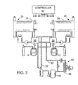
- FIGURE 3 is a diagram of a beverage dispensing system with a plurality of dispensers.
- a beverage dispensing system 10 receives a fully mixed carbonated beverage, such as beer or soda, from a keg 12.
- the keg is stored in a refrigerator which in the case of beer maintains the keg at a temperature of approximately 38 °F (3°C).
- a source of pressurized gas for example a cylinder 14 of carbon dioxide, is connected by a pressure regulator 16 to an inlet of the keg 12.
- the pressure regulator 16 controls the pressure of the carbon dioxide which is applied to the keg 12 and typically that pressure is set at 15 psi (1 bar) for beer.
- a compressor or other apparatus can be used to apply pressurized gas to the inlet of the keg 12.
- the keg pressure is commonly referred to as the "rack" pressure, and cylinder 14 can be connected to several kegs within the establishment at which the beverages are being served.
- the application of pressure to the keg 12 forces the beverage from an outlet through a supply conduit 18.
- An exterior wall of the reservoir 26 forms an outer cavity 30 extending around the inner chamber 28.
- Chilled liquid coolant such as glycol
- Baffles may be provided within the outer cavity 30 to ensure that the coolant flows completely around the inner chamber 28 to maintain the beverage 38 therein at a relatively uniform temperature.
- the coolant flows from the outer cavity 30 via an outlet line 34 into a coolant tank 31 from which a pump 32 forces the coolant through another coil within the chiller 20.
- a coolant with a relatively low freezing point such as glycol
- the temperature of the liquid in the outer cavity 30 can be lower than that of ice water baths of prior beverage dispensers. This counteracts heat loss to the ambient environment of the dispenser 25.
- the beverage 38 partially fills the inner chamber 28 of the reservoir 26 to a height that is detected by a level sensor 40.
- the upper portion 42 of the closed inner chamber 28 is filled with a mixture of air and carbon dioxide which outgases from the beverage.
- a breather tube 44 extends between the inner chamber 28 and the ambient atmosphere and has a pressure control valve 46 that is operated by an actuator 48. As will be described, the pressure control valve 46 is opened to vent the gas, beverage foam, or both from the inner chamber 28 into the ambient environment.
- a filter 45 may be provided to trap any contaminate from entering the reservoir through the breather tube 44.
- the valves 24 and 46 are operated electrically by signals from the controller 50 in response to the signal from the level sensor 40.
- the controller 50 has a standard hardware design that is based on a microcomputer and a memory in which the programs and data for execution by the microcomputer are stored.
- the microcomputer is connected input and output circuits that interface the controller to switches, sensors and valves of the beverage dispenser 10.
- the software executed by the controller responds to those input signals by operating the valves 24 and 46, as will be described.
- the reservoir 26 includes a dispensing spout 52 extending downwardly there from.
- the flow of beverage through the spout 52 is controlled by a movable dispensing valve element 53 that is mounted at the lower end of a tube which extends vertically through the spout 52 and the reservoir 26.
- An upper end of the tube 54 passes through a seal 55 and is connected to an actuator 56, which raises and lowers the tube. That motion brings the dispensing valve element 53 into and out of engagement with the spout 52 to allow beverage to flow into a serving container 59 placed there beneath.
- the actuator 56 is operated by signals from the controller 50, as will be described.
- a switch 58 is mounted on the valve element 53 and is depressed by the bottom of a serving container 59 placed under the spout 52 and raised upward.
- the switch 58 is connected by a pair of wires which runs through the tube 54, emerge from the actuator 56 and extend to an input of the controller 50.
- the pressure control valve 46 While the beverage 38 is being held in the reservoir 26 the pressure control valve 46 is closed so that the reservoir is sealed from the atmosphere surrounding the dispenser.
- the operator presses a pushbutton switch on a control panel 51 to designate the size of the serving container.
- the container 59 then is placed under the spout 52 and moved upward to activate a switch 58 mounted on the valve element 53 which sends a signal to the controller 50.
- the controller 50 reacts by opening the pressure control valve 46 to vent the pressure within the inner chamber 28 through the breather tube 44 to the outside atmosphere. This decreases the pressure within inner chamber 28 from the holding pressure to a lower dispensing pressure which is substantially equal to atmospheric pressure.
- the controller 50 powers the actuator 56 to open the valve element 53 for a predefined period of time required to fill the serving container 59. Lowering the pressure of the beverage prior to opening the spout valve element 53 reduces foaming within the serving container 59.
- the chiller 20 has an annular cylindrical housing 70 with coaxial inner and outer cylindrical walls 71 and 72 that are spaced apart to form a chamber 73 there between.
- the top and bottom ends of the chamber 73 are sealed by flat annular caps 75 and 76 extending between and welded to the inner and outer cylindrical walls 71 and 72.
- First and second coils 77 and 78 of tubing are wound within the inner chamber 73 and have inlets and outlets at the opposite ends of the housing 70.
- the inlet to the first tubing coil 77 is connected to the supply conduit 18 which carries the beverage from the keg 12 and the outlet of the first tubing coil is coupled to the beverage conduit 22 leading to the reservoir 26.
- the second tubing coil 78 serves to chill the coolant for the reservoir 26.
- the outlet conduit 33 of the pump 32 is connected to the inlet of the second tubing coil 78, which has an outlet attached to the coolant supply conduit 36 to the reservoir 26.
- the beverage conduit 22, coolant supply conduit 36 and the coolant return conduit 34 extend through an outer sheath 74 between the chiller 20 and the reservoir 26.
- the outer sheath 74 causes the supply conduit 36 to be in substantial contact with the beverage conduit 22 so that the chilled coolant maintains the beverage to the desired serving temperature.
- the outer sheath 74 can form part of the coolant supply conduit 36 so that the coolant flows around the beverage conduit 22 extending through the sheath.
- the coolant return conduit 34 feds the coolant into the tank 31 which has a first temperature sensor 79 that provides an input signal to the controller 50.
- the chiller housing 70 is filled with a refrigerant, which surrounds the first and second tubing coils 77 and 78 thus providing a refrigerant bath in which those coils are submerged.
- a refrigerant is a substance which transfers heat by changing between vapor and liquid states. Any commercially available refrigerant may be used, such as for example R-11, R-12, R-22, R-123, R-134a, R-401a, R-401b, R-404A, R-408A, R-409A, R-502, or R-717 (ammonia) as designated by the American Society of Heating Refrigeration and Air Conditioning Engineers (ASHRAE).
- ASHRAE American Society of Heating Refrigeration and Air Conditioning Engineers
- the chiller housing 70 thus functions as an evaporator of a refrigeration system.
- a second temperature sensor 94 is mounted to the chiller housing 70 to provide an input signal indicating the temperature of the refrigerant therein. Because the temperature of the refrigerant is related to its pressure, the second temperature sensor 94 could be replaced by a pressure probe to provide an input signal to the controller 50.
- the vapor phase refrigerant travels to the top section of the housing 70 and into an outlet formed by a low velocity stack 81.
- the low velocity stack 81 calms the bath of liquid refrigerant in the housing 70, thereby preventing a high velocity fluid flow from the chamber 73 into a return conduit 82.
- Such high velocity flow could carry the liquid refrigerant to the refrigerant condensing unit 80. It is desirable that refrigerant in only the vapor phase enter the return conduit 82 in order to maximize the cooling function of the chiller 20.
- refrigerant vapor is drawn from the low velocity stack 81 through the return conduit 82 into the refrigerant condensing unit 80.
- the refrigerant vapor enters an accumulator 86 from which it continues to flow to a conventional compressor 84 that has the outlet connected to a condenser 88.
- the condenser 88 is a coil through which a motorized fan assembly 90 blows air to remove heat from the refrigerant flowing therein. That transfer of heat and the increased pressure converts the refrigerant from vapor phase to liquid phase.
- the liquid refrigerant then flows from the condenser 88 through a conventional thermal expansion valve 89 and a return conduit 92 connected to an inlet of the chamber 73 at a bottom section of the chiller housing 70 thereby completing a standard refrigeration cycle.
- a bypass valve 83 is connected between the outlet of the compressor 84 and the return conduit 92. The bypass valve 83 is driven by a stepper motor that is operated by the controller 50.
- bypass valve When the flow rate of beverage is relatively low, the bypass valve is opened wide to increase the system heat load. When large amounts of beverage are being dispensed the bypass valve 83 is closed so that the chiller 20 will properly cool beverage rapidly flowing through the coil 77. Alternatively the controller 50 can turn off the compressor 84 during periods of low beverage flow as indicated by a refrigerant temperature in the chiller housing 70 that is below a defined level.
- the controller monitors the temperature of the coolant in the tank 31 as indicated by the first temperature sensor 79. This indication is more representative of the dispensing temperature of the beverage. However, control of the refrigeration system still must employ the temperature signal from the second sensor 94, as that signal indicates the temperature of the refrigerant and is required to prevent the beverage from freezing in the chiller 20.
- the velocity of the refrigerant vapor flowing from the chiller housing 70 in conduit 82 is relatively slow compared to conventional refrigeration systems in order to prevent liquid refrigerant from being drawn from the chiller housing 70. Consequently, that refrigerant vapor flow does not carry compressor oil that has entered the chiller housing from the refrigerant condensing unit 80 and that oil tends to accumulate at the bottom of the chiller housing 70 because the oil is denser than the refrigerant. If this oil is allowed to accumulate in the chiller housing, the compressor 84 will not be properly lubricated and eventually will seize-up. To avoid this problem, a small oil return tube 85 with a filter 87 is provided to drain the oil from the bottom of the chiller housing 70, and return it to the compressor 84. The pressure drop between the chiller 70 and the accumulator 86, created by the compressor 84, draws the oil from the chiller 20 into the compressor. The small diameter of the oil return tube 85 precludes a significant amount of liquid refrigerant from flowing there through.
- a single refrigerant condensing unit 80 can be connected via conduits 82 and 92 to several chillers 20 for different beverages. Specifically, different beverages are stored in kegs 12, each of which is connected through a separate chiller 20 to individual dispensers 25 for each beverage. Alternatively, multiple beverage and coolant coils 77 and 78 can be placed inside the same chiller housing 70 to service several beverage dispensers 25.
Landscapes
- Engineering & Computer Science (AREA)
- Physics & Mathematics (AREA)
- Thermal Sciences (AREA)
- Mechanical Engineering (AREA)
- General Engineering & Computer Science (AREA)
- Chemical & Material Sciences (AREA)
- Combustion & Propulsion (AREA)
- Devices For Dispensing Beverages (AREA)
- Devices That Are Associated With Refrigeration Equipment (AREA)
Applications Claiming Priority (2)
| Application Number | Priority Date | Filing Date | Title |
|---|---|---|---|
| US317257 | 2002-12-11 | ||
| US10/317,257 US6681594B1 (en) | 2002-12-11 | 2002-12-11 | Refrigeration apparatus for cooling a beverage |
Publications (2)
| Publication Number | Publication Date |
|---|---|
| EP1431238A2 true EP1431238A2 (fr) | 2004-06-23 |
| EP1431238A3 EP1431238A3 (fr) | 2004-08-25 |
Family
ID=30115397
Family Applications (1)
| Application Number | Title | Priority Date | Filing Date |
|---|---|---|---|
| EP03257688A Withdrawn EP1431238A3 (fr) | 2002-12-11 | 2003-12-06 | Appareil frigorifique pour refroidir des boisson |
Country Status (3)
| Country | Link |
|---|---|
| US (1) | US6681594B1 (fr) |
| EP (1) | EP1431238A3 (fr) |
| CA (1) | CA2452093C (fr) |
Cited By (1)
| Publication number | Priority date | Publication date | Assignee | Title |
|---|---|---|---|---|
| JP2017514099A (ja) * | 2014-04-25 | 2017-06-01 | フランケ・テクノロジー・アンド・トレードマーク・リミテッドFranke Technology And Trademark Ltd. | 熱交換器 |
Families Citing this family (25)
| Publication number | Priority date | Publication date | Assignee | Title |
|---|---|---|---|---|
| US7337624B2 (en) | 2003-03-27 | 2008-03-04 | The Coca-Cola Company | Refrigeration system and method for beverage dispenser |
| FR2877661A1 (fr) * | 2004-11-10 | 2006-05-12 | Pierre Raymond Lacombe | Appareil de refrigeration et de tirage tempere de biere ou toutes autres boissons conditionnees en fut |
| AU2012203078B2 (en) * | 2005-04-06 | 2013-08-01 | The Coca-Cola Company | Refrigeration system and method for beverage dispenser |
| CN101401048B (zh) | 2005-12-15 | 2010-12-01 | 尼亚加拉分装技术股份有限公司 | 饮料分配 |
| US20070193653A1 (en) * | 2005-12-15 | 2007-08-23 | Thomas Gagliano | Beverage dispenser |
| EP1969265B1 (fr) * | 2005-12-15 | 2015-09-16 | DD Operations Ltd. | Regulation numerique de debit |
| WO2008016347A1 (fr) * | 2006-08-01 | 2008-02-07 | Carrier Corporation | Conception modulaire de soupape de compresseur pour système de fluide frigorigène |
| US7823411B2 (en) | 2006-12-15 | 2010-11-02 | Niagara Dispensing Technologies, Inc. | Beverage cooling system |
| US20080142115A1 (en) * | 2006-12-15 | 2008-06-19 | Niagara Dispensing Technologies, Inc. | Beverage dispensing |
| US20080202148A1 (en) * | 2007-02-27 | 2008-08-28 | Thomas Gagliano | Beverage cooler |
| US20080289357A1 (en) * | 2007-05-22 | 2008-11-27 | Skobel Robert M | Liquid nitrogen cooled beverage dispenser |
| US8495893B2 (en) * | 2009-01-08 | 2013-07-30 | Ali Alajimi | Hybrid apparatus for cooling water and air and heating water |
| EA201491428A1 (ru) * | 2012-01-27 | 2014-11-28 | Зе Шуэ Чил Компани Лимитед | Холодильный аппарат |
| CN102734995B (zh) * | 2012-06-29 | 2014-10-08 | 美的集团股份有限公司 | 空调和调温箱一体机的控制方法 |
| CN103968478B (zh) * | 2013-02-01 | 2018-02-23 | Lg电子株式会社 | 冷却系统及其控制方法 |
| GB2519384B (en) | 2013-10-15 | 2020-07-01 | Streamline Beverage Pty Ltd | A beverage dispenser |
| US11124406B1 (en) * | 2014-07-13 | 2021-09-21 | Sestra Systems, Inc. | System and method for piston detection in a metering mechanism for use with beverage dispensing system |
| CN104500367A (zh) * | 2014-12-19 | 2015-04-08 | 苏州市东华试验仪器有限公司 | 一种压缩机组 |
| CN108351146B (zh) | 2015-09-11 | 2021-04-20 | 确保冷藏有限公司 | 便携式制冷设备 |
| GB2584322B (en) * | 2019-05-30 | 2022-12-07 | Douwe Egberts Bv | Apparatus and method for preparing an iced tea or coffee beverage |
| GB2584319B (en) * | 2019-05-30 | 2023-05-03 | Douwe Egberts Bv | Apparatus and method for preparing an iced tea or coffee beverage |
| GB2602584B (en) * | 2022-03-18 | 2023-01-04 | Brass Monkey Health Ltd | An ice bath |
| CN119894414A (zh) * | 2022-09-22 | 2025-04-25 | 雀巢产品有限公司 | 饮料分配器 |
| AT527206B1 (de) * | 2023-10-11 | 2024-12-15 | One Two Beer Gmbh | Vorrichtung zum Ausschenken eines kohlensäurehaltigen Getränks |
| AT527207B1 (de) * | 2023-10-11 | 2024-12-15 | One Two Beer Gmbh | Vorrichtung zum Ausschenken eines kohlensäurehaltigen Getränks |
Family Cites Families (19)
| Publication number | Priority date | Publication date | Assignee | Title |
|---|---|---|---|---|
| CH176128A (de) * | 1934-06-30 | 1935-03-31 | Sulzer Ag | Ortsbeweglicher Flüssigkeitsbehälter, insbesondere Verdampfer für Schiffskältemaschinen. |
| US2143961A (en) * | 1935-05-09 | 1939-01-17 | Commercial Coil & Refrigeratio | Refrigerating apparatus |
| US2646667A (en) * | 1949-10-15 | 1953-07-28 | Wallace R Kromer | Method of and apparatus for storing, cooling, and dispensing beverages |
| US3435631A (en) * | 1967-08-17 | 1969-04-01 | Midwest Research & Dev Corp | Two-stage evaporative condenser |
| AT317028B (de) | 1971-04-30 | 1974-08-12 | Getraenke Ges M B H | Verfahren und Einrichtung zur Förderung von gashaltigen Flüssigkeiten |
| NL7308179A (fr) | 1972-06-20 | 1973-12-27 | ||
| US3978900A (en) | 1973-12-17 | 1976-09-07 | Fmc Corporation | Carbonated beverage filler |
| US4560089A (en) | 1981-05-11 | 1985-12-24 | The Cornelius Company | Apparatus for dispensing a carbonated beverage |
| DE3435725A1 (de) | 1984-09-28 | 1986-04-10 | Bartholomäus 8024 Deisenhofen Gmeineder | Verfahren zum zapfen von bier, insbesondere weissbier, in trinkgefaesse |
| GB2231133B (en) * | 1989-04-04 | 1992-08-12 | Star Refrigeration | Oil recovery in refrigeration system |
| PT672875E (pt) * | 1994-03-15 | 2000-11-30 | Mitsubishi Electric Corp | Sistema de ar condicionado, acumulador para o mesmo e processo para a fabricacaodo acumulador |
| KR100279217B1 (ko) * | 1994-04-13 | 2001-02-01 | 야마자끼 순페이 | 반도체 장치 형성 방법, 결정성 반도체 막 형성 방법, 박막 트랜지스터 형성 방법 및 반도체 장치 제조 방법 |
| GB2289938B (en) * | 1994-05-27 | 1998-03-04 | Imi Cornelius Deutschland Gmbh | Beverage cooling |
| US5603363A (en) | 1995-06-20 | 1997-02-18 | Exel Nelson Engineering Llc | Apparatus for dispensing a carbonated beverage with minimal foaming |
| US5566732A (en) | 1995-06-20 | 1996-10-22 | Exel Nelson Engineering Llc | Beverage dispenser with a reader for size indica on a serving container |
| EP0861801A1 (fr) | 1997-02-27 | 1998-09-02 | Whitbread Plc | Robinet distributeur de boissons |
| US6237652B1 (en) | 2000-01-25 | 2001-05-29 | Dispensing Systems, Inc. | Pressurized system and method for dispensing carbonated beverage |
| WO2002023105A1 (fr) * | 2000-09-15 | 2002-03-21 | Mile High Equipment Company | Machine a glace silencieuse |
| US6530400B2 (en) * | 2001-02-20 | 2003-03-11 | Dispensing Systems International, Inc. | Intermediate pressure dispensing method for a carbonated beverage |
-
2002
- 2002-12-11 US US10/317,257 patent/US6681594B1/en not_active Expired - Fee Related
-
2003
- 2003-12-05 CA CA002452093A patent/CA2452093C/fr not_active Expired - Fee Related
- 2003-12-06 EP EP03257688A patent/EP1431238A3/fr not_active Withdrawn
Cited By (1)
| Publication number | Priority date | Publication date | Assignee | Title |
|---|---|---|---|---|
| JP2017514099A (ja) * | 2014-04-25 | 2017-06-01 | フランケ・テクノロジー・アンド・トレードマーク・リミテッドFranke Technology And Trademark Ltd. | 熱交換器 |
Also Published As
| Publication number | Publication date |
|---|---|
| US6681594B1 (en) | 2004-01-27 |
| CA2452093C (fr) | 2007-01-02 |
| EP1431238A3 (fr) | 2004-08-25 |
| CA2452093A1 (fr) | 2004-06-11 |
Similar Documents
| Publication | Publication Date | Title |
|---|---|---|
| US6681594B1 (en) | Refrigeration apparatus for cooling a beverage | |
| US20250214825A1 (en) | Single tank carbonation for carbonated soft drink equipment | |
| US5535600A (en) | Cooling system for a post-mix beverage dispenser | |
| US6761036B2 (en) | Beverage dispenser with integral ice maker | |
| RU2493509C2 (ru) | Стоечная колонка, устройство для розлива и способ регулировки температуры напитка | |
| US4437319A (en) | Beverage dispensing device | |
| KR20090122449A (ko) | 음료 냉각 장치 및 방법 | |
| GB2242332A (en) | Cooling system for remotely dispensed beverages | |
| RU2309117C2 (ru) | Подача разливных напитков | |
| US5946918A (en) | Cooling of stored water | |
| US6164083A (en) | Liquid temperature regulating apparatus | |
| US5732856A (en) | Beverage conveyance system between beverage storage and dispensing | |
| EP3309116B1 (fr) | Tireuse de bière pression à double refroidissement | |
| US5372014A (en) | Modular cooling system for multiple spaces and dispensed beverages | |
| US2292692A (en) | Liquid refrigerating unit | |
| JP3807958B2 (ja) | ビール等の清涼飲料水のディスペンサー | |
| AU2005202247A1 (en) | Rapid comestible fluid dispensing apparatus and method | |
| US6981441B1 (en) | Fresh brewed ice beverage dispensing system | |
| JP2011031918A (ja) | 飲料供給装置 | |
| WO2006123199A1 (fr) | Systeme de distribution de boissons alcoolisees refrigerees multiples | |
| JP3600807B2 (ja) | ビール等の清涼飲料水のディスペンサー | |
| US20140131382A1 (en) | Household appliance with beverage dispensing system, method and filter cartridge | |
| EP2310779A1 (fr) | Appareil de soutirage et son circuit de refroidissement | |
| JPH01213194A (ja) | 飲料自動販売システム | |
| NZ777615B2 (en) | Method and apparatus for dispensing a beverage in chilled condition |
Legal Events
| Date | Code | Title | Description |
|---|---|---|---|
| PUAI | Public reference made under article 153(3) epc to a published international application that has entered the european phase |
Free format text: ORIGINAL CODE: 0009012 |
|
| AK | Designated contracting states |
Kind code of ref document: A2 Designated state(s): AT BE BG CH CY CZ DE DK EE ES FI FR GB GR HU IE IT LI LU MC NL PT RO SE SI SK TR |
|
| AX | Request for extension of the european patent |
Extension state: AL LT LV MK |
|
| PUAL | Search report despatched |
Free format text: ORIGINAL CODE: 0009013 |
|
| AK | Designated contracting states |
Kind code of ref document: A3 Designated state(s): AT BE BG CH CY CZ DE DK EE ES FI FR GB GR HU IE IT LI LU MC NL PT RO SE SI SK TR |
|
| AX | Request for extension of the european patent |
Extension state: AL LT LV MK |
|
| AKX | Designation fees paid |
Designated state(s): AT BE BG CH CY CZ DE DK EE ES FI FR GB GR HU IE IT LI LU MC NL PT RO SE SI SK TR |
|
| STAA | Information on the status of an ep patent application or granted ep patent |
Free format text: STATUS: THE APPLICATION IS DEEMED TO BE WITHDRAWN |
|
| 18D | Application deemed to be withdrawn |
Effective date: 20050226 |