EP1431468B1 - Section du bâtiment avec des éléments de double parois et procédé de construction - Google Patents
Section du bâtiment avec des éléments de double parois et procédé de construction Download PDFInfo
- Publication number
- EP1431468B1 EP1431468B1 EP02027887A EP02027887A EP1431468B1 EP 1431468 B1 EP1431468 B1 EP 1431468B1 EP 02027887 A EP02027887 A EP 02027887A EP 02027887 A EP02027887 A EP 02027887A EP 1431468 B1 EP1431468 B1 EP 1431468B1
- Authority
- EP
- European Patent Office
- Prior art keywords
- segment
- segments
- floor panel
- side wall
- panel
- Prior art date
- Legal status (The legal status is an assumption and is not a legal conclusion. Google has not performed a legal analysis and makes no representation as to the accuracy of the status listed.)
- Expired - Lifetime
Links
Images

Classifications
-
- E—FIXED CONSTRUCTIONS
- E04—BUILDING
- E04B—GENERAL BUILDING CONSTRUCTIONS; WALLS, e.g. PARTITIONS; ROOFS; FLOORS; CEILINGS; INSULATION OR OTHER PROTECTION OF BUILDINGS
- E04B1/00—Constructions in general; Structures which are not restricted either to walls, e.g. partitions, or floors or ceilings or roofs
- E04B1/16—Structures made from masses, e.g. of concrete, cast or similarly formed in situ with or without making use of additional elements, such as permanent forms, substructures to be coated with load-bearing material
- E04B1/161—Structures made from masses, e.g. of concrete, cast or similarly formed in situ with or without making use of additional elements, such as permanent forms, substructures to be coated with load-bearing material with vertical and horizontal slabs, both being partially cast in situ
-
- E—FIXED CONSTRUCTIONS
- E04—BUILDING
- E04C—STRUCTURAL ELEMENTS; BUILDING MATERIALS
- E04C2/00—Building elements of relatively thin form for the construction of parts of buildings, e.g. sheet materials, slabs, or panels
- E04C2/02—Building elements of relatively thin form for the construction of parts of buildings, e.g. sheet materials, slabs, or panels characterised by specified materials
- E04C2/04—Building elements of relatively thin form for the construction of parts of buildings, e.g. sheet materials, slabs, or panels characterised by specified materials of concrete or other stone-like material; of asbestos cement; of cement and other mineral fibres
- E04C2/044—Building elements of relatively thin form for the construction of parts of buildings, e.g. sheet materials, slabs, or panels characterised by specified materials of concrete or other stone-like material; of asbestos cement; of cement and other mineral fibres of concrete
-
- E—FIXED CONSTRUCTIONS
- E04—BUILDING
- E04C—STRUCTURAL ELEMENTS; BUILDING MATERIALS
- E04C2/00—Building elements of relatively thin form for the construction of parts of buildings, e.g. sheet materials, slabs, or panels
- E04C2/30—Building elements of relatively thin form for the construction of parts of buildings, e.g. sheet materials, slabs, or panels characterised by the shape or structure
- E04C2/34—Building elements of relatively thin form for the construction of parts of buildings, e.g. sheet materials, slabs, or panels characterised by the shape or structure composed of two or more spaced sheet-like parts
Definitions
- the present invention relates to a building floor part with a base plate and at least one sidewall segment made of one with concrete poured double wall element, which on the edge of the base plate this is put on.
- the invention also relates to a building floor several such building storey parts and a method for manufacturing of a building floor.
- a disadvantage of all the previously known systems with the combination of Double wall elements and in-situ concrete is made of waterproof concrete, and that the floor slab and the walls are not concreted in one operation can.
- the concreting joint remains between the floor slab and the walls exist as an absolute weak point, which requires additional seals. At the same time, this creates higher constraints with one higher reinforcement requirements.
- the present invention is therefore based on the object of one possibility to propose, in which within one day the floor slab together with the Walls and possibly also ceilings can be made, but additionally none Concrete joint is created as a weak point.
- the base plate is made of at least one Base plate segment designed as a double wall element and the Space in the double walls of the floor slab segment and one or several sidewall segments are filled with concrete throughout.
- the Base plate at least with the walls, and if desired, also with the Blankets are made. Such parts of building floors and building floors for cellar rooms can be manufactured very inexpensively.
- Double wall elements can be used. Because basically the Base plate made up of one or more base plate segments and the individual Wall surfaces also from one side wall segment or more Sidewall segments can exist in the following for simplification the singular used.
- the double wall elements are of the base plate segment and the side wall segment from one first larger plate for the outside of the floor and a smaller one Plate made for the inside of the floor. Furthermore, they are in the dimensions matched so that the larger plate of the respective side wall segment on the larger plate of the Base plate segment and the smaller plate of each Sidewall segment stands on the smaller plate of the base plate segment. This creates the gaps between the prefabricated panels of each Double wall elements connected to each other in order to be combined with Concrete to be filled.
- the floor of the floor can consist of several such base plate segments be made. According to a further training at the joint between the base plate segments in the space in the double wall element covered. These joints are easily accessible because of the construction-related area a free space through the above-mentioned smaller plate of the Double wall element is created.
- the seal here, as well as at the joint in the outer area between the wall segment and the base plate segment, is done by a hot glued bitumen membrane. Subsequently, in reinforcement (connection reinforcement) is attached to this area and then poured out with concrete.
- the Floor ceiling can be made.
- the one for holding the floor ceiling necessary supports can be used through the use of double wall elements also for the floor slab area, without prior concreting be used.
- the floor slab are also advantageous the usual and well-known prefabricated ceiling panels with prepared reinforcement used and placed on the double wall elements of the wall segments so that the space between the double walls is not covered. Then can do the same in a concreting process with appropriate concrete pumps Side walls, the floor slab and the ceiling are concreted so that the entire basement has a continuously connected concrete core. This contributes to the particular stability and cost-effective production.
- the production of a building floor takes place at least one base plate segment, several side wall segments and at least one ceiling segment, with the bottom wall segments and the Sidewall segments as double wall elements with different sizes Wall panels and the ceiling elements are designed as prefabricated panels, such as described below. It is assumed that the surface for the Base plate is prepared in the usual and known manner.
- the underground points expediently a gravel filter and a lean concrete layer.
- the side walls with the larger wall plate facing out onto the or the base plate segments set up in such a way that the smaller wall plates and the larger wall panels are assigned to each other and the space connected between the base plate segments and the wall segments becomes.
- the ceiling segments are placed on the wall segments without that the space between the double wall elements and the Sidewall segments is closed. This is followed by Pour the base plate segments and the surface of the Ceiling segments essentially at the same time as a waterproof one Concrete, for example waterproof concrete.
- the concrete in the floor slab segments is specially designed for this provided openings compressed.
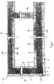
- Figure 1 shows two base plate segments 1, 2 and one on the left Base plate segment 2 set up side wall segment 3. Such segments usually have a maximum width of 3 m and a length of 7 - 8 m each after request.
- the invention is exemplary in connection explained with the segments 1 - 3 shown.
- a complete floor of course consists of several side wall segments 3 and can also have a multiplicity of base plate segments 1, 2.
- All segments 1 - 3 are designed and exist as double wall elements from a larger outer prefabricated panel 4 and an inner smaller one Prefabricated panel 5. These are connected to each other via a lattice reinforcement 6.
- the dimensions of the base plate segments 1, 2 and the side wall segments 3 with regard to the thickness can be according to the requirements be adjusted. When made in the factory, the size is the smaller Prefabricated panel 5 at the base plate segments 1, 2 to the thickness of the Side wall elements 3 and vice versa.
- the side wall segments 3 are so on the Base plate segment 1 placed that the precast plate 4 of the side wall segment 3 on the precast plate 4 of the base plate segment and the Prefabricated panel 5 of the side wall segment 3 on the prefabricated panel 5 of the Floor plate segment 1 stands.
- a connecting reinforcement 7 can be introduced as a corner connection.
- the prefabricated panel 5 of the floor panel segments 1, 2 has openings 8 which in the figure are schematic and not indicated to scale. These openings serve to feed the in-situ concrete and the subsequent shaking and Compacting the concrete. After completion, these openings 8 locked.
- bitumen sheet 10 By placing the two base plate segments 1, 2 together above the joint 9 between the two outer panels 4 of the two base plate segments 1, 2, a space through which the joint a bitumen sheet 10 can be applied hot glued to the passage to prevent moisture or water at this point.
- a corresponding Bitumen sheet 12 is also at the joint 11 between the prefabricated panel 4 of the Sidewall segment 3 and the precast plate 4 of the base plate segment 1 arranged hot glued.
- Figure 2 shows a part of a concrete already poured Projectile with the segments 1 - 3 already explained in FIG. 1.
- a load-bearing inner wall 16 which is exemplary here is also made of concrete. This supports the floor ceiling 17, the also consists of a precast plate provided with a reinforcement 18 and was concreted in when the space was poured. So that will one floor with a complete, continuous concrete core composite manufactured that has no joints that need to be specially revised.
- the prefabricated panel 19 of the floor ceiling 17 is located on a second sidewall segment.
- the support can be used without a previous concreting is required by corresponding yourself on the Precast plate 5 of the respective base plate segment 1 does not support shown building supports.
Landscapes
- Engineering & Computer Science (AREA)
- Architecture (AREA)
- Civil Engineering (AREA)
- Structural Engineering (AREA)
- Physics & Mathematics (AREA)
- Electromagnetism (AREA)
- Panels For Use In Building Construction (AREA)
- Building Environments (AREA)
- Finish Polishing, Edge Sharpening, And Grinding By Specific Grinding Devices (AREA)
- Rod-Shaped Construction Members (AREA)
- Finishing Walls (AREA)
Claims (14)
- Section d'étage de bâtiment, avec une plaque de sol et au moins un segment de paroi latérale, formée d'un élément à double paroi (3) coulé en béton, posé sur le bord de la plaque de sol, sur celle-ci, caractérisée en ce que la plaque de sol est formée d'au moins un segment de plaque de sol (1, 2), réalisé sous la forme d'élément à double paroi, et l'espace intermédiaire (15), se trouvant dans les doubles parois du segment de plaque de sol (1, 2), et un ou plusieurs éléments de paroi latérale (3) étant remplis de béton, de façon continue, en donnant un produit composite.
- Section d'étage de bâtiment selon la revendication 1, caractérisée en ce que les éléments à double paroi du segment de plaque de sol (1, 2) et du segment de paroi latérale (3) sont formés d'une première plus grande plaque (4) pour la face extérieure de l'étage et d'une plus petite plaque (5) pour la face intérieure de l'étage, et sont mutuellement adaptés au niveau des dimensions, de manière que la plus grande plaque (4) du segment de paroi latérale (3) respectif se place sur la plus grande plaque (4) du segment de plaque de sol (1, 2) et que la plus petite plaque (5) du segment de paroi latérale (3) respectif se place sur la plus petite plaque (4) du segment de plaque de sol (1, 2).
- Section d'étage de bâtiment selon l'une des revendications précédentes, caractérisée en ce que, du côté intérieur de l'étage, le segment de plaque de sol (1, 2) présente des ouvertures (8) disposées à distance les unes des autres, donnant vers l'espace intermédiaire (15) se trouvant entre les doubles parois.
- Section d'étage de bâtiment selon l'une des revendications précédentes, caractérisée en ce que le sol de l'étage est fabriqué à partir d'une pluralité de tels segments de plaque de sol (1, 2).
- Section d'étage de bâtiment selon la revendication 4, caractérisée en ce que l'endroit de jointoiement (9), entre les segments de plaque de sol (1, 2), est couvert dans l'espace intermédiaire (15) formé dans les éléments de double paroi.
- Section d'étage de bâtiment selon l'une des revendications précédentes, caractérisée en ce que l'endroit de jointoiement (11), entre le segment de paroi latérale (3) et le segment de plaque de sol (1) respectif, est couvert extérieurement.
- Section d'étage de bâtiment selon la revendication 5 ou 6, caractérisés en ce que l'endroit de jointoiement (9, 10) est couvert par une bande de bitume (10, 11), collée à chaud.
- Section d'étage de bâtiment selon l'une des revendications précédentes, caractérisée en ce que, sur le segment de paroi latérale (3), est disposé un segment de plafond (17), présentant, en face inférieure, une plaque partielle terminée (19), et la couche de béton (20), appliquée sur la plaque partielle terminée (19), est reliée de façon continue au béton (21) se trouvant dans les segments à double paroi.
- Section d'étage de bâtiment formée d'une pluralité de parties d'étages de bâtiment selon la revendication 1 ou 2, caractérisée par au moins un segment de plaque de sol (1, 2), au moins quatre segments de paroi latérale (3) et au moins un segment de plafond (17), formé d'une plaque partielle terminée (19), faisant office de face inférieure, dans lesquels le béton (21) situé dans les espaces intermédiaires (15), dans les doubles parois, et celui d'une couche en béton (20), située sur le segment de plafond (17), sont réalisés sous la forme d'une couche en béton composite.
- Procédé de fabrication d'un étage de bâtiment, formé d'au moins un segment de plaque de sol (1, 2), d'une pluralité de segments de paroi latérale (3) et d'au moins un segment de plafond (17), les segments de paroi de sol (1, 2) et les segments de paroi latérale (3) étant réalisés sous la forme d'éléments à double paroi, avec des plaques de paroi (4, 5) de taille différente, et les éléments de plafond (17) étant réalisés en tant que plaque partielle terminée (19) avec une armature, présentant les étapes suivantes :pose d'au moins un segment de plaque de sol (1, 2), ayant la plus grande plaque de paroi (4), sur une base préparée;érection des segments de paroi latérale (3), ayant la plaque de paroi (4) plus grande, vers l'extérieur, sur le segment de plaque de sol (1, 2) chaque fois afférent;pose des segments de plafond (17) sur les segments de paroi latérale (3), sans recouvrement de l'espace intermédiaire (15) se trouvant entre les segments de paroi latérale (3); etcoulée des segments de plaque de sol (1, 2) et des segments de paroi latérale (3), ainsi que de la surface des segments de plafond (17), lors d'une étape opératoire de bétonnage continue.
- Procédé selon la revendication 10, caractérisé en ce que, pendant la coulée, le béton est compacté dans les segments de plaque de sol (1, 2), au moyen d'ouvertures (8) prévues à cet effet.
- Procédé selon l'une des revendications 10 ou 11 précédentes, caractérisé en ce que, avant l'érection des segments de paroi latérale (3), on introduit une armature de raccordement (7) formée à angle droit.
- Procédé selon l'une des revendications 10 à 12 précédentes, caractérisé en ce que l'endroit de jointoiement (9), entre les plus grandes plaques de paroi (5) des segments de plaques de fond (1, 2), est avant la coulée, isolé hermétiquement pour empêcher toute entrée d'humidité et une armature de raccordement (14) est ensuite introduite dans cette zone d'espace intermédiaire (13).
- Procédé selon l'une des revendications 11 à 13 précédentes, caractérisé en ce que les ouvertures (8), ménagées dans les segments de plaque de sol (1, 2), et les espaces intermédiaires (13), existant entre les segments de plaque de sol, sont fermés par mastiquage, de sorte que la surface du sol est lisse.
Applications Claiming Priority (2)
| Application Number | Priority Date | Filing Date | Title |
|---|---|---|---|
| DE20219324U | 2002-12-12 | ||
| DE20219324U DE20219324U1 (de) | 2002-12-12 | 2002-12-12 | Gebäudegeschoss |
Publications (2)
| Publication Number | Publication Date |
|---|---|
| EP1431468A1 EP1431468A1 (fr) | 2004-06-23 |
| EP1431468B1 true EP1431468B1 (fr) | 2004-08-11 |
Family
ID=7977938
Family Applications (1)
| Application Number | Title | Priority Date | Filing Date |
|---|---|---|---|
| EP02027887A Expired - Lifetime EP1431468B1 (fr) | 2002-12-12 | 2003-01-01 | Section du bâtiment avec des éléments de double parois et procédé de construction |
Country Status (3)
| Country | Link |
|---|---|
| EP (1) | EP1431468B1 (fr) |
| AT (1) | ATE273421T1 (fr) |
| DE (2) | DE20219324U1 (fr) |
Families Citing this family (6)
| Publication number | Priority date | Publication date | Assignee | Title |
|---|---|---|---|---|
| EP1457609B1 (fr) * | 2003-03-13 | 2005-06-29 | Glatthaar Fertigkeller GmbH | Plancher pour un bâtiment |
| EP1482098B1 (fr) * | 2003-05-26 | 2008-01-09 | Glatthaar Fertigkeller GmbH | Cave imperméable à l'eau et son procédé de construction |
| HRP20150337T1 (hr) * | 2007-02-10 | 2015-04-24 | Kappema Fertigteilindustrie Gmbh | Konstrukcijski element koji sadrži unutarnju oplatu |
| DE102007011557A1 (de) * | 2007-02-27 | 2008-09-04 | Jens Döring | Vollgeschoßgebäude mit großen, flachen, freitragenden Gewölbe aus filigranen Stahlbetonfertigteilelementen, zu einem gesamt geschlossenen, homogenen und dichten Baukörper |
| IT1400889B1 (it) * | 2010-07-08 | 2013-07-02 | Fornace Calandra S R L | Procedimento per realizzare una bilastra con fondazione. |
| CN113027023A (zh) * | 2021-04-02 | 2021-06-25 | 袁国强 | 一种装配式叠合楼板及该叠合楼板的施工方法 |
Family Cites Families (7)
| Publication number | Priority date | Publication date | Assignee | Title |
|---|---|---|---|---|
| CH399718A (fr) * | 1965-03-24 | 1965-09-30 | Comment Paul | Procédé de construction d'un bâtiment |
| DE1909204A1 (de) * | 1968-02-26 | 1969-11-27 | Rudolf Polan | Mantel-Bauweise |
| FR2021979A1 (fr) * | 1968-10-31 | 1970-07-24 | Gualandi Sergio | |
| FR2467923A2 (fr) * | 1971-11-15 | 1981-04-30 | Olle Jean Louis | Procede de construction a l'aide de panneaux prefabriques et construction ainsi realisee |
| DE19521262C2 (de) * | 1995-06-10 | 1998-12-17 | Christa Gmbh & Co Kg | Verfahren zum Herstellen einer Bauplatte |
| DE29805829U1 (de) * | 1998-03-31 | 1998-07-09 | Degen, Paul, 77830 Bühlertal | Wärmegedämmtes, hohlwandiges Bauteil |
| EP1046758A1 (fr) * | 1999-04-19 | 2000-10-25 | Rolf Bless | Procédé de construction d'une plaque en béton et du coffrage d'un mur, élément de coffrage préfabriqué |
-
2002
- 2002-12-12 DE DE20219324U patent/DE20219324U1/de not_active Expired - Lifetime
-
2003
- 2003-01-01 AT AT02027887T patent/ATE273421T1/de not_active IP Right Cessation
- 2003-01-01 EP EP02027887A patent/EP1431468B1/fr not_active Expired - Lifetime
- 2003-01-01 DE DE50300052T patent/DE50300052D1/de not_active Expired - Fee Related
Also Published As
| Publication number | Publication date |
|---|---|
| HK1066038A1 (en) | 2005-03-11 |
| ATE273421T1 (de) | 2004-08-15 |
| DE20219324U1 (de) | 2003-03-06 |
| EP1431468A1 (fr) | 2004-06-23 |
| DE50300052D1 (de) | 2004-09-16 |
Similar Documents
| Publication | Publication Date | Title |
|---|---|---|
| DE60023894T2 (de) | Paneel und verfahren zur herstellung von betonwänden | |
| DE102015106294A1 (de) | Vorrichtung und Verfahren zur Wärmeentkopplung von betonierten Gebäudeteilen | |
| DE2231943A1 (de) | Baukasteneinheit und verfahren zur herstellung eines gebaeudes nach einem baukastensystem | |
| EP1431468A1 (fr) | Section du bâtiment avec des éléments de double parois et procédé de construction | |
| DE69322662T2 (de) | Gebäudewand, verfahren zum errichten einer solchen wand und element hierfür | |
| DE102015200661B4 (de) | Verbundfertigteil | |
| AT527289B1 (de) | Bogenhaus | |
| DE2908995C2 (fr) | ||
| DE19920032A1 (de) | Herstellungs- und Montagesystem für Fertigteile von Gebäuden | |
| DE60206172T2 (de) | System zum herstellen von verlorenen schalungselementen für die schüttung von (stahl)beton | |
| WO1997013043A1 (fr) | Maison prefabriquee de construction en dur et modulaire | |
| EP1911882A2 (fr) | Système de fabrication d'un revêtement pour un toit, un sol ou analogue, sur lequel on peut marcher ou rouler. | |
| EP1319790B1 (fr) | Ancrage pour une fenêtre ou une porte | |
| EP1591595A2 (fr) | Cave étanche | |
| EP1457609B1 (fr) | Plancher pour un bâtiment | |
| DE102005028697B4 (de) | System zum Erstellen einer Gebäudewand | |
| DE10230963A1 (de) | Verfahren zur Herstellung einer tragenden Wand und ein entsprechendes Bauelement zur Durchführung des Verfahrens | |
| DE2422586A1 (de) | Fertigbetonteil und verfahren zu dessen herstellung | |
| EP1482098B1 (fr) | Cave imperméable à l'eau et son procédé de construction | |
| DE10046138C2 (de) | Fertigmodul für Gebäudeetagen eines Hauses und Verfahren zur Herstellung und Aufbau von Gebäudeteilen aus Fertigmodulen | |
| DE20301303U1 (de) | Gebäudefertigteil | |
| AT397401B (de) | Selbsttragende deckenplatte | |
| DE905883C (de) | Verfahren zur Herstellung insbesondere von Aussen- und Zwischenwaenden von Gebaeuden | |
| DE20311076U1 (de) | Wasserundurchlässiger Keller | |
| EP4707482A1 (fr) | Procédé de rénovation ou de création d'une loggia dans un bâtiment |
Legal Events
| Date | Code | Title | Description |
|---|---|---|---|
| GRAP | Despatch of communication of intention to grant a patent |
Free format text: ORIGINAL CODE: EPIDOSNIGR1 |
|
| GRAS | Grant fee paid |
Free format text: ORIGINAL CODE: EPIDOSNIGR3 |
|
| PUAI | Public reference made under article 153(3) epc to a published international application that has entered the european phase |
Free format text: ORIGINAL CODE: 0009012 |
|
| 17P | Request for examination filed |
Effective date: 20030322 |
|
| AK | Designated contracting states |
Kind code of ref document: A1 Designated state(s): AT BE BG CH CY CZ DE DK EE ES FI FR GB GR HU IE IT LI LU MC NL PT SE SI SK TR |
|
| AX | Request for extension of the european patent |
Extension state: AL LT LV MK RO |
|
| GRAA | (expected) grant |
Free format text: ORIGINAL CODE: 0009210 |
|
| AK | Designated contracting states |
Kind code of ref document: B1 Designated state(s): AT BE BG CH CY CZ DE DK EE ES FI FR GB GR HU IE IT LI LU MC NL PT SE SI SK TR |
|
| AX | Request for extension of the european patent |
Extension state: AL LT LV MK RO |
|
| PG25 | Lapsed in a contracting state [announced via postgrant information from national office to epo] |
Ref country code: TR Free format text: LAPSE BECAUSE OF FAILURE TO SUBMIT A TRANSLATION OF THE DESCRIPTION OR TO PAY THE FEE WITHIN THE PRESCRIBED TIME-LIMIT Effective date: 20040811 Ref country code: SK Free format text: LAPSE BECAUSE OF FAILURE TO SUBMIT A TRANSLATION OF THE DESCRIPTION OR TO PAY THE FEE WITHIN THE PRESCRIBED TIME-LIMIT Effective date: 20040811 Ref country code: SI Free format text: LAPSE BECAUSE OF FAILURE TO SUBMIT A TRANSLATION OF THE DESCRIPTION OR TO PAY THE FEE WITHIN THE PRESCRIBED TIME-LIMIT Effective date: 20040811 Ref country code: IE Free format text: LAPSE BECAUSE OF FAILURE TO SUBMIT A TRANSLATION OF THE DESCRIPTION OR TO PAY THE FEE WITHIN THE PRESCRIBED TIME-LIMIT Effective date: 20040811 Ref country code: GB Free format text: LAPSE BECAUSE OF FAILURE TO SUBMIT A TRANSLATION OF THE DESCRIPTION OR TO PAY THE FEE WITHIN THE PRESCRIBED TIME-LIMIT Effective date: 20040811 Ref country code: FI Free format text: LAPSE BECAUSE OF FAILURE TO SUBMIT A TRANSLATION OF THE DESCRIPTION OR TO PAY THE FEE WITHIN THE PRESCRIBED TIME-LIMIT Effective date: 20040811 Ref country code: EE Free format text: LAPSE BECAUSE OF FAILURE TO SUBMIT A TRANSLATION OF THE DESCRIPTION OR TO PAY THE FEE WITHIN THE PRESCRIBED TIME-LIMIT Effective date: 20040811 Ref country code: BG Free format text: LAPSE BECAUSE OF FAILURE TO SUBMIT A TRANSLATION OF THE DESCRIPTION OR TO PAY THE FEE WITHIN THE PRESCRIBED TIME-LIMIT Effective date: 20040811 |
|
| REG | Reference to a national code |
Ref country code: GB Ref legal event code: FG4D Free format text: NOT ENGLISH |
|
| REG | Reference to a national code |
Ref country code: CH Ref legal event code: EP |
|
| REG | Reference to a national code |
Ref country code: IE Ref legal event code: FG4D Free format text: GERMAN |
|
| REF | Corresponds to: |
Ref document number: 50300052 Country of ref document: DE Date of ref document: 20040916 Kind code of ref document: P |
|
| REG | Reference to a national code |
Ref country code: CH Ref legal event code: NV Representative=s name: ABACUS PATENTANWAELTE KLOCKE SPAETH BARTH |
|
| PG25 | Lapsed in a contracting state [announced via postgrant information from national office to epo] |
Ref country code: SE Free format text: LAPSE BECAUSE OF FAILURE TO SUBMIT A TRANSLATION OF THE DESCRIPTION OR TO PAY THE FEE WITHIN THE PRESCRIBED TIME-LIMIT Effective date: 20041111 Ref country code: GR Free format text: LAPSE BECAUSE OF FAILURE TO SUBMIT A TRANSLATION OF THE DESCRIPTION OR TO PAY THE FEE WITHIN THE PRESCRIBED TIME-LIMIT Effective date: 20041111 Ref country code: DK Free format text: LAPSE BECAUSE OF FAILURE TO SUBMIT A TRANSLATION OF THE DESCRIPTION OR TO PAY THE FEE WITHIN THE PRESCRIBED TIME-LIMIT Effective date: 20041111 |
|
| PG25 | Lapsed in a contracting state [announced via postgrant information from national office to epo] |
Ref country code: HU Free format text: LAPSE BECAUSE OF FAILURE TO SUBMIT A TRANSLATION OF THE DESCRIPTION OR TO PAY THE FEE WITHIN THE PRESCRIBED TIME-LIMIT Effective date: 20041112 |
|
| PG25 | Lapsed in a contracting state [announced via postgrant information from national office to epo] |
Ref country code: ES Free format text: LAPSE BECAUSE OF FAILURE TO SUBMIT A TRANSLATION OF THE DESCRIPTION OR TO PAY THE FEE WITHIN THE PRESCRIBED TIME-LIMIT Effective date: 20041122 |
|
| PGFP | Annual fee paid to national office [announced via postgrant information from national office to epo] |
Ref country code: CZ Payment date: 20041214 Year of fee payment: 3 |
|
| PGFP | Annual fee paid to national office [announced via postgrant information from national office to epo] |
Ref country code: LU Payment date: 20041228 Year of fee payment: 3 |
|
| PG25 | Lapsed in a contracting state [announced via postgrant information from national office to epo] |
Ref country code: CY Free format text: LAPSE BECAUSE OF FAILURE TO SUBMIT A TRANSLATION OF THE DESCRIPTION OR TO PAY THE FEE WITHIN THE PRESCRIBED TIME-LIMIT Effective date: 20050101 |
|
| PGFP | Annual fee paid to national office [announced via postgrant information from national office to epo] |
Ref country code: FR Payment date: 20050110 Year of fee payment: 3 |
|
| PGFP | Annual fee paid to national office [announced via postgrant information from national office to epo] |
Ref country code: AT Payment date: 20050112 Year of fee payment: 3 |
|
| LTIE | Lt: invalidation of european patent or patent extension |
Effective date: 20040811 |
|
| PG25 | Lapsed in a contracting state [announced via postgrant information from national office to epo] |
Ref country code: MC Free format text: LAPSE BECAUSE OF NON-PAYMENT OF DUE FEES Effective date: 20050131 |
|
| PGFP | Annual fee paid to national office [announced via postgrant information from national office to epo] |
Ref country code: DE Payment date: 20050131 Year of fee payment: 3 |
|
| REG | Reference to a national code |
Ref country code: HK Ref legal event code: DE Ref document number: 1066038 Country of ref document: HK |
|
| AKX | Designation fees paid |
Designated state(s): AT BE BG CH CY CZ DE DK EE ES FI FR GB GR HU IE IT LI LU MC NL PT SE SI SK TR |
|
| GBV | Gb: ep patent (uk) treated as always having been void in accordance with gb section 77(7)/1977 [no translation filed] |
Effective date: 20040811 |
|
| REG | Reference to a national code |
Ref country code: IE Ref legal event code: FD4D |
|
| PGFP | Annual fee paid to national office [announced via postgrant information from national office to epo] |
Ref country code: BE Payment date: 20050419 Year of fee payment: 3 |
|
| ET | Fr: translation filed | ||
| REG | Reference to a national code |
Ref country code: HK Ref legal event code: GR Ref document number: 1066038 Country of ref document: HK |
|
| PLBE | No opposition filed within time limit |
Free format text: ORIGINAL CODE: 0009261 |
|
| STAA | Information on the status of an ep patent application or granted ep patent |
Free format text: STATUS: NO OPPOSITION FILED WITHIN TIME LIMIT |
|
| 26N | No opposition filed |
Effective date: 20050512 |
|
| PG25 | Lapsed in a contracting state [announced via postgrant information from national office to epo] |
Ref country code: AT Free format text: LAPSE BECAUSE OF NON-PAYMENT OF DUE FEES Effective date: 20060101 |
|
| PG25 | Lapsed in a contracting state [announced via postgrant information from national office to epo] |
Ref country code: LU Free format text: LAPSE BECAUSE OF NON-PAYMENT OF DUE FEES Effective date: 20060131 Ref country code: FR Free format text: LAPSE BECAUSE OF NON-PAYMENT OF DUE FEES Effective date: 20060131 Ref country code: BE Free format text: LAPSE BECAUSE OF NON-PAYMENT OF DUE FEES Effective date: 20060131 |
|
| PGFP | Annual fee paid to national office [announced via postgrant information from national office to epo] |
Ref country code: IT Payment date: 20060131 Year of fee payment: 4 |
|
| PG25 | Lapsed in a contracting state [announced via postgrant information from national office to epo] |
Ref country code: DE Free format text: LAPSE BECAUSE OF NON-PAYMENT OF DUE FEES Effective date: 20060801 |
|
| REG | Reference to a national code |
Ref country code: FR Ref legal event code: ST Effective date: 20060929 |
|
| PG25 | Lapsed in a contracting state [announced via postgrant information from national office to epo] |
Ref country code: LI Free format text: LAPSE BECAUSE OF NON-PAYMENT OF DUE FEES Effective date: 20070131 Ref country code: CH Free format text: LAPSE BECAUSE OF NON-PAYMENT OF DUE FEES Effective date: 20070131 |
|
| REG | Reference to a national code |
Ref country code: CH Ref legal event code: PL |
|
| NLV4 | Nl: lapsed or anulled due to non-payment of the annual fee |
Effective date: 20070801 |
|
| BERE | Be: lapsed |
Owner name: *GLATTHAAR-FERTIGKELLERBAU G.M.B.H. Effective date: 20060131 |
|
| PG25 | Lapsed in a contracting state [announced via postgrant information from national office to epo] |
Ref country code: PT Free format text: LAPSE BECAUSE OF NON-PAYMENT OF DUE FEES Effective date: 20050111 |
|
| PG25 | Lapsed in a contracting state [announced via postgrant information from national office to epo] |
Ref country code: NL Free format text: LAPSE BECAUSE OF NON-PAYMENT OF DUE FEES Effective date: 20070801 |
|
| PG25 | Lapsed in a contracting state [announced via postgrant information from national office to epo] |
Ref country code: CZ Free format text: LAPSE BECAUSE OF NON-PAYMENT OF DUE FEES Effective date: 20060101 |
|
| PG25 | Lapsed in a contracting state [announced via postgrant information from national office to epo] |
Ref country code: IT Free format text: LAPSE BECAUSE OF NON-PAYMENT OF DUE FEES Effective date: 20070101 |