EP1431606B1 - Patin de frein ou d'embrayage équipé d'un dispositif de mesure de force - Google Patents
Patin de frein ou d'embrayage équipé d'un dispositif de mesure de force Download PDFInfo
- Publication number
- EP1431606B1 EP1431606B1 EP03027588A EP03027588A EP1431606B1 EP 1431606 B1 EP1431606 B1 EP 1431606B1 EP 03027588 A EP03027588 A EP 03027588A EP 03027588 A EP03027588 A EP 03027588A EP 1431606 B1 EP1431606 B1 EP 1431606B1
- Authority
- EP
- European Patent Office
- Prior art keywords
- functional layer
- brake
- lining
- friction lining
- electrical resistance
- Prior art date
- Legal status (The legal status is an assumption and is not a legal conclusion. Google has not performed a legal analysis and makes no representation as to the accuracy of the status listed.)
- Expired - Lifetime
Links
- 238000005259 measurement Methods 0.000 title claims abstract 4
- 239000002346 layers by function Substances 0.000 claims abstract 16
- 238000000034 method Methods 0.000 claims abstract 7
- 239000010410 layer Substances 0.000 claims abstract 2
- 230000002093 peripheral effect Effects 0.000 claims 4
Images
Classifications
-
- F—MECHANICAL ENGINEERING; LIGHTING; HEATING; WEAPONS; BLASTING
- F16—ENGINEERING ELEMENTS AND UNITS; GENERAL MEASURES FOR PRODUCING AND MAINTAINING EFFECTIVE FUNCTIONING OF MACHINES OR INSTALLATIONS; THERMAL INSULATION IN GENERAL
- F16D—COUPLINGS FOR TRANSMITTING ROTATION; CLUTCHES; BRAKES
- F16D66/00—Arrangements for monitoring working conditions, e.g. wear, temperature
Definitions
- the invention relates to a method for measuring forces applied to a friction lining of a brake or clutch.
- the invention further relates to a brake or clutch lining, which has a carrier plate and an optionally arranged with the interposition of an underlayer on the carrier plate friction lining.
- JP-A-2000 062591 sets a brucksensor between the piston and the brake pad, for measuring the operating force.
- the functional layer may be, for example, a piezoresistive hard material layer which changes its electrical resistance upon deformation and / or pressurization.
- the invention makes it possible to derive the pressure forces acting directly on each individual friction lining from the first electrical resistance. On the basis of the obtained data it is possible to optimize a braking process or, for example, to monitor limit values.
- Another essential advantage of the invention is that the necessary for the resistance measurement functional Layer is inexpensive and can be easily installed in a brake or clutch. Moreover, the space required is also very small, since such a layer has only a thickness in the range of fractions of millimeters to a few millimeters.
- a brake disc during a braking operation can easily be several 100 ° C hot, the maximum temperature variation is located on the brake disc facing pad backing plate in the order of only about 100 ° C to 150 ° C. In this temperature range, the layers work sufficiently well.
- a third electrical resistance of an unloaded third functional layer is measured, wherein a temperature component is derived from the third resistor and wherein the force derived from the first electrical resistor is corrected by the temperature component. It is therefore detected a temperature increase associated with change in the resistance of the third functional layer and with the calculated by the first functional layer measurement result.
- correction values can also be obtained from system data such as wheel speed, thermal conductivity and hydraulic brake pressure.
- a brake or clutch lining with a carrier plate, a possibly arranged with the interposition of an underlayer on the carrier plate friction lining and at least one of the support plate associated functional layer for measuring forces applied to the friction lining, wherein the functional layer is an electrical Resistance that changes at least in an area with the force acting.
- Such a brake or clutch lining is simple.
- the functional layer occupies - as mentioned - only a small amount of space to complete. It can be arranged, for example, between the friction lining or the underlay material and the carrier plate and / or between a holder carrying the brake pad and the carrier plate.
- the functional layer is therefore an integral part of the brake or clutch lining. Separate sensors, as they were previously necessary, can be omitted.
- the functional layer extends substantially over the entire longitudinal extension of the friction lining. This makes contacting the functional layer particularly easy. It can be provided on the sides of the friction lining. Moreover, a large-area arrangement of the functional layer is generally more favorable, since the influence of local deviations is attenuated.
- multiple fields of functional layers may be arranged to sense a local force changing over a loaded friction lining.
- the fields may be formed, for example, strip-shaped.
- the functional layer needs to be at most as large as the actual loaded area.
- a piston-loaded So layer essentially have the size of the piston cross-sectional area.
- the functional layer may be provided with insulation on one or both sides. Such insulation is tuned to both the functional layer and optionally adjacent layers such as e.g. the underlayer layer. Quite conceivable, however, is that no insulation is provided, but that the functional layer is arranged directly on the support plate.
- the carrier plate then represents a substantially constant parallel resistance, which is taken into account in the data acquisition. Even with a conductive environment of the functional layer, therefore, the change in resistance of the functional layer can be measured with sufficient accuracy.
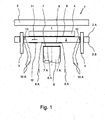
- Figure 1 is a schematic representation of a side view of a brake assembly according to the invention.
- the brake pad 1 has a support plate 2, which is held on the right and left in the figure by a guide device.
- the guide device on spars 3.
- the support plate 2 is slidably mounted on the spars 3.
- the carrier plate 2 has a front side 2A and a back side 2B. On the front side 2A, a friction lining 4 is applied, which can be pressed against a brake disk 5. Between the carrier plate 2 and the friction lining 4, an underlayer layer (not shown) may be provided.
- a brake piston 6, which can act on the support plate 2 with a piston-pressure surface 6A.
- the brake pad 1 is moved by the piston pressure on the bars 3 and pressed with the friction lining 4 against the brake disc 5.
- the pressing force of the friction lining 4 against the brake disk 5 can be detected by a plurality of functional layers 7, 8, 9 assigned to the brake pad 1, the functional layers being shown together only for reasons of illustration. In In practice, you will usually only choose one of the functional layers.
- the functional layer 7 is located on the piston pressure surface 6A of the brake piston 6 and is contacted via two electrically conductive wires 7A.
- the wires 7A are guided in the interior of the piston and thus protected from the environment.
- the force acting upon braking between the back side 2B of the support plate 2 and the piston pressure surface 6A causes a resistance change in the intermediate functional layer 7, which is detected via the wires 7A. From the change in resistance, the size of the force can be determined and thus optimize the braking process.
- the functional layer 7 remains even with an exchange of the brake pad on the piston 6 and saves a wiring of the brake pad, which would otherwise be solved in an exchange and reconnected.
- the functional layer 8 is also mounted between the back side 2B of the support plate 2 and the piston pressure surface 6A, directly on the back side 2B of the support plate 2.
- the functional layer 8 is contacted via two wires 8A.
- the change in resistance of this functional layer 8 is also dependent on the piston contact pressure.
- the functional layer 9 is arranged between the upper side 2A of the carrier plate 2 and the friction lining 4.
- the layer 9 is protected on both sides by the friction lining and the carrier plate 2. Electrical discharges, not shown, are guided on the upper side 2A of the carrier plate 2 along its rear side 2B.
- additional or alternative functional layers 10 are arranged.
- these layers are arranged in a region in which the carrier plate 2 comes into contact with the holders 3. In the illustrated embodiment, this is the inside of the spars 3 receiving openings in the carrier plate. It is also conceivable attachment to the spars 3 itself. Due to the change in resistance of the layers 10 are during a braking operation in the circumferential direction of the brake disc 5 and thus detected in the circumferential direction of the friction lining 4 acting forces. The circumferential force acting to the left in the plane of the drawing indicated by an arrow 11 presses the holder 3 against the left functional layer 10. The change in resistance of this layer is detected by two contacted wires 10A.
- another layer namely an exposed functional layer 12, is arranged in the vicinity of the functional layer 8 on the back side 2B of the carrier plate 2.
- the layer 12 is not exposed to the contact pressure of the piston.
- the change in resistance of this unloaded layer can be used either to determine a system temperature or, moreover, to correct the temperature component of the change in resistance of a loaded layer.
- the change in resistance of the layer occurring during braking is detected.
- the determined values are due to the temperature change.
- a compensation variable is determined which makes it possible to correct the determined resistance value of the layer 8 by a possible temperature component.
- each loaded and the unloaded layer have the same properties and dimensions. This facilitates the vote.
- a disc brake is shown in connection with the embodiment.
- the invention is applicable to, for example, a drum brake or a clutch.
- several pistons 6 are conceivable, each of which can carry a functional layer 7.
- FIG. 1 For better illustration. In fact, the invention is already applicable with a single layer. However, it is considered to be particularly advantageous to provide a functional layer in the direction of pressurization of the friction lining and a further layer in the circumferential direction, wherein the circumferential direction is understood to be essentially the direction transverse to the direction of pressurization.
- the holder of the support plate may vary. Only for example, a claw-like suspension of the support plate is called.
Landscapes
- Engineering & Computer Science (AREA)
- General Engineering & Computer Science (AREA)
- Mechanical Engineering (AREA)
- Braking Arrangements (AREA)
- Force Measurement Appropriate To Specific Purposes (AREA)
Claims (9)
- Procédé pour mesurer des forces appliquées à une garniture de friction (4) d'un patin de frein (1) d'un frein à disque ou à tambour ou d'un patin d'embrayage d'un embrayage, dans lequel au moins une couche fonctionnelle (7, 8, 9) est associée à la garniture de friction (4) comme composant intégral du patin de frein (1) ou selon le cas du patin d'embrayage, de telle façon qu'elle soit soumise aux forces appliquées à la garniture de friction (4), dans lequel la résistance électrique de cette au moins une couche fonctionnelle varie au moins dans une plage avec les forces agissant sur la garniture de friction, dans lequel la résistance électrique de cette au moins une couche fonctionnelle est mesurée et les forces sont déterminées à partir de la résistance mesurée.
- Procédé selon la revendication 1, caractérisé en ce que l'on détermine des forces de compression à partir de la résistance électrique.
- Procédé selon la revendication 1 ou 2, caractérisé en ce que l'on détermine des forces dans la direction périphérique de la garniture de friction.
- Procédé selon la revendication 2, caractérisé en ce que l'on mesure une autre résistance électrique d'une autre couche fonctionnelle (10) sollicitée de friction, dans lequel on détermine la part des forces en direction périphérique à partir de l'autre résistance électrique et dans lequel on corrige la force déterminée à partir de la résistance électrique de la couche fonctionnelle avec la part de force en direction périphérique.
- Procédé selon l'une quelconque des revendications 1 à 4, caractérisé en ce que l'on mesure une résistance électrique d'une couche fonctionnelle non sollicitée, dans lequel on détermine une part de température à partir de la résistance électrique de la couche fonctionnelle non sollicitée et dans lequel on corrige la force déterminée à partir de la résistance électrique de la couche fonctionnelle et/ou à partir de l'autre résistance électrique de l'autre couche fonctionnelle avec la part de température.
- Patin de frein d'un frein à disque ou à tambour ou patin d'embrayage, avec- une plaque de support (2),- une garniture de friction disposée sur la plaque de support, éventuellement avec interposition d'une sous-couche,- au moins une couche fonctionnelle associée à la plaque de support (2) pour mesurer des forces appliquées à la garniture de friction (4),dans lequel la couche fonctionnelle est disposée de telle façon qu'elle soit sollicitée par les forces agissant sur la garniture de friction (4),
dans lequel la couche fonctionnelle présente une résistance électrique, qui varie avec la force au moins dans une plage. - Patin de frein ou d'embrayage selon la revendication 6, caractérisé en ce que la couche fonctionnelle (9) est disposée sur la plaque de support (2) et/ou entre la sous-couche et la garniture de friction (4).
- Patin de frein ou d'embrayage selon la revendication 7, caractérisé en ce que la couche fonctionnelle s'étend sensiblement sur toute l'extension longitudinale de la garniture de friction (4).
- Patin de frein ou d'embrayage selon l'une quelconque des revendications 6 à 8, caractérisé en ce que la couche fonctionnelle est mise en contact par l'intermédiaire d'un câblage, dans lequel le câblage est détachable de préférence par une liaison par fiche.
Applications Claiming Priority (2)
| Application Number | Priority Date | Filing Date | Title |
|---|---|---|---|
| DE10259629A DE10259629B4 (de) | 2002-12-18 | 2002-12-18 | Brems-oder Kupplungsbelag mit integrierter Kraftmessung |
| DE10259629 | 2002-12-18 |
Publications (2)
| Publication Number | Publication Date |
|---|---|
| EP1431606A1 EP1431606A1 (fr) | 2004-06-23 |
| EP1431606B1 true EP1431606B1 (fr) | 2006-04-26 |
Family
ID=32336481
Family Applications (1)
| Application Number | Title | Priority Date | Filing Date |
|---|---|---|---|
| EP03027588A Expired - Lifetime EP1431606B1 (fr) | 2002-12-18 | 2003-12-02 | Patin de frein ou d'embrayage équipé d'un dispositif de mesure de force |
Country Status (3)
| Country | Link |
|---|---|
| EP (1) | EP1431606B1 (fr) |
| AT (1) | ATE324531T1 (fr) |
| DE (2) | DE10259629B4 (fr) |
Cited By (1)
| Publication number | Priority date | Publication date | Assignee | Title |
|---|---|---|---|---|
| WO2014170849A1 (fr) | 2013-04-17 | 2014-10-23 | Itt Manufacturing Enterprises Llc | Procédé et dispositif pour estimation en temps réel de la pression appliquée et du bruit dans un élément de frein, en particulier une plaquette de frein |
Families Citing this family (10)
| Publication number | Priority date | Publication date | Assignee | Title |
|---|---|---|---|---|
| DE102006053489B4 (de) * | 2006-11-14 | 2010-07-22 | Tmd Friction Services Gmbh | Brems- oder Kupplungsbelag mit kapazitivem Kraftsensor |
| ES2739897T3 (es) | 2014-09-08 | 2020-02-04 | Itt Italia Srl | Método para fabricar un elemento de frenado sensorizado, en particular una pastilla de freno y una pastilla de freno sensorizada obtenida de este modo |
| US9939035B2 (en) | 2015-05-28 | 2018-04-10 | Itt Italia S.R.L. | Smart braking devices, systems, and methods |
| ITUB20153709A1 (it) | 2015-09-17 | 2017-03-17 | Itt Italia Srl | Dispositivo di analisi e gestione dei dati generati da un sistema frenante sensorizzato per veicoli |
| ITUB20153706A1 (it) | 2015-09-17 | 2017-03-17 | Itt Italia Srl | Dispositivo frenante per veicolo pesante e metodo di prevenzione del surriscaldamento dei freni in un veicolo pesante |
| ITUA20161336A1 (it) | 2016-03-03 | 2017-09-03 | Itt Italia Srl | Dispositivo e metodo per il miglioramento delle prestazioni di un sistema antibloccaggio e antiscivolamento di un veicolo |
| IT201600077944A1 (it) | 2016-07-25 | 2018-01-25 | Itt Italia Srl | Dispositivo per il rilevamento della coppia residua di frenatura in un veicolo equipaggiato con freni a disco |
| IT201900015839A1 (it) | 2019-09-06 | 2021-03-06 | Itt Italia Srl | Pastiglia freno per veicoli e suo processo di produzione |
| IT202000013408A1 (it) | 2020-06-05 | 2021-12-05 | Itt Italia Srl | Pastiglia freno intelligente di veicolo e suo metodo di manifattura |
| CN117377603A (zh) | 2021-05-25 | 2024-01-09 | 意大利Itt有限责任公司 | 用于估计车辆的被制动元件和制动元件之间的残余扭矩的方法和装置 |
Family Cites Families (4)
| Publication number | Priority date | Publication date | Assignee | Title |
|---|---|---|---|---|
| DE3813494A1 (de) * | 1988-04-22 | 1989-11-09 | Bayerische Motoren Werke Ag | Vorrichtung zur temperaturbestimmung von periodisch bewegten kraftfahrzeug-teilen |
| DE29800635U1 (de) * | 1998-01-15 | 1998-03-05 | Sulzer Rüti AG, Rüti | Fangbremse für die Projektile einer Projektilwebmaschine |
| JP3760637B2 (ja) * | 1998-08-25 | 2006-03-29 | トヨタ自動車株式会社 | 車両用ブレーキのための電気制御装置 |
| EP1199491A1 (fr) * | 2000-10-17 | 2002-04-24 | Federal-Mogul Friction Products GmbH | Patin en matiére de friction avec capteur d'usure integré |
-
2002
- 2002-12-18 DE DE10259629A patent/DE10259629B4/de not_active Expired - Fee Related
-
2003
- 2003-12-02 AT AT03027588T patent/ATE324531T1/de not_active IP Right Cessation
- 2003-12-02 DE DE50303100T patent/DE50303100D1/de not_active Expired - Lifetime
- 2003-12-02 EP EP03027588A patent/EP1431606B1/fr not_active Expired - Lifetime
Cited By (2)
| Publication number | Priority date | Publication date | Assignee | Title |
|---|---|---|---|---|
| WO2014170849A1 (fr) | 2013-04-17 | 2014-10-23 | Itt Manufacturing Enterprises Llc | Procédé et dispositif pour estimation en temps réel de la pression appliquée et du bruit dans un élément de frein, en particulier une plaquette de frein |
| WO2014170726A1 (fr) | 2013-04-17 | 2014-10-23 | Itt Italia S.R.L. | Procédé de fabrication d'un élément de freinage avec détecteur intégré, en particulier une plaquette de frein, d'une plaquette de frein ayant un détecteur intégré, système de freinage de véhicule et procédé associé |
Also Published As
| Publication number | Publication date |
|---|---|
| DE10259629A1 (de) | 2004-07-15 |
| DE10259629B4 (de) | 2005-09-22 |
| DE50303100D1 (de) | 2006-06-01 |
| EP1431606A1 (fr) | 2004-06-23 |
| ATE324531T1 (de) | 2006-05-15 |
Similar Documents
| Publication | Publication Date | Title |
|---|---|---|
| EP2057386B1 (fr) | Capteur de temperature et d'usure pour systemes de freinage ou d'embrayage | |
| DE3590038C2 (fr) | ||
| EP2687823B2 (fr) | Dispositif destiné à l'enregistrement et au traitement de valeurs de mesure de capteur et/ou à la commande d'actionneurs | |
| EP1923592B1 (fr) | Garniture de frein ou d'embrayage équipé d'un capteur capacitif de forces | |
| AT524872B1 (de) | Vorrichtung zum Erfassen der Zuspannkräfte zwischen einem Bremskörper und einem Bremsrotor einer Scheiben- oder Trommelbremse | |
| DE10259629B4 (de) | Brems-oder Kupplungsbelag mit integrierter Kraftmessung | |
| WO2008071578A1 (fr) | Enregistrement séparé des forces d'application et de friction sur un frein | |
| DE102012007471A1 (de) | Messanordnung zur Zuspannkraftmessung einer Scheibenbremse und eine entsprechende Scheibenbremse | |
| DE102006015034B4 (de) | Verfahren und Recheneinheit zur Bestimmung eines Leistungsparameters einer Bremse | |
| WO2005015045A1 (fr) | Frein pour vehicule | |
| EP3377377B1 (fr) | Agencement, dispositif avec un tel agencement, frein à disque avec un tel agencement et procédé avec un tel agencement de mesurer un deplacement generée par un force de freinage | |
| DE102019120586A1 (de) | Sensorhalter, Sensoranordnung, Messanordnung und Verfahren zum Messen eines Druckstückspiels in einem Zahnstangenlenkgetriebe | |
| DE8326488U1 (de) | Kraft- bzw. druckmessgeber | |
| DE102008025287A1 (de) | Vorrichtung zur Messung von Pressungskenngrößen im Spalt zwischen zylindrischen Körpern | |
| DE10331603B4 (de) | Vorrichtung mit aufeinander abrollenden Zylindern mit wenigstens einem Sensor und ein Verfahren zur Messung eines Verschleißes von Schmitzringen | |
| DE3531245A1 (de) | Vorrichtung zum messen der achslast von fahrzeugen | |
| EP1259377A1 (fr) | Dispositif de raclage pour le nettoyage d'un cylindre rotatif | |
| DE19601077A1 (de) | Kraftsensor | |
| DE3348387C2 (en) | Vehicle brakes testing system | |
| DE4233867C2 (de) | Vorrichtung zum Messen des Auflagedruckes einer Greifereinrichtung in einer Bogenrotationsdruckmaschine | |
| AT526520B1 (de) | Vorrichtung zum Erfassen der Druckkräfte zwischen zwei Körpern | |
| AT525992B1 (de) | Vorrichtung zum Erfassen der Druckkräfte zwischen zwei unter Krafteinwirkung aneinander anstellbaren Körpern | |
| CH695168A5 (de) | Vorrichtung zur Messung des Anpressdrucks eines an einer Walze angelegten Schabers. | |
| DE102012012222A1 (de) | Messsystem zur dynamischen Erfassung von Kräften | |
| DE10348829A1 (de) | Kraftfahrzeugbremse |
Legal Events
| Date | Code | Title | Description |
|---|---|---|---|
| PUAI | Public reference made under article 153(3) epc to a published international application that has entered the european phase |
Free format text: ORIGINAL CODE: 0009012 |
|
| AK | Designated contracting states |
Kind code of ref document: A1 Designated state(s): AT BE BG CH CY CZ DE DK EE ES FI FR GB GR HU IE IT LI LU MC NL PT RO SE SI SK TR |
|
| AX | Request for extension of the european patent |
Extension state: AL LT LV MK |
|
| 17P | Request for examination filed |
Effective date: 20041210 |
|
| AKX | Designation fees paid |
Designated state(s): AT BE BG CH CY CZ DE DK EE ES FI FR GB GR HU IE IT LI LU MC NL PT RO SE SI SK TR |
|
| 17Q | First examination report despatched |
Effective date: 20050518 |
|
| GRAP | Despatch of communication of intention to grant a patent |
Free format text: ORIGINAL CODE: EPIDOSNIGR1 |
|
| RAP1 | Party data changed (applicant data changed or rights of an application transferred) |
Owner name: TMD FRICTION SERVICES GMBH |
|
| GRAS | Grant fee paid |
Free format text: ORIGINAL CODE: EPIDOSNIGR3 |
|
| GRAA | (expected) grant |
Free format text: ORIGINAL CODE: 0009210 |
|
| AK | Designated contracting states |
Kind code of ref document: B1 Designated state(s): AT BE BG CH CY CZ DE DK EE ES FI FR GB GR HU IE IT LI LU MC NL PT RO SE SI SK TR |
|
| PG25 | Lapsed in a contracting state [announced via postgrant information from national office to epo] |
Ref country code: IT Free format text: LAPSE BECAUSE OF FAILURE TO SUBMIT A TRANSLATION OF THE DESCRIPTION OR TO PAY THE FEE WITHIN THE PRESCRIBED TIME-LIMIT;WARNING: LAPSES OF ITALIAN PATENTS WITH EFFECTIVE DATE BEFORE 2007 MAY HAVE OCCURRED AT ANY TIME BEFORE 2007. THE CORRECT EFFECTIVE DATE MAY BE DIFFERENT FROM THE ONE RECORDED. Effective date: 20060426 Ref country code: CZ Free format text: LAPSE BECAUSE OF FAILURE TO SUBMIT A TRANSLATION OF THE DESCRIPTION OR TO PAY THE FEE WITHIN THE PRESCRIBED TIME-LIMIT Effective date: 20060426 Ref country code: SK Free format text: LAPSE BECAUSE OF FAILURE TO SUBMIT A TRANSLATION OF THE DESCRIPTION OR TO PAY THE FEE WITHIN THE PRESCRIBED TIME-LIMIT Effective date: 20060426 Ref country code: FI Free format text: LAPSE BECAUSE OF FAILURE TO SUBMIT A TRANSLATION OF THE DESCRIPTION OR TO PAY THE FEE WITHIN THE PRESCRIBED TIME-LIMIT Effective date: 20060426 Ref country code: SI Free format text: LAPSE BECAUSE OF FAILURE TO SUBMIT A TRANSLATION OF THE DESCRIPTION OR TO PAY THE FEE WITHIN THE PRESCRIBED TIME-LIMIT Effective date: 20060426 Ref country code: RO Free format text: LAPSE BECAUSE OF FAILURE TO SUBMIT A TRANSLATION OF THE DESCRIPTION OR TO PAY THE FEE WITHIN THE PRESCRIBED TIME-LIMIT Effective date: 20060426 Ref country code: NL Free format text: LAPSE BECAUSE OF FAILURE TO SUBMIT A TRANSLATION OF THE DESCRIPTION OR TO PAY THE FEE WITHIN THE PRESCRIBED TIME-LIMIT Effective date: 20060426 Ref country code: IE Free format text: LAPSE BECAUSE OF FAILURE TO SUBMIT A TRANSLATION OF THE DESCRIPTION OR TO PAY THE FEE WITHIN THE PRESCRIBED TIME-LIMIT Effective date: 20060426 |
|
| REG | Reference to a national code |
Ref country code: GB Ref legal event code: FG4D Free format text: NOT ENGLISH |
|
| REG | Reference to a national code |
Ref country code: IE Ref legal event code: FG4D Free format text: LANGUAGE OF EP DOCUMENT: GERMAN |
|
| REF | Corresponds to: |
Ref document number: 50303100 Country of ref document: DE Date of ref document: 20060601 Kind code of ref document: P |
|
| PG25 | Lapsed in a contracting state [announced via postgrant information from national office to epo] |
Ref country code: SE Free format text: LAPSE BECAUSE OF FAILURE TO SUBMIT A TRANSLATION OF THE DESCRIPTION OR TO PAY THE FEE WITHIN THE PRESCRIBED TIME-LIMIT Effective date: 20060726 Ref country code: DK Free format text: LAPSE BECAUSE OF FAILURE TO SUBMIT A TRANSLATION OF THE DESCRIPTION OR TO PAY THE FEE WITHIN THE PRESCRIBED TIME-LIMIT Effective date: 20060726 |
|
| PG25 | Lapsed in a contracting state [announced via postgrant information from national office to epo] |
Ref country code: ES Free format text: LAPSE BECAUSE OF FAILURE TO SUBMIT A TRANSLATION OF THE DESCRIPTION OR TO PAY THE FEE WITHIN THE PRESCRIBED TIME-LIMIT Effective date: 20060806 |
|
| GBT | Gb: translation of ep patent filed (gb section 77(6)(a)/1977) |
Effective date: 20060814 |
|
| PG25 | Lapsed in a contracting state [announced via postgrant information from national office to epo] |
Ref country code: PT Free format text: LAPSE BECAUSE OF FAILURE TO SUBMIT A TRANSLATION OF THE DESCRIPTION OR TO PAY THE FEE WITHIN THE PRESCRIBED TIME-LIMIT Effective date: 20060926 |
|
| ET | Fr: translation filed | ||
| NLV1 | Nl: lapsed or annulled due to failure to fulfill the requirements of art. 29p and 29m of the patents act | ||
| REG | Reference to a national code |
Ref country code: IE Ref legal event code: FD4D |
|
| PG25 | Lapsed in a contracting state [announced via postgrant information from national office to epo] |
Ref country code: BE Free format text: LAPSE BECAUSE OF NON-PAYMENT OF DUE FEES Effective date: 20061231 Ref country code: MC Free format text: LAPSE BECAUSE OF NON-PAYMENT OF DUE FEES Effective date: 20061231 |
|
| PLBE | No opposition filed within time limit |
Free format text: ORIGINAL CODE: 0009261 |
|
| STAA | Information on the status of an ep patent application or granted ep patent |
Free format text: STATUS: NO OPPOSITION FILED WITHIN TIME LIMIT |
|
| 26N | No opposition filed |
Effective date: 20070129 |
|
| BERE | Be: lapsed |
Owner name: TMD FRICTION SERVICES G.M.B.H. Effective date: 20061231 |
|
| PG25 | Lapsed in a contracting state [announced via postgrant information from national office to epo] |
Ref country code: AT Free format text: LAPSE BECAUSE OF NON-PAYMENT OF DUE FEES Effective date: 20061202 |
|
| PG25 | Lapsed in a contracting state [announced via postgrant information from national office to epo] |
Ref country code: GR Free format text: LAPSE BECAUSE OF FAILURE TO SUBMIT A TRANSLATION OF THE DESCRIPTION OR TO PAY THE FEE WITHIN THE PRESCRIBED TIME-LIMIT Effective date: 20060727 |
|
| PG25 | Lapsed in a contracting state [announced via postgrant information from national office to epo] |
Ref country code: EE Free format text: LAPSE BECAUSE OF FAILURE TO SUBMIT A TRANSLATION OF THE DESCRIPTION OR TO PAY THE FEE WITHIN THE PRESCRIBED TIME-LIMIT Effective date: 20060426 Ref country code: BG Free format text: LAPSE BECAUSE OF FAILURE TO SUBMIT A TRANSLATION OF THE DESCRIPTION OR TO PAY THE FEE WITHIN THE PRESCRIBED TIME-LIMIT Effective date: 20060726 |
|
| PG25 | Lapsed in a contracting state [announced via postgrant information from national office to epo] |
Ref country code: LU Free format text: LAPSE BECAUSE OF NON-PAYMENT OF DUE FEES Effective date: 20061202 Ref country code: TR Free format text: LAPSE BECAUSE OF FAILURE TO SUBMIT A TRANSLATION OF THE DESCRIPTION OR TO PAY THE FEE WITHIN THE PRESCRIBED TIME-LIMIT Effective date: 20060426 Ref country code: HU Free format text: LAPSE BECAUSE OF FAILURE TO SUBMIT A TRANSLATION OF THE DESCRIPTION OR TO PAY THE FEE WITHIN THE PRESCRIBED TIME-LIMIT Effective date: 20061027 |
|
| REG | Reference to a national code |
Ref country code: CH Ref legal event code: PL |
|
| PG25 | Lapsed in a contracting state [announced via postgrant information from national office to epo] |
Ref country code: LI Free format text: LAPSE BECAUSE OF NON-PAYMENT OF DUE FEES Effective date: 20071231 Ref country code: CH Free format text: LAPSE BECAUSE OF NON-PAYMENT OF DUE FEES Effective date: 20071231 |
|
| PG25 | Lapsed in a contracting state [announced via postgrant information from national office to epo] |
Ref country code: CY Free format text: LAPSE BECAUSE OF FAILURE TO SUBMIT A TRANSLATION OF THE DESCRIPTION OR TO PAY THE FEE WITHIN THE PRESCRIBED TIME-LIMIT Effective date: 20060426 |
|
| REG | Reference to a national code |
Ref country code: FR Ref legal event code: PLFP Year of fee payment: 13 |
|
| REG | Reference to a national code |
Ref country code: FR Ref legal event code: PLFP Year of fee payment: 14 |
|
| REG | Reference to a national code |
Ref country code: FR Ref legal event code: PLFP Year of fee payment: 15 |
|
| PGFP | Annual fee paid to national office [announced via postgrant information from national office to epo] |
Ref country code: DE Payment date: 20191231 Year of fee payment: 17 |
|
| PGFP | Annual fee paid to national office [announced via postgrant information from national office to epo] |
Ref country code: FR Payment date: 20191219 Year of fee payment: 17 |
|
| PGFP | Annual fee paid to national office [announced via postgrant information from national office to epo] |
Ref country code: GB Payment date: 20191220 Year of fee payment: 17 |
|
| REG | Reference to a national code |
Ref country code: DE Ref legal event code: R119 Ref document number: 50303100 Country of ref document: DE |
|
| GBPC | Gb: european patent ceased through non-payment of renewal fee |
Effective date: 20201202 |
|
| PG25 | Lapsed in a contracting state [announced via postgrant information from national office to epo] |
Ref country code: FR Free format text: LAPSE BECAUSE OF NON-PAYMENT OF DUE FEES Effective date: 20201231 |
|
| PG25 | Lapsed in a contracting state [announced via postgrant information from national office to epo] |
Ref country code: GB Free format text: LAPSE BECAUSE OF NON-PAYMENT OF DUE FEES Effective date: 20201202 Ref country code: DE Free format text: LAPSE BECAUSE OF NON-PAYMENT OF DUE FEES Effective date: 20210701 |