EP1431666A1 - Système de montage pour poêle reposant sur le sol et poêle reposant sur le sol - Google Patents
Système de montage pour poêle reposant sur le sol et poêle reposant sur le sol Download PDFInfo
- Publication number
- EP1431666A1 EP1431666A1 EP03026704A EP03026704A EP1431666A1 EP 1431666 A1 EP1431666 A1 EP 1431666A1 EP 03026704 A EP03026704 A EP 03026704A EP 03026704 A EP03026704 A EP 03026704A EP 1431666 A1 EP1431666 A1 EP 1431666A1
- Authority
- EP
- European Patent Office
- Prior art keywords
- module
- combustion chamber
- train
- heating gas
- smoke
- Prior art date
- Legal status (The legal status is an assumption and is not a legal conclusion. Google has not performed a legal analysis and makes no representation as to the accuracy of the status listed.)
- Granted
Links
- 238000002485 combustion reaction Methods 0.000 claims abstract description 59
- 239000002184 metal Substances 0.000 claims abstract description 4
- 229910045601 alloy Inorganic materials 0.000 claims abstract description 3
- 239000000956 alloy Substances 0.000 claims abstract description 3
- 239000010970 precious metal Substances 0.000 claims abstract description 3
- 239000003570 air Substances 0.000 claims description 61
- 238000010438 heat treatment Methods 0.000 claims description 54
- 238000010276 construction Methods 0.000 claims description 27
- 238000007789 sealing Methods 0.000 claims description 16
- 230000007704 transition Effects 0.000 claims description 12
- 239000012080 ambient air Substances 0.000 claims description 4
- 238000005338 heat storage Methods 0.000 claims description 3
- 239000011449 brick Substances 0.000 claims description 2
- 239000007789 gas Substances 0.000 abstract description 48
- 239000003546 flue gas Substances 0.000 abstract description 7
- UGFAIRIUMAVXCW-UHFFFAOYSA-N Carbon monoxide Chemical compound [O+]#[C-] UGFAIRIUMAVXCW-UHFFFAOYSA-N 0.000 abstract description 6
- 238000000605 extraction Methods 0.000 abstract 2
- 239000000567 combustion gas Substances 0.000 description 12
- 238000007689 inspection Methods 0.000 description 8
- 238000005192 partition Methods 0.000 description 5
- 239000002023 wood Substances 0.000 description 5
- 229910000831 Steel Inorganic materials 0.000 description 4
- 238000009434 installation Methods 0.000 description 4
- 239000000463 material Substances 0.000 description 4
- 239000010959 steel Substances 0.000 description 4
- 239000000919 ceramic Substances 0.000 description 3
- 239000000446 fuel Substances 0.000 description 3
- 239000000779 smoke Substances 0.000 description 3
- 238000009423 ventilation Methods 0.000 description 3
- 239000004570 mortar (masonry) Substances 0.000 description 2
- 239000000853 adhesive Substances 0.000 description 1
- 239000004020 conductor Substances 0.000 description 1
- 238000005553 drilling Methods 0.000 description 1
- 230000000694 effects Effects 0.000 description 1
- 238000010304 firing Methods 0.000 description 1
- 238000009413 insulation Methods 0.000 description 1
- 238000004519 manufacturing process Methods 0.000 description 1
- 239000007769 metal material Substances 0.000 description 1
- 239000002245 particle Substances 0.000 description 1
- 238000011084 recovery Methods 0.000 description 1
- 230000000630 rising effect Effects 0.000 description 1
- 238000000926 separation method Methods 0.000 description 1
- 239000004071 soot Substances 0.000 description 1
- 239000010935 stainless steel Substances 0.000 description 1
- 229910001220 stainless steel Inorganic materials 0.000 description 1
- 238000003466 welding Methods 0.000 description 1
Images

Classifications
-
- F—MECHANICAL ENGINEERING; LIGHTING; HEATING; WEAPONS; BLASTING
- F24—HEATING; RANGES; VENTILATING
- F24B—DOMESTIC STOVES OR RANGES FOR SOLID FUELS; IMPLEMENTS FOR USE IN CONNECTION WITH STOVES OR RANGES
- F24B1/00—Stoves or ranges
- F24B1/02—Closed stoves
- F24B1/022—Closed stoves easily collapsible or easily removable
Definitions
- the invention relates to a construction system for a basic furnace with supply air, a combustion chamber and a heating gas flue as well as a basic furnace such a construction system.
- Such basic ovens are also known in modular design, such as known from DE 83 00 138.8 U1 or DE 84 06 321 U1.
- This Basic stoves consist of ceramic and / or chamotte molded parts. however there is also the problem with these basic furnaces that due to the Operation occurring temperature fluctuations and related Expansions and cracks occur in the basic furnaces in the Supported flue gas channels combustion gases, for example due to a slight negative pressure in the living space through a ventilation system can escape into the living space.
- DE 84 06 321 U1 also a conventional post-heating box made of sheet steel at the smoke outlet of the basic furnace can be connected. However, this post-heating box is a convective heating element that allows a flow of warm air to heat others Spaces is created.
- the supply air duct, combustion chamber and heating gas flue are smoke-tight are, the supply air is independent of the room air and at least the Combustion chamber and the heating gas flue from a heat-resistant and heat-conducting Material is an operation independent of the ambient air Guaranteed fireplace.
- At least the combustion chamber and the heating gas flue consists of gas-tight elements made of metal, precious metal or alloys thereof, in particular in the form of steel sheets or Stainless steel sheets.
- the construction system forms the inner one that is independent of the ambient air Air supply system, fuel combustion and Removal of the heating gases.
- Made from sheet metal Components can also with large temperature fluctuations, as in Furnaces occur, are permanently made smoke-tight, since the metallic materials in contrast to ceramic and / or chamotte molded parts respond with sufficient elasticity to thermal loads.
- the outside of the construction system with firebricks and / or soapstone.
- the are preferred Firebricks, ceramic elements and / or soapstones only loose around the construction system joined together. The heat emission thus corresponds conventional basic ovens to the outside, whereas the construction system forms a permanent smoke-tight additional inner shell.
- a supply air module for the supply air duct, a combustion chamber module for the combustion chamber and at least one train module for the heating gas train are a logical separation of the various functions of the basic furnace considered in the body system.
- the supply air module receives a tight one Connection to an air supply pipe that expels air at atmospheric pressure outside of the building.
- the combustion chamber module receives a connection to the supply air module and contains one Firebox flap for feeding the fuel, especially wood.
- the Train module which can also be formed in several parts, is to the Firing chamber module attached and directs the combustion gases to Chimney that also flowed smoke-tight to the last one Train module is connected.
- the entire air or Heating gas routing should be tight.
- Flanges with sealing surfaces preferably additionally with or sealing tapes to be glued on, intended for smoke-tight screwing.
- the transition flanges are preferred over the module dimensions tapered, but the transitions are adequate Have a cross section for the flue gas duct. By the tapered Design of the flange, the sealing surface dimension is reduced so far that manufacturing tolerances and uneven stresses are no problem be taken up by the flanges.
- the combustion chamber module is a combustion chamber door with a smoke-tight closing device on.
- the locking device ensures that the firebox door automatically, for example acted upon by spring force, closes, ie one open combustion chamber door is avoided, as with the combustion chamber door open due to the low negative pressure in the living room, smoke gases in the living room can pull.
- the firebox door closing device is preferred equipped with an automatic lock according to DE 101 01 246 C1, with which a permanently smoke-tight fire door even with larger ones Differential pressure between living space and combustion chamber is guaranteed.
- the train module has a gas duct due to its large longitudinal extension of the module and / or angled arrangement in the train module a long Heating gas path is the most effective use of the in the Combustion gases used thermal energy for heating purposes.
- the train modules are adapted to the required heating output Mass of refractory bricks and / or soapstones.
- the inspection opening can preferably have a circular shape and have a screw cap, the opening width for one manual intervention and to insert a vacuum cleaner should suffice.
- the supply air module is preferably below and a first train module above the Combustion chamber module arranged. This is usually from below by an im Outside air supplied to the screed pipeline with a sealing connection directed into the supply air module and from there to the combustion chamber in the combustion chamber module fed.
- the combustion gases rising upwards in the combustion chamber are necessarily in the first train module above directed. Partitions for angled guidance are preferred in the train module of the heating gas arranged.
- Additional train modules can be arranged above the first train module be their heating gases at defined transfer points Deliver smoke-tight to the train module above. That in the direction of flue gas flow last train module then contains a transition piece for smoke-gas-tight transfer of the heating gases into the chimney.
- module provided that extends over the entire height of the basic furnace extends. This allows a more structured and thus aesthetic, outer shape can be achieved with very long heating gas paths.
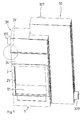
- Fig. 1 shows a three-dimensional view of a system for a basic furnace in a first embodiment.
- the construction system consists of four Steel sheet manufactured modules, namely a supply air module 1, a Combustion chamber module 2 and two train modules 31 and 32.
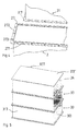
- the supply air module 1 is in the exemplary embodiment shown, in particular 3 shows the exploded view, trough-shaped.
- the underside forms a rectangular base plate 11, on the four plates (back and side surfaces) 12, 13 are welded vertically and the cuboid Form the tub.
- a supply air opening 14 is arranged with an attachment piece 15.
- a connecting flange 16 is provided in the form of a trough.
- the combustion chamber module 2 has a connection flange on its underside 16 of the supply air module 1 matching connecting flange 26. Overall the combustion chamber module 2 is designed as a cuboid shape open at the top, wherein the underside of the combustion chamber module 2 forms a combustion chamber floor 21 which openings for supply suitable for optimal combustion of fresh air from the supply air module 1. On the firebox floor 21 are two closed side walls 22, one closed Rear wall 23 and a front plate 24 constructed. In the front panel 24 is an opening 25 with a mounting flange for attaching a combustion chamber door spared. 1 to 3, the combustion chamber door is not shown. At the Opening 25 with a mounting flange can be, for example, a rotating fire door with automatically locking door locking device according to DE 101 01 246 C1 can be attached.
- the upper edge of the combustion chamber module 2 in turn has a connecting flange 27 on which a cuboid first train module 31 can be placed is.
- the first pull module 31 has one for the connecting flange 27 of the combustion chamber module 2 matching connecting flange 317.
- the cuboid first train module 31 is essentially closed educated.
- a base plate 311 is located on its underside an opening 312 for introducing the combustion gases from below arranged combustion chamber module 2.
- On the base plate 311 are a closed front and rear walls 313, 313, a left side wall 314 and a right side wall 316 arranged.
- In the left side wall 314 is a circular inspection opening 315 with a screw cap.
- the right side wall 316 has an opening 319 with a Connection flange 318 for forwarding the heating gases.
- a baffle 310 is used to a to get angled and therefore longer heating gas path.
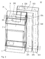
- the second train module 32 is essentially L-shaped, with the long one Leg two heating gas channels 321, 322 separated by a partition 320 and another in the short leg to the second heating gas channel 322 subsequent third heating gas channel 323 are arranged.
- To the connecting flange 318 of the first pull module 31 is in the area of the inner bend of the L-shaped one second tension module 32 a matching connecting flange 328 arranged.
- In the train module wall there is one in the first heating gas duct 321 leading opening 324 arranged.
- lower end of the heating gas channel 321 is in the partition 320 Opening 325 provided that the heating gases from the first heating gas channel 321 in conduct the second heating gas channel 322.
- the second hot gas channel 322 goes directly into the third heating gas channel 323.
- At the end of the third Hot gas channel 323 is a rearward opening 326 with a Stub 327 arranged.
- At the lower end of the L-shaped second train module 32 is an inspection opening 329 also with a smoke-tight Screw lid provided.
- FIG. 4 shows a detailed spatial view of a flange connection.
- the detailed view shown in FIG. 4 shows the flange connection between combustion chamber module 2 and first train module 31, as in FIG. 1 with IV characterized.
- the flange connections of the other module transitions are designed accordingly.
- FIG. 4 the upper part of the combustion chamber module 2 is cut out below shown.
- a lower section of the first train module 31 is above it Cutout shown.
- the combustion chamber module 2 has on its upper edge a connecting flange 27, the upper edge of which is a horizontal sealing surface 271 forms.
- a plurality of bores 273 for screw connection with the corresponding connection flange 317 of the first train module 31 is provided.
- the assembly system shown in Fig. 1 in the assembled state is thus after a tight connection of the fresh air supply independent of room air on Supply air module 1 at the nozzle 15 there and smoke-tight connection of the Stutzen 327 on the chimney completely from the living room atmosphere decoupled.
- the combustion in the combustion chamber module 2 thus takes place completely direct vent. Even if there is one in the living room low negative pressure compared to the pressure conditions in the body system no flue gases can get into the living space.
- the exemplary embodiment is in Fig. 2 in a wireframe representation of the heating gas path X shown in dashed line with flow direction (arrow).
- Wood forms combustion or heating gases from the combustion chamber module via the opening 312 in the module transition with the flange connection 27, 317 into the first train module 31 and there around the guide plate 310 Flow left around to the opening 319 on the connecting flange 318, where the Heating gases into the second train module 32 through the opening 324 in the first Enter heating gas duct 321, there up to opening 325 in partition 320 flow down and in the second heating gas channel 322 and subsequent third Flow the heating gas channel 323 up to the opening 326 in order to flow in via the connection 327 to get the chimney, not shown.
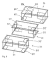
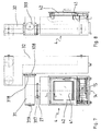
- FIG. 5 is a spatial view of a train module 3 in another Embodiment shown. To describe the first embodiment functionally identical components have the same reference numerals designated.
- the train module 3 consists of three, essentially arranged one above the other equally trained modules.
- the three combined in train module 3 The heating gases flow through the modules from bottom to top.
- Pass-through module 33 called. That in the direction of flow Combustion gases last flow train module is called the final train module 34 designated.
- the cuboidal train modules 33, 34 have a base plate 311 with two openings 312 arranged on a long side near the two corners. On this base plate 311 there are four in the through train modules 33 closed walls 313 welded on.
- baffles 310 To the way of the smoke gases between the openings 312, 312 'to extend, are baffles 310 intended.
- When the through train modules 33 are placed one on top of the other the next following module is rotated by 180 ° around its vertical axis placed.
- the respective openings 312, 312 'thus correspond. to each other to ensure proper flue gas discharge.
- the final train module 34 differs in that the top of the Module is designed as a completely closed cover plate 311 '. At the The rear wall 313 'of the final train module 34, however, is an opening 326 arranged with a connector 327 for connection to the chimney. The Opening 326 is opposite openings 312 in base plate 311 oriented. Baffles 310 are also provided in the final train module 34 Extension of the heating gas path provided.
- Fig. 7 is designed as a combined supply air and combustion chamber module 4 Module shown.
- the supply air and combustion chamber module 4 has a Stub 15 formed supply air opening 14 for connecting the room air independent Supply air routing.
- the upper part of the supply air and combustion chamber module 4 includes the combustion chamber 41, which closes automatically trained firebox door 42 with automatic firebox door lock Is provided.
- the firebox door 42 is in the locked closed position smoke-tight design.
- a first train module 31 is located above the supply air and combustion chamber module 4 via a connecting flange that is very tapered in cross-section compared to the module 27 or 317 with one inserted between the sealing surfaces Seal shown.
- the first train module 31 has an inspection opening 319, as also shown in FIG. 8 in a side view.
- the first train module 31 is connected downstream of the flue gas duct a second train module 32 via a flange connection 318, 328.
- the second train module 32 essentially has the view according to FIG. 7 vertically extending, inverted L-shape. It is equipped similarly as the second train module 32 according to the first embodiment, see in particular Fig. 2 and associated description.
- the required modules For the local conditions at the installation site of the basic furnace first selected the required modules. In particular, the heating gas path formed by the train modules to the desired heating behavior of the basic furnace. The required modules will then be delivered individually and assembled on site starting with the supply air module 1. It is on a gas-tight connection of the supply air nozzle 1 5 in Building provided air supply pipe respected. On the connecting flange 16 a sealing tape is placed and the combustion chamber module 2 with its Connection flange 26 attached and screwed gas-tight. following the required train modules 3 are also inserted by Sealing tapes mounted on their flange connections and from the last one Train module a smoke-tight connection by means of connector 327 to the Chimney created.
- prefabricated chamotte or soapstones are loosely in the Area of the combustion chamber module 2 and the train modules 3 on its sheet steel surface created. Through choice of material and material thickness it will Heat storage behavior influenced and tailored to the specifications.
- an outer shell made of stove tiles, Soapstone or chamotte plates set.
- the blocks are included well-known special mortar built into a stable outer shell. Between the building system covered with firebrick or soapstone and the outer shell is left an air gap, the only serves as an expansion buffer and not for air circulation.
- This double-shell construction also ensures that the Front plate 24 of the combustion chamber module 2 arranged through the combustion chamber door Extends through the outer shell and is bordered there.
- the inspection openings are also 325, 329 designed so that external access is possible.
Landscapes
- Engineering & Computer Science (AREA)
- Chemical & Material Sciences (AREA)
- Combustion & Propulsion (AREA)
- Mechanical Engineering (AREA)
- General Engineering & Computer Science (AREA)
- Tunnel Furnaces (AREA)
- Solid-Fuel Combustion (AREA)
- Incineration Of Waste (AREA)
- Conveying And Assembling Of Building Elements In Situ (AREA)
- Load-Engaging Elements For Cranes (AREA)
- Buildings Adapted To Withstand Abnormal External Influences (AREA)
- Waste-Gas Treatment And Other Accessory Devices For Furnaces (AREA)
Priority Applications (2)
| Application Number | Priority Date | Filing Date | Title |
|---|---|---|---|
| DE20320384U DE20320384U1 (de) | 2002-12-17 | 2003-11-21 | Aufbausystem für einen Grundofen sowie Grundofen |
| SI200330673T SI1431666T1 (sl) | 2002-12-17 | 2003-11-21 | Samostojeca pec z montaznim sistemom |
Applications Claiming Priority (2)
| Application Number | Priority Date | Filing Date | Title |
|---|---|---|---|
| DE10258888A DE10258888B4 (de) | 2002-12-17 | 2002-12-17 | Aufbausystem für einen Grundofen sowie Grundofen |
| DE10258888 | 2002-12-17 |
Publications (2)
| Publication Number | Publication Date |
|---|---|
| EP1431666A1 true EP1431666A1 (fr) | 2004-06-23 |
| EP1431666B1 EP1431666B1 (fr) | 2006-11-29 |
Family
ID=32336389
Family Applications (1)
| Application Number | Title | Priority Date | Filing Date |
|---|---|---|---|
| EP03026704A Expired - Lifetime EP1431666B1 (fr) | 2002-12-17 | 2003-11-21 | Poêle reposant sur le sol avec système de montage |
Country Status (5)
| Country | Link |
|---|---|
| EP (1) | EP1431666B1 (fr) |
| AT (1) | ATE347073T1 (fr) |
| DE (2) | DE10258888B4 (fr) |
| DK (1) | DK1431666T3 (fr) |
| ES (1) | ES2275994T3 (fr) |
Cited By (2)
| Publication number | Priority date | Publication date | Assignee | Title |
|---|---|---|---|---|
| EP2149753A3 (fr) * | 2008-07-28 | 2012-02-22 | Mertens- Kachelöfen und Fliesen GmbH | Four à combustible solide |
| IT201900007392A1 (it) * | 2019-05-28 | 2020-11-28 | Ungaro Srl | Stufa a biomassa in particelle, munito di sistema di pulizia facilitato |
Families Citing this family (3)
| Publication number | Priority date | Publication date | Assignee | Title |
|---|---|---|---|---|
| DE202008008855U1 (de) | 2008-10-01 | 2009-05-20 | Clama Holding Gmbh | Beheizungsanordnung mit Belüftungsanlage und Verbrennungsofen |
| DE202009004942U1 (de) | 2009-06-19 | 2009-08-20 | Mertens-Kachelöfen und Fliesen GmbH | Grundofenanordnung mit einem Wärmetauscher |
| DE102009033577A1 (de) * | 2009-07-16 | 2011-01-20 | Kai Dumslaff | Ofen und Ofenbausatz für Festbrennstoffe |
Citations (5)
| Publication number | Priority date | Publication date | Assignee | Title |
|---|---|---|---|---|
| DE8300138U1 (de) | 1983-01-05 | 1983-10-27 | Zakrzewski, Edmund, 6685 Schiffweiler | Mini-Kabelbox mit automatischer Kabelrückspulung und Rücklaufsperre |
| FR2682741A1 (fr) * | 1991-07-19 | 1993-04-23 | Aeiep | Incinerateur de dechets menagers transportable. |
| DE8406321U1 (de) | 1984-03-01 | 1994-02-17 | Söldner, Konrad, 92353 Postbauer-Heng | Aus Feuerfestmassen hergestellter Ofen in Bauteilen |
| WO2001094850A1 (fr) * | 2000-06-09 | 2001-12-13 | Nordisk Miljöenergi I Norr Ab | Poele de chauffage |
| DE10101246C1 (de) | 2001-01-12 | 2002-07-11 | Deckert Maschb Gmbh | Feuerraumtürschließeinrichtung |
Family Cites Families (1)
| Publication number | Priority date | Publication date | Assignee | Title |
|---|---|---|---|---|
| DE8300132U1 (de) * | 1983-01-05 | 1983-06-16 | Heika Kachel und Ofen Handelsgesellschaft mbH, 8501 Schwarzenbruck | Grundofen |
-
2002
- 2002-12-17 DE DE10258888A patent/DE10258888B4/de not_active Expired - Fee Related
-
2003
- 2003-11-21 AT AT03026704T patent/ATE347073T1/de active
- 2003-11-21 DE DE50305829T patent/DE50305829D1/de not_active Expired - Lifetime
- 2003-11-21 DK DK03026704T patent/DK1431666T3/da active
- 2003-11-21 EP EP03026704A patent/EP1431666B1/fr not_active Expired - Lifetime
- 2003-11-21 ES ES03026704T patent/ES2275994T3/es not_active Expired - Lifetime
Patent Citations (5)
| Publication number | Priority date | Publication date | Assignee | Title |
|---|---|---|---|---|
| DE8300138U1 (de) | 1983-01-05 | 1983-10-27 | Zakrzewski, Edmund, 6685 Schiffweiler | Mini-Kabelbox mit automatischer Kabelrückspulung und Rücklaufsperre |
| DE8406321U1 (de) | 1984-03-01 | 1994-02-17 | Söldner, Konrad, 92353 Postbauer-Heng | Aus Feuerfestmassen hergestellter Ofen in Bauteilen |
| FR2682741A1 (fr) * | 1991-07-19 | 1993-04-23 | Aeiep | Incinerateur de dechets menagers transportable. |
| WO2001094850A1 (fr) * | 2000-06-09 | 2001-12-13 | Nordisk Miljöenergi I Norr Ab | Poele de chauffage |
| DE10101246C1 (de) | 2001-01-12 | 2002-07-11 | Deckert Maschb Gmbh | Feuerraumtürschließeinrichtung |
Cited By (2)
| Publication number | Priority date | Publication date | Assignee | Title |
|---|---|---|---|---|
| EP2149753A3 (fr) * | 2008-07-28 | 2012-02-22 | Mertens- Kachelöfen und Fliesen GmbH | Four à combustible solide |
| IT201900007392A1 (it) * | 2019-05-28 | 2020-11-28 | Ungaro Srl | Stufa a biomassa in particelle, munito di sistema di pulizia facilitato |
Also Published As
| Publication number | Publication date |
|---|---|
| EP1431666B1 (fr) | 2006-11-29 |
| DE50305829D1 (de) | 2007-01-11 |
| ATE347073T1 (de) | 2006-12-15 |
| DE10258888A1 (de) | 2004-07-08 |
| ES2275994T3 (es) | 2007-06-16 |
| DE10258888B4 (de) | 2004-11-04 |
| DK1431666T3 (da) | 2007-04-02 |
Similar Documents
| Publication | Publication Date | Title |
|---|---|---|
| DE202010008890U1 (de) | Brennstoffeinsatz für die Benutzung in Kamin- und Kachelöfen, Heizkaminen, Kamineinsätzen und Feuerkassetten | |
| DE29824684U1 (de) | Heizofen, insbesondere mit Gas und/oder Ölfeuerung | |
| EP1431666B1 (fr) | Poêle reposant sur le sol avec système de montage | |
| DE10254565A1 (de) | Kaminofen und seine Verwendung | |
| DE20320384U1 (de) | Aufbausystem für einen Grundofen sowie Grundofen | |
| DE3500157C2 (fr) | ||
| EP1890092B1 (fr) | Feu pour le chauffage d'une enceinte et des enceintes distantes et pour le chauffage d'eau sanitaire | |
| EP2149753A2 (fr) | Four à combustible solide | |
| DE202004009659U1 (de) | Aufbauelement für einen Grundofen sowie Grundofen | |
| DE102004011017B4 (de) | Grundofen | |
| DE2948008A1 (de) | Feuerungseinsatz fuer kamine | |
| DE19740184B4 (de) | Ofen | |
| DE8806794U1 (de) | Heizeinsatz für Kachelöfen und offene Kamine | |
| DE4316337B4 (de) | Ofen für feste Brennstoffe | |
| DE4101101C2 (de) | Heizvorrichtung für feste Brennstoffe mit Zusatzluftzuführung | |
| DE3110402A1 (de) | Heizkamin | |
| DE3429268A1 (de) | Verbrennungseinrichtung | |
| DE202016101265U1 (de) | Feuerraum für holzbefeuerte Herde | |
| DE8414552U1 (de) | Vorgefertigter offen-feuer-kamin | |
| DE3316816A1 (de) | Speicher-grundofen fuer raumbeheizung | |
| DE3708386A1 (de) | Rekuperator | |
| CH667510A5 (en) | Combustion chamber for domestic stove - is enclosed by inverted U=Shaped shell with two flaps controlling discharge through flue | |
| DE8201900U1 (de) | Kamineinsatz mit einem vorn offenen wasserdurchstroemten doppelmantel | |
| DE20105854U1 (de) | Ofen mit Feuerraum | |
| DE7425830U (de) | Offener Kamin für Wohnräume o. dgl. |
Legal Events
| Date | Code | Title | Description |
|---|---|---|---|
| PUAI | Public reference made under article 153(3) epc to a published international application that has entered the european phase |
Free format text: ORIGINAL CODE: 0009012 |
|
| AK | Designated contracting states |
Kind code of ref document: A1 Designated state(s): AT BE BG CH CY CZ DE DK EE ES FI FR GB GR HU IE IT LI LU MC NL PT RO SE SI SK TR |
|
| AX | Request for extension of the european patent |
Extension state: AL LT LV MK |
|
| 17P | Request for examination filed |
Effective date: 20041109 |
|
| AKX | Designation fees paid |
Designated state(s): AT BE BG CH CY CZ DE DK EE ES FI FR GB GR HU IE IT LI LU MC NL PT RO SE SI SK TR |
|
| 17Q | First examination report despatched |
Effective date: 20050304 |
|
| GRAP | Despatch of communication of intention to grant a patent |
Free format text: ORIGINAL CODE: EPIDOSNIGR1 |
|
| RTI1 | Title (correction) |
Free format text: FLOOR STANDING STOVE WITH MOUNTING SYSTEM |
|
| GRAS | Grant fee paid |
Free format text: ORIGINAL CODE: EPIDOSNIGR3 |
|
| GRAA | (expected) grant |
Free format text: ORIGINAL CODE: 0009210 |
|
| AK | Designated contracting states |
Kind code of ref document: B1 Designated state(s): AT BE BG CH CY CZ DE DK EE ES FI FR GB GR HU IE IT LI LU MC NL PT RO SE SI SK TR |
|
| PG25 | Lapsed in a contracting state [announced via postgrant information from national office to epo] |
Ref country code: RO Free format text: LAPSE BECAUSE OF FAILURE TO SUBMIT A TRANSLATION OF THE DESCRIPTION OR TO PAY THE FEE WITHIN THE PRESCRIBED TIME-LIMIT Effective date: 20061129 Ref country code: IE Free format text: LAPSE BECAUSE OF FAILURE TO SUBMIT A TRANSLATION OF THE DESCRIPTION OR TO PAY THE FEE WITHIN THE PRESCRIBED TIME-LIMIT Effective date: 20061129 Ref country code: SK Free format text: LAPSE BECAUSE OF FAILURE TO SUBMIT A TRANSLATION OF THE DESCRIPTION OR TO PAY THE FEE WITHIN THE PRESCRIBED TIME-LIMIT Effective date: 20061129 |
|
| REG | Reference to a national code |
Ref country code: GB Ref legal event code: FG4D Free format text: NOT ENGLISH |
|
| REG | Reference to a national code |
Ref country code: CH Ref legal event code: EP |
|
| REG | Reference to a national code |
Ref country code: IE Ref legal event code: FG4D Free format text: LANGUAGE OF EP DOCUMENT: GERMAN |
|
| REF | Corresponds to: |
Ref document number: 50305829 Country of ref document: DE Date of ref document: 20070111 Kind code of ref document: P |
|
| PG25 | Lapsed in a contracting state [announced via postgrant information from national office to epo] |
Ref country code: BG Free format text: LAPSE BECAUSE OF FAILURE TO SUBMIT A TRANSLATION OF THE DESCRIPTION OR TO PAY THE FEE WITHIN THE PRESCRIBED TIME-LIMIT Effective date: 20070228 |
|
| REG | Reference to a national code |
Ref country code: CH Ref legal event code: NV Representative=s name: PATENTANWAELTE SCHAAD, BALASS, MENZL & PARTNER AG |
|
| REG | Reference to a national code |
Ref country code: SE Ref legal event code: TRGR |
|
| GBT | Gb: translation of ep patent filed (gb section 77(6)(a)/1977) |
Effective date: 20070223 |
|
| REG | Reference to a national code |
Ref country code: GR Ref legal event code: EP Ref document number: 20070400651 Country of ref document: GR |
|
| REG | Reference to a national code |
Ref country code: DK Ref legal event code: T3 |
|
| PG25 | Lapsed in a contracting state [announced via postgrant information from national office to epo] |
Ref country code: PT Free format text: LAPSE BECAUSE OF FAILURE TO SUBMIT A TRANSLATION OF THE DESCRIPTION OR TO PAY THE FEE WITHIN THE PRESCRIBED TIME-LIMIT Effective date: 20070430 |
|
| ET | Fr: translation filed | ||
| REG | Reference to a national code |
Ref country code: ES Ref legal event code: FG2A Ref document number: 2275994 Country of ref document: ES Kind code of ref document: T3 |
|
| REG | Reference to a national code |
Ref country code: IE Ref legal event code: FD4D |
|
| REG | Reference to a national code |
Ref country code: HU Ref legal event code: AG4A Ref document number: E001651 Country of ref document: HU |
|
| PLBE | No opposition filed within time limit |
Free format text: ORIGINAL CODE: 0009261 |
|
| STAA | Information on the status of an ep patent application or granted ep patent |
Free format text: STATUS: NO OPPOSITION FILED WITHIN TIME LIMIT |
|
| 26N | No opposition filed |
Effective date: 20070830 |
|
| PG25 | Lapsed in a contracting state [announced via postgrant information from national office to epo] |
Ref country code: MC Free format text: LAPSE BECAUSE OF NON-PAYMENT OF DUE FEES Effective date: 20071130 |
|
| PG25 | Lapsed in a contracting state [announced via postgrant information from national office to epo] |
Ref country code: EE Free format text: LAPSE BECAUSE OF FAILURE TO SUBMIT A TRANSLATION OF THE DESCRIPTION OR TO PAY THE FEE WITHIN THE PRESCRIBED TIME-LIMIT Effective date: 20061129 |
|
| PG25 | Lapsed in a contracting state [announced via postgrant information from national office to epo] |
Ref country code: LU Free format text: LAPSE BECAUSE OF NON-PAYMENT OF DUE FEES Effective date: 20071121 Ref country code: CY Free format text: LAPSE BECAUSE OF FAILURE TO SUBMIT A TRANSLATION OF THE DESCRIPTION OR TO PAY THE FEE WITHIN THE PRESCRIBED TIME-LIMIT Effective date: 20061129 |
|
| PG25 | Lapsed in a contracting state [announced via postgrant information from national office to epo] |
Ref country code: TR Free format text: LAPSE BECAUSE OF FAILURE TO SUBMIT A TRANSLATION OF THE DESCRIPTION OR TO PAY THE FEE WITHIN THE PRESCRIBED TIME-LIMIT Effective date: 20061129 |
|
| REG | Reference to a national code |
Ref country code: CH Ref legal event code: PUE Owner name: ITTA MERTENS Free format text: MERTENS- KACHELOEFEN UND FLIESEN GMBH#LUENEBURGER STRASSE 104#21423 WINSEN/LUHE (DE) -TRANSFER TO- GITTA MERTENS#RICHTKAMP 5#21423 WINSEN/LUHE (DE) |
|
| REG | Reference to a national code |
Ref country code: NL Ref legal event code: SD Effective date: 20100602 |
|
| REG | Reference to a national code |
Ref country code: ES Ref legal event code: PC2A |
|
| REG | Reference to a national code |
Ref country code: SI Ref legal event code: SP73 Owner name: GITTA MERTENS; DE Effective date: 20100525 |
|
| REG | Reference to a national code |
Ref country code: GB Ref legal event code: 732E Free format text: REGISTERED BETWEEN 20100624 AND 20100630 |
|
| REG | Reference to a national code |
Ref country code: FR Ref legal event code: TP |
|
| PGFP | Annual fee paid to national office [announced via postgrant information from national office to epo] |
Ref country code: DK Payment date: 20121126 Year of fee payment: 10 |
|
| PGFP | Annual fee paid to national office [announced via postgrant information from national office to epo] |
Ref country code: HU Payment date: 20121116 Year of fee payment: 10 Ref country code: FI Payment date: 20121122 Year of fee payment: 10 Ref country code: CZ Payment date: 20121115 Year of fee payment: 10 Ref country code: CH Payment date: 20121123 Year of fee payment: 10 |
|
| PGFP | Annual fee paid to national office [announced via postgrant information from national office to epo] |
Ref country code: BE Payment date: 20121129 Year of fee payment: 10 Ref country code: SI Payment date: 20121114 Year of fee payment: 10 Ref country code: SE Payment date: 20121122 Year of fee payment: 10 Ref country code: ES Payment date: 20121122 Year of fee payment: 10 Ref country code: GB Payment date: 20121122 Year of fee payment: 10 Ref country code: GR Payment date: 20121121 Year of fee payment: 10 Ref country code: IT Payment date: 20121123 Year of fee payment: 10 |
|
| PGFP | Annual fee paid to national office [announced via postgrant information from national office to epo] |
Ref country code: NL Payment date: 20121122 Year of fee payment: 10 Ref country code: FR Payment date: 20121217 Year of fee payment: 10 Ref country code: AT Payment date: 20121122 Year of fee payment: 10 |
|
| BERE | Be: lapsed |
Owner name: GITTA MERTENS Effective date: 20131130 |
|
| REG | Reference to a national code |
Ref country code: NL Ref legal event code: V1 Effective date: 20140601 |
|
| REG | Reference to a national code |
Ref country code: DK Ref legal event code: EBP Effective date: 20131130 |
|
| REG | Reference to a national code |
Ref country code: CH Ref legal event code: PL |
|
| REG | Reference to a national code |
Ref country code: SE Ref legal event code: EUG |
|
| REG | Reference to a national code |
Ref country code: AT Ref legal event code: MM01 Ref document number: 347073 Country of ref document: AT Kind code of ref document: T Effective date: 20131121 |
|
| GBPC | Gb: european patent ceased through non-payment of renewal fee |
Effective date: 20131121 |
|
| PG25 | Lapsed in a contracting state [announced via postgrant information from national office to epo] |
Ref country code: LI Free format text: LAPSE BECAUSE OF NON-PAYMENT OF DUE FEES Effective date: 20131130 Ref country code: CH Free format text: LAPSE BECAUSE OF NON-PAYMENT OF DUE FEES Effective date: 20131130 |
|
| REG | Reference to a national code |
Ref country code: GR Ref legal event code: ML Ref document number: 20070400651 Country of ref document: GR Effective date: 20140603 |
|
| REG | Reference to a national code |
Ref country code: FR Ref legal event code: ST Effective date: 20140731 |
|
| PG25 | Lapsed in a contracting state [announced via postgrant information from national office to epo] |
Ref country code: AT Free format text: LAPSE BECAUSE OF NON-PAYMENT OF DUE FEES Effective date: 20131121 Ref country code: GR Free format text: LAPSE BECAUSE OF NON-PAYMENT OF DUE FEES Effective date: 20140603 Ref country code: SI Free format text: LAPSE BECAUSE OF NON-PAYMENT OF DUE FEES Effective date: 20131122 Ref country code: FI Free format text: LAPSE BECAUSE OF NON-PAYMENT OF DUE FEES Effective date: 20131121 Ref country code: IT Free format text: LAPSE BECAUSE OF NON-PAYMENT OF DUE FEES Effective date: 20131121 Ref country code: NL Free format text: LAPSE BECAUSE OF NON-PAYMENT OF DUE FEES Effective date: 20140601 Ref country code: CZ Free format text: LAPSE BECAUSE OF NON-PAYMENT OF DUE FEES Effective date: 20131121 Ref country code: SE Free format text: LAPSE BECAUSE OF NON-PAYMENT OF DUE FEES Effective date: 20131122 |
|
| REG | Reference to a national code |
Ref country code: SI Ref legal event code: KO00 Effective date: 20140710 |
|
| PG25 | Lapsed in a contracting state [announced via postgrant information from national office to epo] |
Ref country code: BE Free format text: LAPSE BECAUSE OF NON-PAYMENT OF DUE FEES Effective date: 20131130 Ref country code: HU Free format text: LAPSE BECAUSE OF NON-PAYMENT OF DUE FEES Effective date: 20131122 |
|
| PG25 | Lapsed in a contracting state [announced via postgrant information from national office to epo] |
Ref country code: DK Free format text: LAPSE BECAUSE OF NON-PAYMENT OF DUE FEES Effective date: 20131130 |
|
| PG25 | Lapsed in a contracting state [announced via postgrant information from national office to epo] |
Ref country code: GB Free format text: LAPSE BECAUSE OF NON-PAYMENT OF DUE FEES Effective date: 20131121 Ref country code: FR Free format text: LAPSE BECAUSE OF NON-PAYMENT OF DUE FEES Effective date: 20131202 |
|
| PGFP | Annual fee paid to national office [announced via postgrant information from national office to epo] |
Ref country code: DE Payment date: 20141111 Year of fee payment: 12 |
|
| REG | Reference to a national code |
Ref country code: ES Ref legal event code: FD2A Effective date: 20150709 |
|
| PG25 | Lapsed in a contracting state [announced via postgrant information from national office to epo] |
Ref country code: ES Free format text: LAPSE BECAUSE OF NON-PAYMENT OF DUE FEES Effective date: 20131122 |
|
| REG | Reference to a national code |
Ref country code: DE Ref legal event code: R119 Ref document number: 50305829 Country of ref document: DE |
|
| PG25 | Lapsed in a contracting state [announced via postgrant information from national office to epo] |
Ref country code: DE Free format text: LAPSE BECAUSE OF NON-PAYMENT OF DUE FEES Effective date: 20160601 |