EP1431972A2 - Méthode et appareil de modulation de code, méthode et appareil de démodulation et support d'enregistrement d'information - Google Patents
Méthode et appareil de modulation de code, méthode et appareil de démodulation et support d'enregistrement d'information Download PDFInfo
- Publication number
- EP1431972A2 EP1431972A2 EP03090444A EP03090444A EP1431972A2 EP 1431972 A2 EP1431972 A2 EP 1431972A2 EP 03090444 A EP03090444 A EP 03090444A EP 03090444 A EP03090444 A EP 03090444A EP 1431972 A2 EP1431972 A2 EP 1431972A2
- Authority
- EP
- European Patent Office
- Prior art keywords
- code
- bit train
- bits
- channel
- train
- Prior art date
- Legal status (The legal status is an assumption and is not a legal conclusion. Google has not performed a legal analysis and makes no representation as to the accuracy of the status listed.)
- Withdrawn
Links
- 238000000034 method Methods 0.000 title claims abstract description 56
- 230000002829 reductive effect Effects 0.000 claims abstract description 12
- 238000006243 chemical reaction Methods 0.000 claims description 69
- 238000001514 detection method Methods 0.000 description 20
- 238000010586 diagram Methods 0.000 description 12
- 230000003287 optical effect Effects 0.000 description 12
- 238000000926 separation method Methods 0.000 description 3
- 239000000284 extract Substances 0.000 description 2
- 238000003780 insertion Methods 0.000 description 2
- 230000037431 insertion Effects 0.000 description 2
- 230000000670 limiting effect Effects 0.000 description 2
- 238000007476 Maximum Likelihood Methods 0.000 description 1
- 230000002411 adverse Effects 0.000 description 1
- 230000003247 decreasing effect Effects 0.000 description 1
- 238000000605 extraction Methods 0.000 description 1
- 239000000203 mixture Substances 0.000 description 1
- 230000036961 partial effect Effects 0.000 description 1
- 230000000644 propagated effect Effects 0.000 description 1
- 230000001902 propagating effect Effects 0.000 description 1
Images






Classifications
-
- G—PHYSICS
- G11—INFORMATION STORAGE
- G11B—INFORMATION STORAGE BASED ON RELATIVE MOVEMENT BETWEEN RECORD CARRIER AND TRANSDUCER
- G11B27/00—Editing; Indexing; Addressing; Timing or synchronising; Monitoring; Measuring tape travel
- G11B27/10—Indexing; Addressing; Timing or synchronising; Measuring tape travel
- G11B27/19—Indexing; Addressing; Timing or synchronising; Measuring tape travel by using information detectable on the record carrier
- G11B27/28—Indexing; Addressing; Timing or synchronising; Measuring tape travel by using information detectable on the record carrier by using information signals recorded by the same method as the main recording
- G11B27/30—Indexing; Addressing; Timing or synchronising; Measuring tape travel by using information detectable on the record carrier by using information signals recorded by the same method as the main recording on the same track as the main recording
- G11B27/3027—Indexing; Addressing; Timing or synchronising; Measuring tape travel by using information detectable on the record carrier by using information signals recorded by the same method as the main recording on the same track as the main recording used signal is digitally coded
-
- G—PHYSICS
- G11—INFORMATION STORAGE
- G11B—INFORMATION STORAGE BASED ON RELATIVE MOVEMENT BETWEEN RECORD CARRIER AND TRANSDUCER
- G11B20/00—Signal processing not specific to the method of recording or reproducing; Circuits therefor
- G11B20/10—Digital recording or reproducing
- G11B20/14—Digital recording or reproducing using self-clocking codes
- G11B20/1403—Digital recording or reproducing using self-clocking codes characterised by the use of two levels
- G11B20/1423—Code representation depending on subsequent bits, e.g. delay modulation, double density code, Miller code
- G11B20/1426—Code representation depending on subsequent bits, e.g. delay modulation, double density code, Miller code conversion to or from block codes or representations thereof
-
- G—PHYSICS
- G11—INFORMATION STORAGE
- G11B—INFORMATION STORAGE BASED ON RELATIVE MOVEMENT BETWEEN RECORD CARRIER AND TRANSDUCER
- G11B20/00—Signal processing not specific to the method of recording or reproducing; Circuits therefor
- G11B20/10—Digital recording or reproducing
- G11B20/14—Digital recording or reproducing using self-clocking codes
- G11B20/1403—Digital recording or reproducing using self-clocking codes characterised by the use of two levels
- G11B20/1423—Code representation depending on subsequent bits, e.g. delay modulation, double density code, Miller code
- G11B20/1426—Code representation depending on subsequent bits, e.g. delay modulation, double density code, Miller code conversion to or from block codes or representations thereof
- G11B2020/1457—Code representation depending on subsequent bits, e.g. delay modulation, double density code, Miller code conversion to or from block codes or representations thereof wherein DC control is performed by calculating a digital sum value [DSV]
-
- G—PHYSICS
- G11—INFORMATION STORAGE
- G11B—INFORMATION STORAGE BASED ON RELATIVE MOVEMENT BETWEEN RECORD CARRIER AND TRANSDUCER
- G11B2220/00—Record carriers by type
- G11B2220/20—Disc-shaped record carriers
- G11B2220/25—Disc-shaped record carriers characterised in that the disc is based on a specific recording technology
- G11B2220/2537—Optical discs
- G11B2220/2562—DVDs [digital versatile discs]; Digital video discs; MMCDs; HDCDs
Definitions
- the present invention relates to a code modulating method and a code modulating apparatus, a demodulating method and a demodulating apparatus, and an information recording medium, all of which are used for recording or reproducing digital data on a recording medium, such as an optical disk.
- modulation signal or codes include no DC components, if possible.
- a DVD Digital Versatile Disc
- the RLL (2,10) converts a data bit train into a channel bit train which includes, between adjacent ones of "1" bits, "0" bits not smaller than two (2) and not greater than ten (10).
- numeral "2" in the RLL (2, 10) rule denotes the minimum number of continuous "0" bits between the adjacent "1" bits (also referred to as a minimum run length).
- numeral “10” denotes the maximum number of continuous “0" bits between the adjacent "1" bits (also referred to as a maximum run length).
- the 8/16 modulation is helpful to suppress the DC component by selecting a code word from a plurality of tables based on a DSV (Digital Sum Value).
- the DSV is defined in connection with the channel bit train after NRZI conversion and denotes a total sum of "+1” obtained by successively adding +1 and -1 on occurrence of "1" and "0", respectively, from a leading bit of the channel bit train.
- the DSV serves to indicate a level of the DC components included in the channel bit train.
- a code word is selected from the plurality of preset tables so that the DSV becomes minimum and, thus, the fluctuation due to the DC components in the channel bit train can be suppressed.
- the data bit train is separated into each data word of an 8-bit unit, and is converted into a code word of 16 channel bits.
- An encoding rate indicated by a rate of the data bits to the channel bits is equal to 1/2.
- a high encoding rate implies that a long time can be available for detection of each channel bit. As a consequence, the encoding rate is preferably high.
- Fig. 15 shows a code conversion table for the 2/3 modulation in the typical RLL (1, 7). In the code conversion table shown in Fig.
- 3 channel bits are obtained by referring to 2 data bits as a modulation target together with a succeeding or subsequent data bit and an end bit of precedent channel bits.
- reference symbol "x" is indicated in the subsequent data bit and the precedent channel bit and may have the "0" bit or "1” bit.
- the data bit train is converted into the channel bit train containing "0" bits that are not smaller than one and not greater than seven between the adjacent ones of "1" bits. Therefore, in the NRZI recording, a mark or space is limited to 2T or more and 8T or less (herein, reference symbol T denotes a channel bit length).
- Japanese Unexamined Patent Publication Nos. 10-340543 (patent document 1) and 2000-332613 (patent document 2) suggest a method for encoding the data bit train into the channel bit train under the above-mentioned RLL (1, 7) rule.
- a detecting window width standardized by the data bit length is as narrow as 1/2 in the case of the 8/16 modulation and is widened to 2/3 in the case of the (1, 7) modulation.
- the shortest mark length or space length is as long as 3/2 in the case of the 8/16 modulation and is as short as 4/3 in the case of the (1, 7) modulation.
- PRML Partial Response Maximum Likelihood
- a reproduction waveform is compared with a candidate waveform obtained from a plurality of candidates of the channel bit trains, and selection is made about the channel bit train which corresponds to the candidate waveform which is most likely to be the reproduction waveform. According to this detection, even when candidate waveforms partially include a pattern such that a signal amplitude is reduced and the signal amplitudes of the remaining candidate waveforms are large, detection errors can be decreased, on the assumption that the former candidate waveforms and the latter candidate waveforms may be distinguished from each other.
- the modulating method for the 2/3 modulation defined in accordance with the RLL (1, 7) described in the related art has an excellent feature that the encoding rate is as high as 2/3 and the detecting window width can be widened.
- the run length of "1" appears with a high probability and, as a result, the shortest pattern of the 2T pattern is liable to continuously occur (where reference symbol T indicates the channel bit length).
- the above-mentioned shortest pattern corresponds to the shortest mark or the shortest space in the NRZI recording. In the PRML detection, a detection error therefore frequently occurs in the reproduction signal which includes continuous patterns of 2T.
- PRML detection makes it possible to distinguish the reproduction waveform with the 2T patterns, from the reproduction waveform with the 3T or more patterns.
- the portion which has continuous patterns of 2T it is difficult to specify the phase of the channel bit train only on the basis of the reproduction waveform in the above-mentioned portion.
- the channel bit train arranged in the portion with the continuous patterns of 2T is specified by referring to information obtained from the reproduction waveform located or arranged before/after each continuous pattern. Mixture of noise in the reproduction waveform tends to cause a detection error to occur in the case where detection is made in the state of shifting a whole of continuous patterns of 2T by one channel bit length of T in a long continuous portion of 2T. In this event, a detection error is spread over an entire detected range shifted by one channel bit and lasts for a plurality of bytes.
- each of the patent documents 1 and 2 discloses the encoding method under the RLL (1, 7) rule. Further, each of the patent documents 1 and 2 discloses a technology that the redundancy is reduced and the DSV is controlled under the RLL rule. However, no teaching is made at all about the problems caused by the continuous state of the minimum run length 1 and its solving means.
- the patent document 3 discloses that the continuous state of the minimum run length is restricted to a predetermined number of times by using a converting table having a converting section.
- the patent document 3 is directed only to using a variable length code but never considers any encoding rate.
- the signal recorded by using the (1, 7) modulation a low frequency component is included in the reproduction signal. Further, the low frequency component in the reproduction signal undesirably varies a servo control signal for controlling a disk device.
- This method prevents or prohibits the existence of a pattern which is liable to bring about a detecting error of a reproduction signal in a channel bit train and is suitable for high-density recording with DC components reduced.
- a run length has the same encoding rate of 2/3 as that of (1, 7) modulation, and indicates the number of "0" bits sandwiched by "1" bits in the channel bit train.
- a data bit train is converted into the channel bit train so that the run length has a minimum value as 1 and a maximum value as 10. Further, upon converting any data bit train, the channel bit train does not include a pattern "10101010101" such that the run length 1 is continuously repeated six times or more.
- the channel bit train has a DSV control bit for selecting a "0" bit or "1" bit in accordance with a DSV (Digital Sum Value).
- a frequency component of a signal is obtained by NRZI conversion of the channel bit train as a result of selecting a value of the DSV control bit in accordance with the DSV and using random data for the data bit train, and it is reduced from a maximum value of the frequency component by 20 dB or more as an power density at a frequency of 1/10,000 or less of a channel clock frequency.
- a demodulating method comprises the steps of detecting a pattern replaced under a replacing rule upon concatenating code words before separating the channel bit train every code word, replacing the detected pattern with a pattern before the replacement, and separating the pattern into the code words containing the channel bit train having 12 bits, with a plurality of demodulation tables which store a data word containing a data bit train having 8 bits, corresponding to the code word containing the channel bit train having the 12 bits, selecting the demodulation table for demodulating the separated code words based on information indicating the subsequent code word having the 12 channel bits, and obtaining the data word containing the data bit train having the 8 bits by using information indicating the code word having the 12 channel bits and the selected demodulation table.
- a demodulating apparatus comprises a plurality of demodulation tables for storing a data word containing a data bit train of 8 bits corresponding to the code word containing the channel bit train of 12 bits, means which detects an inserted synchronization pattern from the channel bit train, means which further detects a pattern replaced under a replacing rule upon connecting the code words before separating the channel bit train every code word, replaces the detected pattern with a pattern before the replacement, and separates the pattern into the code word containing the channel bit train having the 12 bits, means which selects the demodulation table for demodulating the separated code word based on information indicating the subsequent code word having the 12 channel bits, and means which obtains the data word containing the data bit train having the 8 bits by using information indicating the code word having the 12 channel bits and the selected demodulation table.
- an information recording medium is for use in recording information that is obtained by NRZI conversion of a channel bit train and that is made to correspond to a pit length and a pit interval.
- the information is recorded so that a run length in the channel bit train has a minimum value 1 and a maximum value 10 except for a synchronization pattern inserted at a predetermined period, the appearance of a pattern such that the run length 1 which is continuously repeated six times or more is prohibited in the channel bit train, a frequency component of a signal recorded from a pit having an power density which is reduced from a maximum value of the frequency component by 20 dB or less at a frequency of 1/10,000 or less of a channel clock frequency.
- a code modulating method and a code modulating apparatus for obtaining a modulating code which has an encoding rate equal to that of (1, 7) modulation, prevents the existence of a pattern facilitating a detecting error of a reproduction signal in a channel bit train, and is suitable to high-density recording having low DC components.
- a demodulating method and a demodulating apparatus is for use in reading the above code and an information recording medium records data by using the code and prevents the occurrence of the detecting error.
- a channel bit train according to the present invention has an encoding rate of 2/3, a minimum value of the run length 1, a maximum value 10, and the repeat times of the run length 1 not greater than five times.
- the channel bit train has a sufficiently low frequency component and is suitable to the high-density recording.
- the encoding rate is 2/3 and the amplitude strength is lower than a maximum value thereof by 20 dB at the frequency of 1/10,000 or less of the channel clock frequency.
- the demodulation the data is processed based on the code word unit of 12 channel bits. Further, the code word just after/before it may be referred to and the circuit structure is realized without propagating the detecting error.
- the channel clock is stably extracted even with high recording density, and the detecting error does not occur.
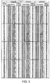
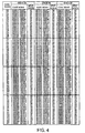
- Figs. 1 to 4 data words of 8 bits 00 to FF are expressed by hexadecimal representations together with corresponding code words of twelve (12) channel bits and next or subsequent states represented by S0 to S2.
- the above-mentioned data words, the code words, and the next states are collectively illustrated in the form of the tables. From this fact, it is readily understood that the code modulation according to the present invention is for modulating the data words of eight (8) bits into the channel bits of twelve (12) bits and carries out eight to twelve (8/12) modulation of the encoding rate (2/3).
- the three code conversion tables illustrated in each of Figs. 1 to 4 are used in the current states S0, S1, and S2, respectively.
- the code words of the 12 channel bits shown in the code conversion tables include symbols "*" and "#” in addition to "0" and "1".
- the symbol “*” is a concatenation bit used on concatenation of two code words and takes “0” and “1” when a leading bit of a subsequent code word takes “1” and "0", respectively.
- the symbol “#” is a DSV control bit and optionally or selectively takes “0” and "1” in accordance with the value of the DSV obtained from the channel bit train produced by a concatenation of the code words.
- the three code conversion tables concerned with the states S0 to S2 shown in Figs. 1 to 4 are successively selected in accordance with the next state shown in the code conversion tables to produce the channel bit train obtained by a concatenation of the code words.
- the channel bit train thus obtained no continuous data "1” appears and the run length indicating the number of continuous occurrence of data "0” is always kept to 10 or less.
- the data "1” does not continuously appear in the channel bit train and the mark or space length produced upon the NRZI conversion on recording the channel bit train has always a length not shorter than 2T (symbol T denotes a channel bit length). That is, it is readily understood that the code conversion tables shown in Figs.
- concatenation rules illustrated in Fig. 5A are used to concatenate or replace code words. According to the concatenation rules, it is possible to exclude, from the channel bit train, a pattern, such as "10101010101" which repeats and continues six or more times of the run length 1.
- the pattern of the run length 1 is recorded as a mark or a space with a shortest length of 2T when the channel bit train is subjected to NRZI conversion.
- the continuous repeat times of the run length 1 are restricted to five times at maximum. It is possible to prevent a low amplitude state from being continued on reproduction.
- the illustrated concatenation rules are used to concatenate two continuous code words and define rules of replacing the code word matched with a predetermined bit train by a code word different in bit series from the former.
- Fig. 5A the concatenation rules are shown and are applied to the code words obtained by the code conversion tables after the concatenation bit "*" is fixed to "0" or "1".
- symbol "X” shown in the previous code words before replacement represents that the bit corresponding to "X” may take either one of "0", “1", “#”, and "*".
- the bit position corresponding to "X” is held at a value before replacement and is therefore kept unchanged.
- the channel bit train replaced on the basis of the concatenation rules include all the patterns that may possibly appear six or more repeat times of run length 1 in the concatenated code words.
- the channel bit train can be replaced by any other patterns that can not be obtained from the word codes in the code conversion tables.
- Concatenation of code words shall be applied at preceding concatenation point first.
- Concatenation rules illustrated in Fig. 5A shall be applied in order of index or rule number at each concatenation point. Some code word may be replaced 2 times to connect with the previous code word and with following or subsequent code word.
- the channel bit train is obtained which has the encoding rate of 2/3, the minimum run length value of 1, the maximum run length value of 10.
- the repeat times of the run length 1 of the channel bit train is restricted to 5 or less.
- the channel bit train is subjected to NRZI conversion and is recorded as data, the conditions are satisfied such that the mark and space length is 2T or more and 11T or less and the continuous repetition of the mark and space of 2T is restricted to 5 times or less.
- the amplitude of the reproduction signal is not sufficiently obtained and therefore the data is erroneously detected.
- the occurrence of the pattern causing the error to occur can be suppressed by limiting the continuous times of the 2T pattern to five or less.
- the mark or space length can be limited to 10T or less even when the 2T pattern continuously appears.
- the entire continuous 2T pattern is shifted by 1T and liable to bring about an error due to the 1T shift.
- the number of the continuous 2T patterns is restricted to 5 or less, such an influence due to the 1T shift can be suppressed to the 12 channel bits or less. Therefore, an adverse influence over 3 bytes can effectively be avoided even in consideration of the boundary of the code words.
- the DSV is obtained by summing 1 or (-1) at every channel bit from the leading bit of the channel bit train, when the positive or the negative polarity appears.
- the DSV serves to indicate the DC component of the code word. As the initial value is assumed to be 0 and the absolute value of the DSV sequentially obtained from the leading bit is close to 0, the DC component is reduced.
- a value of the DSV control bit "#" in the code words is obtained by referring to the code conversion tables and is determined so that the value of the DSV calculated just before the next DSV control bit in relation to the channel bit train becomes close to 0.
- Fig. 6 shows an example of a frequency characteristic of the obtained signal after the NRZI conversion under the DSV control.
- the abscissa denotes the frequency standardized by the channel clock frequency
- the ordinate denotes the power density of the frequency components.
- the amplitude component of random data modulated according to the above method indicates the maximum value at the frequency equal to approximately 1/4 of the channel clock frequency.
- the amplitude component indicates a low amplitude equal to or lower than the maximum value by 20 dB or more, at the frequency equal to or less than that of 1/10,000 of the channel clock.
- the frequency band equal to or less than 1/10,000 of the channel clock corresponds to a servo control band for controlling a position of an optical head.
- the amplitude strength in the frequency band is reduced by 20 dB or more from the maximum value, thereby suppressing the harmful influence given to a servo control signal.
- the precision for the position control is maintained.
- the DSV control bit "0" or "1" in the code conversion tables shown in Figs. 1 to 4 never violates the restriction of the number of the continuous 2T patterns and the run length restriction, irrespective of the code word concatenated before or after the code word.
- the run length of the channel bit train before/after it does not need to be checked and "0" or "1" is arbitrarily selected as the DSV control bit.
- the illustrated circuit is simple in structure.
- the allocation of the DSV control bit is not limited only to the examples in the code conversion tables shown in Figs. 1 to 4.
- the code word including the DSV control bit as one bit is separated into two types of the code word having the DSV control bit "0" and the code word having the DSV control bit "1".
- One of the separated code words may be combined with another code word except for the separated code word and, thereby, the position of the DSV control bit may be changed.
- the code conversion table obtained by the above operation has the same occurrence frequency of the DSV control bit and therefore can expect the same characteristic as the code conversion tables shown in Figs. 1 to 4.
- Fig. 7 shows an example of synchronization patterns or codes (may be often abbreviated to SYNC codes later) suitable to the code modulating method in the present invention.
- the synchronization patterns or SYNC codes are distinguished from the patterns obtained under the concatenation rules illustrated in Fig. 5A and the code conversion tables shown in Figs. 1 to 4. This is because each of the SYNC codes shown in Fig. 7 includes a pattern " 10000000000001" of a run length 12 (may be denoted by 12-run-length).
- the illustrated SYNC codes are composed of four SYNC codes or patterns SY0 to SY3 corresponding to the status information or states S0 to S2. As shown in Fig. 7, the same code or pattern is used for the status information S1 and S2.
- Each SYNC code or pattern is selected on the basis of the status information to be inserted.
- the status information is rendered into S1 or S2 and, thereafter, coding operation is continued. In this way, the feature is maintained such that the pattern continuously repeated 6 or more times of the 1-run-length does not appear with the minimum run length value kept at 1, even if the SYNC code is inserted.
- the illustrated SYNC codes include the patterns of the 12-run-length (the run length 12), the SYNC codes may be formed by patterns not smaller than a run length 11 (namely, 11-run-length). This is because such patterns do not appear in usual code words.
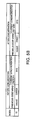
- a concatenation rule or index 10 illustrated in Fig. 5B may be used to concatenate the code word with the SYNC codes so as not to exceed the maximum run length 10.
- the concatenation rules as shown in Fig. 5A are not applied to the concatenation between the SYNC codes and the code word and, therefore, the concatenation rule 10 should be applied.
- the concatenation rule or index 10 includes a predetermined synchronization pattern SY3 which will be described later and which is concatenated as a subsequent or current code word.
- Each SYNC code or pattern includes a single DSV control bit.
- the DSV control bit in the code conversion table is provided for only a part of the code words. Therefore, the DSV control bit might not appear in dependency on the modulating data train.
- the value of the DSV control bit is not determined or fixed until the next DSV control bit appears.
- the value of the DSV control bit is finally determined at every period of the synchronization pattern, by providing the DSV control bit for each of the SYNC codes.
- the four kinds of SYNC codes or patterns SY0 to SY3 are arbitrarily selected and may be regularly selected so as to locate an approximate position of the channel bit train with reference to the detected SYNC code. However, if there is no need for locating the position, the SYNC codes SY0 to SY3 may be selected at random and, alternatively, only the synchronization pattern SY0 may be used. Further, the SYNC codes or patterns are not limited to the illustrated patterns and can have an arbitrary length. Depending on the SYNC codes or patterns, it is possible to modify the SYNC codes together with the status information that is indicative of the code conversion table and that is used just after the synchronization pattern.
- Fig. 8 shows a flowchart showing the above-mentioned code modulating method.
- the status information is initialized to S 1 or S2, and the DSV is initialized to 0.
- the SYNC codes or patterns are sequentially inserted in the order of the synchronization patterns SY0, SY1, SY2, and SY3 at the heads of data frames obtained by separating the data at a constant byte (e.g., 91 bytes).
- the position just after the start of modulation corresponds to a position of inserting the SYNC code or pattern SY0.
- the synchronization pattern SY0 is selected corresponding to the status information (state) S1 or S2.
- the synchronization pattern After inserting the synchronization pattern, the status information is updated to S1 or S2.
- the synchronization pattern includes the DSV control bit after inserting the synchronization pattern. However, before updating the status information, the synchronization pattern does not include the DSV control bit and therefore the bit is not determined.
- the data bits are successively extracted by 8 bits up to the position for inserting the next synchronization pattern and the extracted data bits are converted into the code word by using the code conversion tables. Further, the status information is updated based on the code conversion tables. Furthermore, the code words are concatenated on the basis of the concatenation rules after the replacement of code words. Since the code word just after inserting the synchronization pattern should be concatenated with a previous synchronization pattern, the concatenation rules of the code words may not be applied.
- the code word obtained by using the code conversion tables includes the DSV control bit, a value of the old DSV control bit is determined based on the DSV calculated relative to the channel bit train up to the newly-obtained just-before DSV control bit.
- the synchronization patterns are periodically inserted and the encoding is being advanced.
- the value of the DSV control bit is not always determined until the next DSV control bit appears. However, at the end of the data, the value of the last DSV control bit is determined based on the DSV calculated relative to the channel bit train up to the end data and then the encoding is completed. If the period for inserting the synchronization pattern is determined as approximate 100 bytes, the frequency characteristic shown in Fig. 6 is obtained without influence of the efficiency reduction due to the pattern insertion.
- a part of the DSV control bit indicated in the code conversion table or in the synchronization pattern may be used for controlling the polarity of the recording data.
- the synchronization pattern recorded to the recording disk is limited by using the DSV control bit at the predetermined position.
- the modulating circuit shown in Fig. 9 comprises a code conversion table referring circuit 1, a status register 2, a multiplexer 3, and a synchronization pattern inserting circuit 4.
- the code conversion table referring circuit 1 comprises code conversion tables 101 shown in Figs. 1 to 4.
- the code conversion table referring circuit 1 receives a data train B(t) at every one of 8 bits as well as status information S(t) transmitted from the status register 2.
- the code conversion table referring circuit 1 refers to the code conversion tables 101 shown in Figs. 1 to 4 in accordance with the status information S(t), and outputs a code word X(t) having the 12 channel bits. Further, the code conversion table referring circuit 1 outputs the next status information to the multiplexer 3 in accordance with the code conversion table 101.
- the multiplexer 3 receives the next status information from the synchronization pattern inserting circuit 4, selects it, and outputs the next status information S(t+1) indicating the next status to the status register 2.
- the status register 2 outputs the status information S(t) corresponding to the next data train B(t) to the code conversion table referring circuit 1 and the synchronization pattern inserting circuit 4.
- the code conversion table referring circuit 1 has a plurality of code conversion tables 101, switches the code conversion tables 101 based on the status information S(t) held by the status register 2, and outputs the code word X(t) corresponding to the given data word and the status information S(t+1) indicating the code conversion table to next be referred to.
- a connecting circuit namely, a concatenating circuit 5 is connected to the modulating circuit shown in Fig. 9 at the output terminals of the code conversion table referring circuit 1 and the synchronization pattern inserting circuit 4 and is also connected to a DSV control circuit 6.
- a channel bit train is outputted from the DSV control circuit 6.
- the synchronization pattern inserting circuit 4 outputs the synchronization pattern to be inserted into the channel bit train, based on the status information S(t) held by the status register 2 at a predetermined period, and outputs the status information.
- the status information outputted from the code conversion table referring circuit 1 and the status information outputted from the synchronization pattern inserting circuit 4 are transmitted to the status register 2 via the multiplexer 3, as mentioned above.
- the status register 2 works so that the next status information S(t+1) is updated and is held at each time for outputting the code word from the code conversion table referring circuit 1 and at each time for outputting the synchronization pattern from the synchronization pattern inserting circuit 4.
- the concatenating circuit 5 operates so as to connect or concatenate both of the code word outputted from the code conversion table referring circuit 1 and the synchronization pattern outputted from the synchronization pattern inserting circuit 4 to produce a concatenated code word.
- the concatenating circuit 5 determines a value of a merging or connecting bit "*" included in the last code word to "0" or "1”, and collates the concatenation rule shown in Fig. 5A with the synchronization pattern.
- the concatenation rule matches the synchronization pattern, the code word is replaced and the resultant data is outputted as serial data indicating the channel bit train.
- the DSV control circuit 6 is responsive to the serial data sent from the concatenating circuit 5 and extracts information indicative of the DSV control bit included in the serial data outputted from the concatenating circuit 5. Further, the DSV control circuit 6 determines the DSV control bit and outputs it as the channel bit train so that the value of the DSV is approximate to 0. With the modulating circuit having the above-mentioned structure, the channel bit train suitable for the high-density recording is obtained without the appearance of the pattern which repeats 6 times or more of 1-run-length. Such a channel bit train so that the low-frequency component is sufficiently small.
- the synchronization pattern is extracted from the channel bit train as a result of determining the reproduction signal.
- the boundary of the code words is specified at every set of 12 channel bits on the basis of the extracted synchronization pattern.
- detection is made about each pattern that is replaced on the basis of the obtained boundary from the channel bit train by the use of the concatenation rules and that is returned back to a previous code word or pattern prior to the replacement. Thereafter, the pattern is separated into code words.
- Using the concatenation rules shown in Fig. 5A facilitates detection of the pattern to be reverse-converted and judgment or decision for division of the pattern.
- the decision is realized by replacing the code words under three separation rules shown in Fig. 11.
- the data word of 8 bits is obtained as demodulated results by referring to the demodulation table by the use of the code words obtained in the above-mentioned manner.
- reference symbol "x" included in the previous patterns prior to the replacement denotes the bit may take either "1" or "0".
- the bit corresponding to the reference symbol "x" after the replacement holds the value before the replacement.
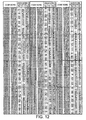
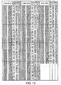
- Figs. 12 and 13 show the demodulation tables for obtaining the data word of the eight (8) bits from the code word of the twelve (12) channel bit.
- three demodulation tables T0 to T2 are shown.
- One of the demodulation tables T0 to T2 to be used is selected in consideration of the demodulation target code word, a next code word just after the target code word, and the synchronization pattern.
- the demodulation table T0 is used.
- the demodulation table T1 When the next code word is started by "0000” or when the next synchronization pattern indicates SY3 of the state 0, the demodulation table T1 is used. When the next code word is started by "01”, “001 ", or "0001” or when the synchronization pattern indicates SY0 to SY3 of the states 1 and 2, the demodulation table T2 is used. The value expressed by the hexadecimal notation is obtained as the data word of the 8 bits, in correspondence to the demodulating target code word.
- the demodulation table T0 is selected and referred to on occurrence of the synchronization pattern corresponding to the status information S0 while the demodulation table T2 is selected and referred to on occurrence of the synchronization pattern corresponding to the status information S1 or S2.
- the data word is produced in the above-mentioned manner.
- the code word of the channel bit train of 12 bits is made to correspond to the data word of 8 bits. Therefore, it is advantageous that any error is not spread or propagated in the above-mentioned method, as compared with a variable block code produced by the use of conversion tables variable in length. This is very effective to suppress the propagation of any error due to restriction of the repeat times of 2T pattern and to reduce an error rate of the data.
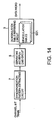
- the channel bit train is inputted to a synchronization pattern detecting circuit 7.
- the synchronization pattern detecting circuit 7 outputs the channel bit train with information indicating the boundary position of the code words with reference to the position of the detected synchronization pattern.
- a separating and replacing circuit 8 detects and replaces the pattern matching a separation rule shown in Fig. 11, and further separates the channel bit train into the code word and outputs it.
- a demodulation table referring circuit 9 converts the above-obtained code word train into the data word having the 8 bits and outputs it.
- the demodulation table referring circuit 9 In order to demodulate the code word having the 12 channel bits, the demodulation table referring circuit 9 refers to the code word subsequent thereto and synchronization pattern, selects a demodulation table 901, and extracts the data word corresponding to the code word.
- the demodulation table referring circuit 9 outputs information indicative of impossibility of the demodulation in relation to the code word which does not appear in the demodulation table.
- the processing is performed as the unit of the code word of the twelve (12) channel bits and, sufficiently, at least the code word just before/after the demodulation is referred to. Therefore, the circuit structure for preventing the propagation of the demodulating error is realized.
- a signal is obtained by the NRZI conversion of the channel bit train, and the signal is recorded in correspondence to an interval of pits and a pit length.
- Such recording is characterized in that the channel clock is stably extracted even when recording is carried out with a high recording density and the detection error can be reduced.
- the reproduction signal obtained from the pits rarely includes components in a servo band and therefore the tracing property of optical pick-up operation for detecting the signal is not deteriorated.
- the channel bit train is subjected to NRZI conversion and recorded in the optical recording medium in the form of the pit length and the pit interval. Further, in the optical recording medium, the channel bit train is formed, except the synchronization pattern, by patterns which have a minimum run length value as 1 and a maximum run length value as 10 and which prohibit the run length 1 from being repeated six times or more. It is needless to say that the synchronization pattern is inserted at a predetermined period. Further, in the optical recording medium, information is recorded so that frequency components of the signal read from the pits are lower than the maximum value of the frequency components by 20 dB or more as the power density at the frequency of 1/10,000 or less of the channel clock frequency.
- the invention is not limited to the above embodiments and, obviously, the embodiments can appropriately be changed within the spirit of the present invention.
- the invention can be applied not only to the reading and writing in the optical recording medium but also to any other recording media.
Landscapes
- Engineering & Computer Science (AREA)
- Signal Processing (AREA)
- Signal Processing For Digital Recording And Reproducing (AREA)
- Dc Digital Transmission (AREA)
Applications Claiming Priority (4)
| Application Number | Priority Date | Filing Date | Title |
|---|---|---|---|
| JP2002366191 | 2002-12-18 | ||
| JP2002366191 | 2002-12-18 | ||
| JP2003399434 | 2003-11-28 | ||
| JP2003399434A JP3957679B2 (ja) | 2002-12-18 | 2003-11-28 | 符号化変調方法および変調装置、復調方法および復調装置、情報記録媒体 |
Publications (2)
| Publication Number | Publication Date |
|---|---|
| EP1431972A2 true EP1431972A2 (fr) | 2004-06-23 |
| EP1431972A3 EP1431972A3 (fr) | 2005-12-14 |
Family
ID=32396329
Family Applications (1)
| Application Number | Title | Priority Date | Filing Date |
|---|---|---|---|
| EP03090444A Withdrawn EP1431972A3 (fr) | 2002-12-18 | 2003-12-18 | Méthode et appareil de modulation de code, méthode et appareil de démodulation et support d'enregistrement d'information |
Country Status (4)
| Country | Link |
|---|---|
| US (1) | US6861965B2 (fr) |
| EP (1) | EP1431972A3 (fr) |
| JP (1) | JP3957679B2 (fr) |
| CN (1) | CN100392984C (fr) |
Families Citing this family (23)
| Publication number | Priority date | Publication date | Assignee | Title |
|---|---|---|---|---|
| JP4178795B2 (ja) * | 2002-01-23 | 2008-11-12 | ソニー株式会社 | 変調装置および方法、dsv制御ビット生成方法、記録媒体、並びにプログラム |
| JP4141175B2 (ja) * | 2002-05-14 | 2008-08-27 | ソニー株式会社 | データ記録媒体、データ記録方法および装置 |
| GB0301700D0 (en) * | 2003-01-24 | 2003-02-26 | Macrovision Corp | The copy protection of optical discs |
| JP3960263B2 (ja) * | 2003-05-21 | 2007-08-15 | ソニー株式会社 | データ記録方法 |
| JP3965385B2 (ja) * | 2003-12-24 | 2007-08-29 | 株式会社日立製作所 | Dvd記録方法及びdvd記録装置 |
| JP3969399B2 (ja) * | 2004-03-18 | 2007-09-05 | 株式会社日立製作所 | 記録方法及び記録装置 |
| CN1942966B (zh) * | 2004-04-15 | 2010-05-12 | 皇家飞利浦电子股份有限公司 | 用于光学存储系统的dc控制编码 |
| KR100565079B1 (ko) * | 2004-09-08 | 2006-03-30 | 삼성전자주식회사 | 코드 생성 방법, 변조 장치 및 변조 방법 |
| US7701825B2 (en) * | 2005-06-17 | 2010-04-20 | Macrovision Corporation | Apparatus for and a method of authenticating recording media |
| KR100652434B1 (ko) * | 2005-10-06 | 2006-12-01 | 삼성전자주식회사 | 광디스크 기록/재생 장치의 데이터 변조 방법 및 데이터변조 장치 |
| JP4692234B2 (ja) * | 2005-11-10 | 2011-06-01 | ソニー株式会社 | 変調テーブル、変調装置および方法、プログラム、並びに記録媒体 |
| CN100386812C (zh) * | 2005-12-16 | 2008-05-07 | 清华大学 | 编码调制方法及装置、解调方法及装置 |
| KR20080096745A (ko) | 2006-01-23 | 2008-11-03 | 로무 가부시키가이샤 | 부호화 장치, 복호 장치, 진폭 조정 장치, 기록 정보 판독장치, 신호 처리 장치 및 기억 시스템 |
| JP4735975B2 (ja) * | 2006-04-28 | 2011-07-27 | ソニー株式会社 | 変調装置および方法、プログラム、並びに記録媒体 |
| JP2007334992A (ja) | 2006-06-15 | 2007-12-27 | Hitachi Ltd | 光ディスク再生装置および光ディスク再生方法 |
| US7557739B1 (en) * | 2006-10-17 | 2009-07-07 | Marvell International Ltd. | Four-to-six modulation encoder |
| DE102006056903B4 (de) * | 2006-12-02 | 2008-07-17 | Semikron Elektronik Gmbh & Co. Kg | Verfahren zur digitalen Kommunikation zwischen zwei Funktionsblöcken eines leistungselektronischen Bauteils |
| JP4893284B2 (ja) * | 2006-12-11 | 2012-03-07 | 株式会社日立製作所 | 光ディスク装置および変調方法 |
| KR20090085257A (ko) * | 2008-02-04 | 2009-08-07 | 삼성전자주식회사 | Dsv 제어 방법, 이에 적합한 기록매체 및 장치 |
| CN101908892B (zh) * | 2009-06-04 | 2013-02-27 | 清华大学 | 一种码率为1的游长受限调制编码方法 |
| JP5399975B2 (ja) | 2010-05-14 | 2014-01-29 | 太陽誘電株式会社 | 可視光通信用受信機、可視光通信システム、及び可視光通信方法 |
| JP7320927B2 (ja) * | 2018-07-02 | 2023-08-04 | ルネサスエレクトロニクス株式会社 | 半導体装置及び通信システム |
| CN112887088B (zh) * | 2021-01-21 | 2022-04-22 | 西北大学 | 一种高斯调制方法及连续变量量子安全直接通信系统 |
Citations (4)
| Publication number | Priority date | Publication date | Assignee | Title |
|---|---|---|---|---|
| JPH10340543A (ja) | 1997-04-08 | 1998-12-22 | Sony Corp | エンコード装置、デコード装置、エンコード方法、及びデコード方法 |
| JP2000332613A (ja) | 1999-05-25 | 2000-11-30 | Victor Co Of Japan Ltd | 変調装置、復調装置 |
| EP1225701A2 (fr) | 2001-01-12 | 2002-07-24 | Victor Company of Japan, Ltd. | Système de modulation |
| EP1265241A1 (fr) | 2001-06-07 | 2002-12-11 | Victor Company Of Japan, Limited | Méthode de codage à longueur de course limitée |
Family Cites Families (5)
| Publication number | Priority date | Publication date | Assignee | Title |
|---|---|---|---|---|
| JP3243140B2 (ja) * | 1995-02-20 | 2002-01-07 | パイオニア株式会社 | データ変換方式 |
| TW362305B (en) * | 1996-10-18 | 1999-06-21 | Koninkl Philips Electronics Nv | Apparatus and method for converting a sequence of m-bit information words into a modulated signal |
| US6091347A (en) * | 1997-05-23 | 2000-07-18 | Sony Corporation | Device and method for modulation and transmission medium |
| JP3985173B2 (ja) * | 1998-05-29 | 2007-10-03 | ソニー株式会社 | 変調装置および方法、復調装置および方法、並びにデータ格納媒体 |
| US6445313B2 (en) * | 2000-02-07 | 2002-09-03 | Lg Electronics Inc. | Data modulating/demodulating method and apparatus for optical recording medium |
-
2003
- 2003-11-28 JP JP2003399434A patent/JP3957679B2/ja not_active Expired - Fee Related
- 2003-12-17 US US10/736,785 patent/US6861965B2/en not_active Expired - Fee Related
- 2003-12-18 CN CNB2003101232328A patent/CN100392984C/zh not_active Expired - Fee Related
- 2003-12-18 EP EP03090444A patent/EP1431972A3/fr not_active Withdrawn
Patent Citations (4)
| Publication number | Priority date | Publication date | Assignee | Title |
|---|---|---|---|---|
| JPH10340543A (ja) | 1997-04-08 | 1998-12-22 | Sony Corp | エンコード装置、デコード装置、エンコード方法、及びデコード方法 |
| JP2000332613A (ja) | 1999-05-25 | 2000-11-30 | Victor Co Of Japan Ltd | 変調装置、復調装置 |
| EP1225701A2 (fr) | 2001-01-12 | 2002-07-24 | Victor Company of Japan, Ltd. | Système de modulation |
| EP1265241A1 (fr) | 2001-06-07 | 2002-12-11 | Victor Company Of Japan, Limited | Méthode de codage à longueur de course limitée |
Also Published As
| Publication number | Publication date |
|---|---|
| EP1431972A3 (fr) | 2005-12-14 |
| JP3957679B2 (ja) | 2007-08-15 |
| JP2004213863A (ja) | 2004-07-29 |
| US6861965B2 (en) | 2005-03-01 |
| CN100392984C (zh) | 2008-06-04 |
| CN1531208A (zh) | 2004-09-22 |
| US20040207545A1 (en) | 2004-10-21 |
Similar Documents
| Publication | Publication Date | Title |
|---|---|---|
| US6861965B2 (en) | Code modulating method and code modulating apparatus, demodulating method and demodulating apparatus, and information recording medium | |
| EP1083687B1 (fr) | Procede et dispositif de modulation et demodulation de donnees a l'aide d'un code a longueur variable | |
| JP3985173B2 (ja) | 変調装置および方法、復調装置および方法、並びにデータ格納媒体 | |
| JP3722331B2 (ja) | 変調装置および方法、並びに記録媒体 | |
| KR100954986B1 (ko) | 변조 장치 및 방법 | |
| US6898166B2 (en) | Synchronous signal generating method, recording apparatus, transmitting apparatus, recording medium, and transmission medium | |
| JPH11177433A (ja) | 復調装置および方法、並びに提供媒体 | |
| KR100615418B1 (ko) | 디지털 데이터 복조장치, 디지털 데이터 변조장치, 및디지털 데이터 변복조장치 | |
| JP3757918B2 (ja) | 符号化変調方法および変調装置、復調方法および復調装置 | |
| JP4059884B2 (ja) | デジタルデータ復調装置およびデジタルデータ変復調装置 | |
| JP2007207423A (ja) | 符号化変調方法および変調装置、復調方法および復調装置 | |
| JP4366662B2 (ja) | 変調装置、変調方法、記録媒体 | |
| JP2006311598A (ja) | 変調装置および方法、記録媒体、並びに復調装置および方法 | |
| TW200425070A (en) | Code modulating method and code modulating apparatus, demodulating method and demodulating apparatus, and information recording medium |
Legal Events
| Date | Code | Title | Description |
|---|---|---|---|
| PUAI | Public reference made under article 153(3) epc to a published international application that has entered the european phase |
Free format text: ORIGINAL CODE: 0009012 |
|
| AK | Designated contracting states |
Kind code of ref document: A2 Designated state(s): AT BE BG CH CY CZ DE DK EE ES FI FR GB GR HU IE IT LI LU MC NL PT RO SE SI SK TR |
|
| AX | Request for extension of the european patent |
Extension state: AL LT LV MK |
|
| PUAL | Search report despatched |
Free format text: ORIGINAL CODE: 0009013 |
|
| AK | Designated contracting states |
Kind code of ref document: A3 Designated state(s): AT BE BG CH CY CZ DE DK EE ES FI FR GB GR HU IE IT LI LU MC NL PT RO SE SI SK TR |
|
| AX | Request for extension of the european patent |
Extension state: AL LT LV MK |
|
| RIC1 | Information provided on ipc code assigned before grant |
Ipc: 7G 11B 20/00 B Ipc: 7G 11B 20/14 A |
|
| 17P | Request for examination filed |
Effective date: 20051217 |
|
| AKX | Designation fees paid |
Designated state(s): DE FR GB |
|
| 17Q | First examination report despatched |
Effective date: 20071116 |
|
| STAA | Information on the status of an ep patent application or granted ep patent |
Free format text: STATUS: THE APPLICATION IS DEEMED TO BE WITHDRAWN |
|
| 18D | Application deemed to be withdrawn |
Effective date: 20120725 |