EP1432231A2 - Dispositif et procédé d'enregistrement exempte de bruite des images en deux dimensions de haute resolution - Google Patents
Dispositif et procédé d'enregistrement exempte de bruite des images en deux dimensions de haute resolution Download PDFInfo
- Publication number
- EP1432231A2 EP1432231A2 EP03028429A EP03028429A EP1432231A2 EP 1432231 A2 EP1432231 A2 EP 1432231A2 EP 03028429 A EP03028429 A EP 03028429A EP 03028429 A EP03028429 A EP 03028429A EP 1432231 A2 EP1432231 A2 EP 1432231A2
- Authority
- EP
- European Patent Office
- Prior art keywords
- scan
- scanning
- pattern
- positions
- minimum
- Prior art date
- Legal status (The legal status is an assumption and is not a legal conclusion. Google has not performed a legal analysis and makes no representation as to the accuracy of the status listed.)
- Withdrawn
Links
- 238000000034 method Methods 0.000 title claims abstract description 28
- 238000005070 sampling Methods 0.000 claims abstract description 8
- 230000002123 temporal effect Effects 0.000 claims description 9
- 230000007246 mechanism Effects 0.000 claims description 6
- 230000009467 reduction Effects 0.000 abstract description 4
- 230000015572 biosynthetic process Effects 0.000 description 6
- 241001136792 Alle Species 0.000 description 4
- 238000010586 diagram Methods 0.000 description 3
- 238000006073 displacement reaction Methods 0.000 description 3
- 230000003287 optical effect Effects 0.000 description 2
- 238000001454 recorded image Methods 0.000 description 2
- 238000009827 uniform distribution Methods 0.000 description 2
- 208000003443 Unconsciousness Diseases 0.000 description 1
- 238000013459 approach Methods 0.000 description 1
- 238000001514 detection method Methods 0.000 description 1
- 238000009826 distribution Methods 0.000 description 1
- 230000000694 effects Effects 0.000 description 1
- 238000011156 evaluation Methods 0.000 description 1
- 238000003384 imaging method Methods 0.000 description 1
- 230000006872 improvement Effects 0.000 description 1
- 238000003780 insertion Methods 0.000 description 1
- 230000037431 insertion Effects 0.000 description 1
- 238000012545 processing Methods 0.000 description 1
- 230000008521 reorganization Effects 0.000 description 1
- 230000035945 sensitivity Effects 0.000 description 1
- 210000002023 somite Anatomy 0.000 description 1
- 230000001629 suppression Effects 0.000 description 1
- 230000007704 transition Effects 0.000 description 1
Images


Classifications
-
- H—ELECTRICITY
- H04—ELECTRIC COMMUNICATION TECHNIQUE
- H04N—PICTORIAL COMMUNICATION, e.g. TELEVISION
- H04N25/00—Circuitry of solid-state image sensors [SSIS]; Control thereof
- H04N25/48—Increasing resolution by shifting the sensor relative to the scene
Definitions
- the invention relates to a device for receiving high-resolution Two-dimensional images with moving image sensor and a method for Create optimized scan patterns for two-dimensional scanning Image recording systems, in particular for receiving finger, hand or Footprints or other geometrically highly accurate images to be evaluated which a movement can not be excluded.
- high-resolution image capture of objects e.g. Finger and Handprinting
- various recording methods can be used. So is for example, it is possible to use high-resolution image sensors to capture a single image of the image entire object to record.
- the rule still applies today that sufficiently high-resolution image sensors with appropriate parameters only at very high cost.
- a high-resolution Image also from several temporally successively and spatially offset recorded Images are composed at a lower resolution. It is the Image sensor moved between individual images to multiple images one after the other, which are then put together to form the result picture.
- the foregoing methods are scanning (i.e., by sensor motion scanning) recording method, since the camera image sensor for recording a entire picture is moved several times.
- the recording of high-resolution images with scanning recording method comes especially in the detection of stationary or little moving picture objects are used.
- the Microscan method was developed in order to achieve a high optical image resolution of the resulting image with available low-resolution camera sensors (with low pixel density).
- the main focus in performing the mechanical scanning of the Microscan method is to minimize the scan paths of the camera and thus minimize scan and image capture time.
- the camera is moved meandering during image acquisition starting at position 1 (see FIG. 2c for illustrating a 3 ⁇ 4 image scan).
- the Microscan method is used primarily in small objects with high resolution requirements and takes into account the fact that conventionally available image sensors (in particular CCD sensors) between the photosensitive image sensor elements have light-insensitive areas which serve to derive the signals of the sensor elements.
- the invention has for its object to provide a new way to accommodate high-resolution two-dimensional images with resolution-increasing Two-dimensional sensor movement to find the simple means a Significant reduction of image interference, which occurs during the movement of the object during the scan movement of the image sensor, reached.
- the object with a device for receiving high-resolution two-dimensional images in which for a resolution-increasing Multiplication of the scanned pixels, a scanning mechanism for two-dimensional Movement of the image sensor is present, solved by that at a selected scan grid with n scan positions in x-direction and m scan positions in y direction is a scan pattern for the sensor movement is present, in the form of Sample numbers has a fixed sequence of approached scan positions, wherein for locally adjacent scan positions in the x-direction and in the y-direction respectively a time interval, represented as the difference of the sample numbers, of at least two Scanning steps is available.
- the scan pattern for a given scan grid is optimized such that the time intervals between respectively locally adjacent scan positions in the x and y directions have a maximum and a minimum in the entire scan pattern that are as close as possible to each other.
- the scanning pattern characterized above is preferably used for image recorders with an nxm microscan. It can also be useful for a given nxm macroscan.
- the thus configured scan pattern is advantageously integrated into the drive software for the scanning mechanism of the image sensor.
- the selection of the appropriate scan pattern is preferably made by comparing the differences of maximum and minimum of each scan pattern, with the scan pattern having the smallest difference of maximum and minimum of the sample count differences being an optimum.
- Another convenient and more stringent criterion for selecting the appropriate scan pattern is by comparing the quotient of the minimum and maximum of each scan pattern by selecting the scan pattern having the largest minimum to maximum ratio of sample number differences as optimal.
- the inventive device consists of an image sensor by means of a scanning mechanism (not shown) in a predetermined scan grid 12 - as shown schematically in Fig. 1 as 3x4 scan grid - with a scan pattern 3, in which not the shortest displacement of the image sensor element 11, the target ,
- the scanning positions 14 are represented in the illustration of Fig. 1 by juxtaposed positions of a selected sensor element 11, wherein by sampling numbers 31, the consecutive numbering of the scan steps 13 over time is shown. It should be noted at this point that the juxtaposition of the scan positions 14 only serves the purpose of simplification and, in reality, a local overlap of the scan positions 14 is frequently provided.
- the suppression of artifacts 51 (only shown in FIG. 11) in result image 2 (see FIG. 2 b), which is shown in FIG.
- Fig. 2a is intended first to illustrate the conventional scanning principle of imagers with a macroscan.
- the aim of the macroscan is that the image section scanned by the image sensor 1 is shifted stepwise over a much larger image area of an object.
- By juxtaposing the scanned image excerpts of the size of the entire image sensor 1 with the edge length a produces the result image 2, which is composed in this case of a 2x2 macroscan.
- between the positions of the image sensor 1, which may also be different for the two dimensions of the image sensor 1, is in each case an edge length a of the image sensor 1 in a different direction.
- FIG. 2b shows the state of the art for image scanning by means of a 2x2 microscan.
- the image sensor 1 consists for example of 4x4 sensor elements 11 and is shifted by half the pixel pitch p / 2.
- the result image 2 which results from the so-called interleaving of the signals read out, exhibits a quadruple increase in pixel density and hence improved triggering as a result of the selected displacement path, which is shown as scan pattern 3 for the fourth sensor element 11 of the first line.
- FIG. 2 c again shows the same situation of FIG.
- the individual scanning steps 13 run in an ordered manner in the scanning grid 12, wherein the trajectory of the scanning steps 13 for clarifying the scanning pattern 3 has again been emphasized in addition to the scheme of the scan positions 14 approached one after the other whose temporal sequence is characterized by the scanning numbers 31.
- the designation (maximum, minimum) is used to classify the scanning patterns 3, the maximum 42 being the maximum temporal difference 32 and the minimum 41 being the minimum temporal difference 32 of all the scanning numbers 31 of spatially adjacent scanning positions 33 of a selected sensor element 11 and the minimum Differences 32 is used to classify the scanning patterns 3 into classes.
- the evaluation (11, 1) thus results - as can be easily read from FIG.
- Fig. 7 shows the list of scan pattern classes according to the above prescriptions of the 1st to 3rd steps of the algorithm for the 3x4 scan grid 12.
- the scan positions 33 of a selected sensor element 11 have been numbered from 1 to 12.
- a scanning pattern class 4 is to be identified by the minimum difference 32 of the scanning numbers 31 of adjacent scanning positions 33.
- the class 4 of scan patterns 3, which has the value one as the minimum 41 of the differences 32, is rejected immediately in the fourth step of the method, so that direct neighborhoods of the scan positions 33 (also in the transition to scan positions 34, cf. FIG. 9) are excluded ,
- This class 4 labeled (k, 1) includes six scan patterns 3.
- the scanning patterns (6, 2) and (8, 4) have the greatest proximity of the minimum and maximum of the sample number differences. If one now decides with a difference criterion between maximum and minimum, both scan patterns (6,2) and (8,4) are the same and can be selected as desired for the programming of the scanning mechanism of the image sensor 1.
- Fig. 8 shows the scanning pattern classes 4 for a 3x3 scan raster for the sake of explanation.
- the scan positions 33 according to FIG. 10 are in this case 1 to 9 numbered.
- As class division results from the permutations of Order of scan positions 33 only two classes 4 with four and two, respectively represented scan patterns 3, of which the first class (k, 1) by the above specified 4th procedural rule deleted.
- the remaining two scanning patterns 3 of the second class 4 with the marking (k, 2) have the classifications (8,2) and (7,2) and when using each of the selection steps 5.1 or 5.2, the Classification (7.2) as optimized scan pattern 43.
- FIG. 9 shows the scanning pattern 43 optimized according to the invention for a 3 ⁇ 4 scan grid 12 by identifying the scan positions 33 and 34 with sample numbers 31 and indicating differences 32 (as time intervals) of the locally adjacent scan positions 33 and 34.
- FIG. 9 is schematically applied in the same manner as FIG. 3 and embodies a representation equivalent to the scanning pattern 3 of FIG. 1 according to the invention.
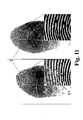
- the significantly improved scanning quality of the scanning pattern 3 of FIG. 9 compared with FIG. 3 (prior art ffleander scan) can be seen in FIG. 11.
- FIG. 11 are the images of two images with a microscan in the 3x4 scan grid, in which the imaged finger has moved minimally, with the different scanning patterns 3 (according to FIGS. 3 and 9) have been detected.
- the left-hand image was taken with a meander-shaped scan [in the class diagram of FIG. 7: using the scan designation 3 with the class designation (11,1)] and shows clearly visible linear artifacts 51.
- the right-hand image was generated using the scan pattern 43 with classification (8,4) from Fig. 7 created. It can be seen that with the method according to the invention, the pronounced false line structures or linear artifacts 51 of the imaged fingerprint 5 do not occur any more (as in the left-hand illustration of FIG. 11) and the method thus has a significantly better behavior with respect to movements of the object shows.
- a significant improvement of image pickup devices that use a microscan to increase the resolution can be achieved with respect to susceptibility to image errors due to low object movement.
- the inventive method is with relatively little effort by Revision of the driver software of a scanning image sensor 1 and one-time Recalibration of image acquisition with this new software for all previously known optically scanning image sensor applicable.
- the application of the inventive method for generating a suitable scan pattern 3 are other than the above-mentioned scan grid 12 no limits, so that optimized for any two-dimensional scan mode Scan pattern 43 can be found as one stored in software Scan configuration determines the nature and quality of the image sensor.
Landscapes
- Engineering & Computer Science (AREA)
- Multimedia (AREA)
- Signal Processing (AREA)
- Facsimile Scanning Arrangements (AREA)
- Image Input (AREA)
Applications Claiming Priority (2)
| Application Number | Priority Date | Filing Date | Title |
|---|---|---|---|
| DE10261665 | 2002-12-20 | ||
| DE10261665A DE10261665B3 (de) | 2002-12-20 | 2002-12-20 | Einrichtung und Verfahren zur störungsarmen Aufnahme von hochaufgelösten zweidimensionalen Bildern |
Publications (2)
| Publication Number | Publication Date |
|---|---|
| EP1432231A2 true EP1432231A2 (fr) | 2004-06-23 |
| EP1432231A3 EP1432231A3 (fr) | 2005-02-02 |
Family
ID=31896379
Family Applications (1)
| Application Number | Title | Priority Date | Filing Date |
|---|---|---|---|
| EP03028429A Withdrawn EP1432231A3 (fr) | 2002-12-20 | 2003-12-11 | Dispositif et procédé d'enregistrement exempte de bruite des images en deux dimensions de haute resolution |
Country Status (4)
| Country | Link |
|---|---|
| US (1) | US20040136612A1 (fr) |
| EP (1) | EP1432231A3 (fr) |
| JP (1) | JP2004206706A (fr) |
| DE (1) | DE10261665B3 (fr) |
Cited By (1)
| Publication number | Priority date | Publication date | Assignee | Title |
|---|---|---|---|---|
| DE102012107191A1 (de) | 2012-08-06 | 2014-02-06 | Jenoptik Optical Systems Gmbh | Verfahren zur hochauflösenden digitalen Farbbildaufnahme mit hohem Dynamikbereich |
Families Citing this family (47)
| Publication number | Priority date | Publication date | Assignee | Title |
|---|---|---|---|---|
| US8229184B2 (en) | 2004-04-16 | 2012-07-24 | Validity Sensors, Inc. | Method and algorithm for accurate finger motion tracking |
| US8165355B2 (en) | 2006-09-11 | 2012-04-24 | Validity Sensors, Inc. | Method and apparatus for fingerprint motion tracking using an in-line array for use in navigation applications |
| US8175345B2 (en) | 2004-04-16 | 2012-05-08 | Validity Sensors, Inc. | Unitized ergonomic two-dimensional fingerprint motion tracking device and method |
| US8358815B2 (en) | 2004-04-16 | 2013-01-22 | Validity Sensors, Inc. | Method and apparatus for two-dimensional finger motion tracking and control |
| US8447077B2 (en) | 2006-09-11 | 2013-05-21 | Validity Sensors, Inc. | Method and apparatus for fingerprint motion tracking using an in-line array |
| US8077935B2 (en) * | 2004-04-23 | 2011-12-13 | Validity Sensors, Inc. | Methods and apparatus for acquiring a swiped fingerprint image |
| US8131026B2 (en) | 2004-04-16 | 2012-03-06 | Validity Sensors, Inc. | Method and apparatus for fingerprint image reconstruction |
| WO2006041780A1 (fr) | 2004-10-04 | 2006-04-20 | Validity Sensors, Inc. | Groupes de detection d'empreintes digitales comprenant un substrat |
| US8072502B2 (en) * | 2005-12-12 | 2011-12-06 | Sony Ericsson Mobile Communications Ab | Multi-mega pixel resolution with small sensor |
| US8107212B2 (en) | 2007-04-30 | 2012-01-31 | Validity Sensors, Inc. | Apparatus and method for protecting fingerprint sensing circuitry from electrostatic discharge |
| US8290150B2 (en) | 2007-05-11 | 2012-10-16 | Validity Sensors, Inc. | Method and system for electronically securing an electronic device using physically unclonable functions |
| US8204281B2 (en) | 2007-12-14 | 2012-06-19 | Validity Sensors, Inc. | System and method to remove artifacts from fingerprint sensor scans |
| US8276816B2 (en) | 2007-12-14 | 2012-10-02 | Validity Sensors, Inc. | Smart card system with ergonomic fingerprint sensor and method of using |
| US8116540B2 (en) | 2008-04-04 | 2012-02-14 | Validity Sensors, Inc. | Apparatus and method for reducing noise in fingerprint sensing circuits |
| US7953258B2 (en) * | 2008-04-04 | 2011-05-31 | Validity Sensors, Inc. | Fingerprint sensing circuit having programmable sensing patterns |
| US8005276B2 (en) | 2008-04-04 | 2011-08-23 | Validity Sensors, Inc. | Apparatus and method for reducing parasitic capacitive coupling and noise in fingerprint sensing circuits |
| GB2474999B (en) | 2008-07-22 | 2013-02-20 | Validity Sensors Inc | System and method for securing a device component |
| JP5206218B2 (ja) * | 2008-08-20 | 2013-06-12 | 富士通株式会社 | 指紋画像取得装置、指紋認証装置、指紋画像取得方法及び指紋認証方法 |
| US8391568B2 (en) | 2008-11-10 | 2013-03-05 | Validity Sensors, Inc. | System and method for improved scanning of fingerprint edges |
| US8600122B2 (en) | 2009-01-15 | 2013-12-03 | Validity Sensors, Inc. | Apparatus and method for culling substantially redundant data in fingerprint sensing circuits |
| US8278946B2 (en) | 2009-01-15 | 2012-10-02 | Validity Sensors, Inc. | Apparatus and method for detecting finger activity on a fingerprint sensor |
| US8374407B2 (en) | 2009-01-28 | 2013-02-12 | Validity Sensors, Inc. | Live finger detection |
| US8162431B2 (en) * | 2009-04-07 | 2012-04-24 | Xerox Corporation | System and method for detecting weak and missing ink jets in an ink jet printer |
| US8547426B2 (en) * | 2009-06-15 | 2013-10-01 | Identix Incorporated | Low settle time micro-scanning system |
| US9400911B2 (en) | 2009-10-30 | 2016-07-26 | Synaptics Incorporated | Fingerprint sensor and integratable electronic display |
| US9274553B2 (en) | 2009-10-30 | 2016-03-01 | Synaptics Incorporated | Fingerprint sensor and integratable electronic display |
| US9336428B2 (en) | 2009-10-30 | 2016-05-10 | Synaptics Incorporated | Integrated fingerprint sensor and display |
| US8866347B2 (en) | 2010-01-15 | 2014-10-21 | Idex Asa | Biometric image sensing |
| US8421890B2 (en) | 2010-01-15 | 2013-04-16 | Picofield Technologies, Inc. | Electronic imager using an impedance sensor grid array and method of making |
| US8791792B2 (en) | 2010-01-15 | 2014-07-29 | Idex Asa | Electronic imager using an impedance sensor grid array mounted on or about a switch and method of making |
| US9666635B2 (en) | 2010-02-19 | 2017-05-30 | Synaptics Incorporated | Fingerprint sensing circuit |
| US8716613B2 (en) | 2010-03-02 | 2014-05-06 | Synaptics Incoporated | Apparatus and method for electrostatic discharge protection |
| US9001040B2 (en) | 2010-06-02 | 2015-04-07 | Synaptics Incorporated | Integrated fingerprint sensor and navigation device |
| US8331096B2 (en) | 2010-08-20 | 2012-12-11 | Validity Sensors, Inc. | Fingerprint acquisition expansion card apparatus |
| US8538097B2 (en) | 2011-01-26 | 2013-09-17 | Validity Sensors, Inc. | User input utilizing dual line scanner apparatus and method |
| US8594393B2 (en) | 2011-01-26 | 2013-11-26 | Validity Sensors | System for and method of image reconstruction with dual line scanner using line counts |
| US9406580B2 (en) | 2011-03-16 | 2016-08-02 | Synaptics Incorporated | Packaging for fingerprint sensors and methods of manufacture |
| US10043052B2 (en) | 2011-10-27 | 2018-08-07 | Synaptics Incorporated | Electronic device packages and methods |
| US9195877B2 (en) | 2011-12-23 | 2015-11-24 | Synaptics Incorporated | Methods and devices for capacitive image sensing |
| US9785299B2 (en) | 2012-01-03 | 2017-10-10 | Synaptics Incorporated | Structures and manufacturing methods for glass covered electronic devices |
| US9251329B2 (en) | 2012-03-27 | 2016-02-02 | Synaptics Incorporated | Button depress wakeup and wakeup strategy |
| US9268991B2 (en) | 2012-03-27 | 2016-02-23 | Synaptics Incorporated | Method of and system for enrolling and matching biometric data |
| US9137438B2 (en) | 2012-03-27 | 2015-09-15 | Synaptics Incorporated | Biometric object sensor and method |
| US9600709B2 (en) | 2012-03-28 | 2017-03-21 | Synaptics Incorporated | Methods and systems for enrolling biometric data |
| US9152838B2 (en) | 2012-03-29 | 2015-10-06 | Synaptics Incorporated | Fingerprint sensor packagings and methods |
| EP2836960B1 (fr) | 2012-04-10 | 2018-09-26 | Idex Asa | Détection biométrique |
| US9665762B2 (en) | 2013-01-11 | 2017-05-30 | Synaptics Incorporated | Tiered wakeup strategy |
Family Cites Families (11)
| Publication number | Priority date | Publication date | Assignee | Title |
|---|---|---|---|---|
| EP0131387B1 (fr) * | 1983-06-15 | 1989-03-08 | Kabushiki Kaisha Toshiba | Capteur d'images à l'état solide à haute résolution |
| US5235167A (en) * | 1988-10-21 | 1993-08-10 | Symbol Technologies, Inc. | Laser scanning system and scanning method for reading bar codes |
| JP2753541B2 (ja) * | 1990-02-19 | 1998-05-20 | 株式会社ニコン | 静止画撮像装置 |
| US5021891A (en) * | 1990-02-27 | 1991-06-04 | Qualcomm, Inc. | Adaptive block size image compression method and system |
| KR950010913B1 (ko) * | 1992-07-23 | 1995-09-25 | 삼성전자주식회사 | 가변장부호화 및 복호화시스템 |
| US6195125B1 (en) * | 1995-08-11 | 2001-02-27 | Canon Kabushiki Kaisha | Pixel shifting image sensor with a different number of images sensed in each mode |
| JPH09307802A (ja) * | 1996-05-10 | 1997-11-28 | Canon Inc | 固体撮像装置 |
| JP4536170B2 (ja) * | 1996-12-27 | 2010-09-01 | シャープ株式会社 | 撮像装置 |
| KR100318747B1 (ko) * | 1998-12-31 | 2002-02-19 | 윤종용 | 디지털 스틸 카메라의 고화질 이미지 생성방법및 그 장치 |
| EP1213568B1 (fr) * | 2000-12-08 | 2005-12-28 | Gretag-Macbeth AG | Dispositif pour la mesure pixel par pixel d'un objet de mesure plat |
| DE10163351C1 (de) * | 2001-12-14 | 2003-06-26 | Heimann Biometric Systems Gmbh | Verfahren und Anordnung zur verzerrungsarmen Aufnahme von an einer Kontaktfläche durch gestörte Totalreflexion entstehenden Intensitätsmustern |
-
2002
- 2002-12-20 DE DE10261665A patent/DE10261665B3/de not_active Expired - Fee Related
-
2003
- 2003-12-11 EP EP03028429A patent/EP1432231A3/fr not_active Withdrawn
- 2003-12-12 JP JP2003414718A patent/JP2004206706A/ja active Pending
- 2003-12-19 US US10/741,878 patent/US20040136612A1/en not_active Abandoned
Cited By (1)
| Publication number | Priority date | Publication date | Assignee | Title |
|---|---|---|---|---|
| DE102012107191A1 (de) | 2012-08-06 | 2014-02-06 | Jenoptik Optical Systems Gmbh | Verfahren zur hochauflösenden digitalen Farbbildaufnahme mit hohem Dynamikbereich |
Also Published As
| Publication number | Publication date |
|---|---|
| EP1432231A3 (fr) | 2005-02-02 |
| JP2004206706A (ja) | 2004-07-22 |
| DE10261665B3 (de) | 2004-03-25 |
| US20040136612A1 (en) | 2004-07-15 |
Similar Documents
| Publication | Publication Date | Title |
|---|---|---|
| DE10261665B3 (de) | Einrichtung und Verfahren zur störungsarmen Aufnahme von hochaufgelösten zweidimensionalen Bildern | |
| DE19544178B4 (de) | Vorrichtung zum scannenden Digitalisieren von Bildvorlagen sowie Verfahren zu deren Betrieb | |
| DE69733978T2 (de) | Bilddateninterpolationsgerät | |
| DE3622058C2 (fr) | ||
| DE69925430T2 (de) | Verfahren zur Reduzierung von Artefakterscheinungen in der Raster-Elektronenmikroskopie | |
| DE102008034304A1 (de) | Eingebautes Bildverarbeitungsgerät für Fahrzeuge | |
| EP3085070B1 (fr) | Dispositif de prise de vue avec une optique à plusieurs canaux | |
| DE3923449A1 (de) | Verfahren zum bestimmen von kanten in bildern | |
| DE102006011707A1 (de) | Verfahren und Vorrichtung zum Erzeugen einer strukturfreien fiberskopischen Aufnahme | |
| DE19733338A1 (de) | Röntgendiagnostikeinrichtung zur Erstellung von Panorama-Schichtaufnahmen von Körperteilen eines Patienten | |
| DE3390498T1 (de) | Rastergravierungssystem für elektromechanische Gravierer | |
| EP4183129B1 (fr) | Procédé et dispositif pour réduire les erreurs de crénelage dans les images des dispositifs d'affichage à base de pixels et pour l'évaluation des dispositifs d'affichage de ce type | |
| DE2858688C2 (fr) | ||
| CH686207A5 (de) | Verfahren und Einrichtung zum Erzeugen eines Bilds hoher Auflosung. | |
| DE69430976T2 (de) | Rastereletronenmikroskop und Bilderzeugungsverfahren mittels solchen Mikroskop | |
| DE102016203392B3 (de) | Bildinspektionsverfahren mit mehreren Kameras | |
| DE3524505A1 (de) | Bilderkennungsvorrichtung | |
| DE102018124401A1 (de) | Verfahren zum Aufnehmen eines Bildes mit einem Teilchenmikroskop | |
| DE112020006936T5 (de) | Kamerabelichtungsverarbeitungsverfahren und -system | |
| EP1202561B1 (fr) | Dispositif et méthode de lecture de différents groupes de pixels avec différents taux d'échantillonage | |
| DE102017116380B3 (de) | Lichtblattmikroskopisches Verfahren zur Erzeugung eines Volumenbildes einer Probe und Lichtblattmikroskop | |
| DE102019107267A1 (de) | Verfahren zur hochauflösenden Scanning-Mikroskopie | |
| DE112014006356B4 (de) | Verfahren zur Verbesserung der Bildqualität eines Ladungsträgerteilchen-Rastermikroskops und Ladungsträgerteilchen-Rastermikroskop | |
| DE1286793B (de) | Verfahren zum maschinellen Erkennen von Ziffern mittels Abtastung einer Ziffer in vertikalen Linien | |
| DE2838121C3 (fr) |
Legal Events
| Date | Code | Title | Description |
|---|---|---|---|
| PUAI | Public reference made under article 153(3) epc to a published international application that has entered the european phase |
Free format text: ORIGINAL CODE: 0009012 |
|
| AK | Designated contracting states |
Kind code of ref document: A2 Designated state(s): AT BE BG CH CY CZ DE DK EE ES FI FR GB GR HU IE IT LI LU MC NL PT RO SE SI SK TR |
|
| AX | Request for extension of the european patent |
Extension state: AL LT LV MK |
|
| PUAL | Search report despatched |
Free format text: ORIGINAL CODE: 0009013 |
|
| AK | Designated contracting states |
Kind code of ref document: A3 Designated state(s): AT BE BG CH CY CZ DE DK EE ES FI FR GB GR HU IE IT LI LU MC NL PT RO SE SI SK TR |
|
| AX | Request for extension of the european patent |
Extension state: AL LT LV MK |
|
| RIC1 | Information provided on ipc code assigned before grant |
Ipc: 7G 06K 9/32 B Ipc: 7H 04N 3/15 B Ipc: 7H 04N 1/19 A |
|
| AKX | Designation fees paid |
Designated state(s): DE FR GB IT |
|
| 17P | Request for examination filed |
Effective date: 20050722 |
|
| RAP1 | Party data changed (applicant data changed or rights of an application transferred) |
Owner name: CROSS MATCH TECHNOLOGIES GMBH |
|
| GRAP | Despatch of communication of intention to grant a patent |
Free format text: ORIGINAL CODE: EPIDOSNIGR1 |
|
| STAA | Information on the status of an ep patent application or granted ep patent |
Free format text: STATUS: THE APPLICATION IS DEEMED TO BE WITHDRAWN |
|
| 18D | Application deemed to be withdrawn |
Effective date: 20080708 |