EP1432910B1 - Eolienne - Google Patents
Eolienne Download PDFInfo
- Publication number
- EP1432910B1 EP1432910B1 EP01975376A EP01975376A EP1432910B1 EP 1432910 B1 EP1432910 B1 EP 1432910B1 EP 01975376 A EP01975376 A EP 01975376A EP 01975376 A EP01975376 A EP 01975376A EP 1432910 B1 EP1432910 B1 EP 1432910B1
- Authority
- EP
- European Patent Office
- Prior art keywords
- wind
- wind turbine
- vertically rotating
- turbine
- improved
- Prior art date
- Legal status (The legal status is an assumption and is not a legal conclusion. Google has not performed a legal analysis and makes no representation as to the accuracy of the status listed.)
- Expired - Lifetime
Links
- 239000003562 lightweight material Substances 0.000 claims abstract description 8
- 238000006243 chemical reaction Methods 0.000 claims abstract description 7
- 230000006872 improvement Effects 0.000 claims abstract description 5
- 239000007769 metal material Substances 0.000 claims abstract description 4
- 238000012546 transfer Methods 0.000 claims description 4
- 229910052782 aluminium Inorganic materials 0.000 claims description 3
- XAGFODPZIPBFFR-UHFFFAOYSA-N aluminium Chemical compound [Al] XAGFODPZIPBFFR-UHFFFAOYSA-N 0.000 claims description 3
- 239000004411 aluminium Substances 0.000 claims 1
- 229910021404 metallic carbon Inorganic materials 0.000 claims 1
- 239000000463 material Substances 0.000 abstract description 12
- 238000013461 design Methods 0.000 abstract description 9
- 229920006231 aramid fiber Polymers 0.000 abstract description 3
- 229910000831 Steel Inorganic materials 0.000 description 12
- 239000010959 steel Substances 0.000 description 12
- 238000000034 method Methods 0.000 description 8
- 239000002131 composite material Substances 0.000 description 7
- 238000010276 construction Methods 0.000 description 7
- 238000004519 manufacturing process Methods 0.000 description 7
- 229920000049 Carbon (fiber) Polymers 0.000 description 5
- 239000004917 carbon fiber Substances 0.000 description 5
- 239000011152 fibreglass Substances 0.000 description 5
- 238000012423 maintenance Methods 0.000 description 5
- 230000000694 effects Effects 0.000 description 4
- VNWKTOKETHGBQD-UHFFFAOYSA-N methane Chemical compound C VNWKTOKETHGBQD-UHFFFAOYSA-N 0.000 description 4
- 229910052751 metal Inorganic materials 0.000 description 3
- 239000002184 metal Substances 0.000 description 3
- 239000004593 Epoxy Substances 0.000 description 2
- 229920000271 Kevlar® Polymers 0.000 description 2
- 230000004308 accommodation Effects 0.000 description 2
- 239000004035 construction material Substances 0.000 description 2
- 239000012530 fluid Substances 0.000 description 2
- 239000004761 kevlar Substances 0.000 description 2
- 150000002739 metals Chemical class 0.000 description 2
- 150000002989 phenols Chemical class 0.000 description 2
- 238000012360 testing method Methods 0.000 description 2
- 238000013459 approach Methods 0.000 description 1
- 239000004566 building material Substances 0.000 description 1
- 230000008859 change Effects 0.000 description 1
- 230000001066 destructive effect Effects 0.000 description 1
- 238000011161 development Methods 0.000 description 1
- 230000003292 diminished effect Effects 0.000 description 1
- 238000005516 engineering process Methods 0.000 description 1
- 210000003746 feather Anatomy 0.000 description 1
- 230000007246 mechanism Effects 0.000 description 1
- 230000000737 periodic effect Effects 0.000 description 1
- 238000005381 potential energy Methods 0.000 description 1
- 238000010248 power generation Methods 0.000 description 1
- 230000000135 prohibitive effect Effects 0.000 description 1
- 230000008439 repair process Effects 0.000 description 1
- 238000012827 research and development Methods 0.000 description 1
- 230000004044 response Effects 0.000 description 1
- 230000000284 resting effect Effects 0.000 description 1
- 230000002441 reversible effect Effects 0.000 description 1
- 230000001932 seasonal effect Effects 0.000 description 1
- -1 steel Chemical class 0.000 description 1
- 238000012876 topography Methods 0.000 description 1
- XLYOFNOQVPJJNP-UHFFFAOYSA-N water Substances O XLYOFNOQVPJJNP-UHFFFAOYSA-N 0.000 description 1
Images






Classifications
-
- F—MECHANICAL ENGINEERING; LIGHTING; HEATING; WEAPONS; BLASTING
- F03—MACHINES OR ENGINES FOR LIQUIDS; WIND, SPRING, OR WEIGHT MOTORS; PRODUCING MECHANICAL POWER OR A REACTIVE PROPULSIVE THRUST, NOT OTHERWISE PROVIDED FOR
- F03D—WIND MOTORS
- F03D3/00—Wind motors with rotation axis substantially perpendicular to the air flow entering the rotor
- F03D3/04—Wind motors with rotation axis substantially perpendicular to the air flow entering the rotor having stationary wind-guiding means, e.g. with shrouds or channels
- F03D3/0427—Wind motors with rotation axis substantially perpendicular to the air flow entering the rotor having stationary wind-guiding means, e.g. with shrouds or channels with converging inlets, i.e. the guiding means intercepting an area greater than the effective rotor area
-
- F—MECHANICAL ENGINEERING; LIGHTING; HEATING; WEAPONS; BLASTING
- F03—MACHINES OR ENGINES FOR LIQUIDS; WIND, SPRING, OR WEIGHT MOTORS; PRODUCING MECHANICAL POWER OR A REACTIVE PROPULSIVE THRUST, NOT OTHERWISE PROVIDED FOR
- F03D—WIND MOTORS
- F03D13/00—Assembly, mounting or commissioning of wind motors; Arrangements specially adapted for transporting wind motor components
- F03D13/20—Arrangements for mounting or supporting wind motors; Masts or towers for wind motors
-
- F—MECHANICAL ENGINEERING; LIGHTING; HEATING; WEAPONS; BLASTING
- F03—MACHINES OR ENGINES FOR LIQUIDS; WIND, SPRING, OR WEIGHT MOTORS; PRODUCING MECHANICAL POWER OR A REACTIVE PROPULSIVE THRUST, NOT OTHERWISE PROVIDED FOR
- F03D—WIND MOTORS
- F03D3/00—Wind motors with rotation axis substantially perpendicular to the air flow entering the rotor
- F03D3/04—Wind motors with rotation axis substantially perpendicular to the air flow entering the rotor having stationary wind-guiding means, e.g. with shrouds or channels
-
- F—MECHANICAL ENGINEERING; LIGHTING; HEATING; WEAPONS; BLASTING
- F03—MACHINES OR ENGINES FOR LIQUIDS; WIND, SPRING, OR WEIGHT MOTORS; PRODUCING MECHANICAL POWER OR A REACTIVE PROPULSIVE THRUST, NOT OTHERWISE PROVIDED FOR
- F03D—WIND MOTORS
- F03D3/00—Wind motors with rotation axis substantially perpendicular to the air flow entering the rotor
- F03D3/04—Wind motors with rotation axis substantially perpendicular to the air flow entering the rotor having stationary wind-guiding means, e.g. with shrouds or channels
- F03D3/0436—Wind motors with rotation axis substantially perpendicular to the air flow entering the rotor having stationary wind-guiding means, e.g. with shrouds or channels for shielding one side of the rotor
- F03D3/0472—Wind motors with rotation axis substantially perpendicular to the air flow entering the rotor having stationary wind-guiding means, e.g. with shrouds or channels for shielding one side of the rotor the shield orientation being adaptable to the wind motor
-
- Y—GENERAL TAGGING OF NEW TECHNOLOGICAL DEVELOPMENTS; GENERAL TAGGING OF CROSS-SECTIONAL TECHNOLOGIES SPANNING OVER SEVERAL SECTIONS OF THE IPC; TECHNICAL SUBJECTS COVERED BY FORMER USPC CROSS-REFERENCE ART COLLECTIONS [XRACs] AND DIGESTS
- Y02—TECHNOLOGIES OR APPLICATIONS FOR MITIGATION OR ADAPTATION AGAINST CLIMATE CHANGE
- Y02E—REDUCTION OF GREENHOUSE GAS [GHG] EMISSIONS, RELATED TO ENERGY GENERATION, TRANSMISSION OR DISTRIBUTION
- Y02E10/00—Energy generation through renewable energy sources
- Y02E10/70—Wind energy
- Y02E10/728—Onshore wind turbines
-
- Y—GENERAL TAGGING OF NEW TECHNOLOGICAL DEVELOPMENTS; GENERAL TAGGING OF CROSS-SECTIONAL TECHNOLOGIES SPANNING OVER SEVERAL SECTIONS OF THE IPC; TECHNICAL SUBJECTS COVERED BY FORMER USPC CROSS-REFERENCE ART COLLECTIONS [XRACs] AND DIGESTS
- Y02—TECHNOLOGIES OR APPLICATIONS FOR MITIGATION OR ADAPTATION AGAINST CLIMATE CHANGE
- Y02E—REDUCTION OF GREENHOUSE GAS [GHG] EMISSIONS, RELATED TO ENERGY GENERATION, TRANSMISSION OR DISTRIBUTION
- Y02E10/00—Energy generation through renewable energy sources
- Y02E10/70—Wind energy
- Y02E10/74—Wind turbines with rotation axis perpendicular to the wind direction
-
- Y—GENERAL TAGGING OF NEW TECHNOLOGICAL DEVELOPMENTS; GENERAL TAGGING OF CROSS-SECTIONAL TECHNOLOGIES SPANNING OVER SEVERAL SECTIONS OF THE IPC; TECHNICAL SUBJECTS COVERED BY FORMER USPC CROSS-REFERENCE ART COLLECTIONS [XRACs] AND DIGESTS
- Y02—TECHNOLOGIES OR APPLICATIONS FOR MITIGATION OR ADAPTATION AGAINST CLIMATE CHANGE
- Y02P—CLIMATE CHANGE MITIGATION TECHNOLOGIES IN THE PRODUCTION OR PROCESSING OF GOODS
- Y02P70/00—Climate change mitigation technologies in the production process for final industrial or consumer products
- Y02P70/50—Manufacturing or production processes characterised by the final manufactured product
Definitions
- the present invention relates to improved vertical-axis wind turbines with enhanced conversion of wind kinetic energy into mechanical energy.
- Vertical-axis turbines are typically of a long axis type, allowing large columns of air to be harnessed. These devices differ from horizontal-axis (propeller) type windmills which typically pivot about a vertical axis in order that they may face directly into a wind.
- the improvement of the invention comprises the use of lightweight materials for the construction of the components of the wind turbine.
- the vertical-axis turbines of this invention are designed to be employed as a cost effective alternate power source in any wind condition.
- Wind as a source of energy is a concept that has been promoted for some time. According to one source, there is evidence which shows that windmills were in use in Arabic and in China as early as 2000 B.C. The United States Patent and Trademark Office has granted patents on windmill devices dating back to the early to mid 1800's. Despite the continued research and development in this age old technology, until the present invention, no windmill or wind turbine device has successfully appropriately addressed some of the most important problems which have seemingly made the harnessing of wind not economically feasible. While wind is unquestionably a large potential source of energy, estimated to be about 5 kW per acre in the United States, its variability in velocity has made it an unreliable source. Many devices such as U.S. Patent Nos.
- DE-A-3828361 describes a rotor having four or more fixed and as many movable rotor blades which are positioned vertically and rotate about the vertical axis.
- the movable rotor blades are curved in a circular shape.
- US 5,380,149 discloses a wind turbine cross wind machine which comprises a specified circumferential arrangement of guide vanes around a centrally located rotor.
- the rotor blades have a curved profile shape.
- the present invention solves this second problem by presenting a low cost, low maintenance, cost efficient wind turbine. While certain aspects of the design have been known, until the present invention the proper combination of elements, new and old, has not been achieved to provide a commercially viable product.
- wind velocity typically increases with altitude above the ground. For example, the wind velocity at the top of a 36 story building is on average 8 m/s (18 mph) faster than on the ground, and is typically 20 m/s (45 mph) faster at the top of a 70 story building. As another example, the wind velocity at the top of the Sears Tower in Chicago, Illinois, averages 31 m/s (70 mph). This wind at the tops of tall buildings is clearly a potential power source.
- a wind turbine large enough to be economically useful on top of a tall building would measure about 6 m (20 feet) tall by 6 m (20 feet) wide.
- a wind turbine of this size built out of traditional materials such as 0.0127 m (1/2 inch) thick steel plates would weigh about 127 ⁇ 10 2 kg (28,000 pounds) and additional bracing required to hold the turbine in place would weigh as much as 272 ⁇ 10 2 (60,000 pounds).
- a problem with a turbine of this size is that it would unresponsive to light wind as it would require a wind velocity of at least 8 m/s (18 mph) before it would begin to turn.
- traditional materials such as steel, due to its thermal conductivity, would begin to form ice on the turbine blades, which would negatively impact the smooth flow of wind through the turbine.
- the present invention recognizes and addresses these and other problems and overcomes many limitations encountered by those skilled in the art.
- Many devices and procedures have taught the use of folding or feathering in high wind conditions, and thus have been unable to realize the potential power of high winds.
- Others, such as the Staley and Elder patent have attempted to address the damaging characteristics of high winds by stressing structural integrity and durability to the point of sacrificing the ability to produce adequate torque in the low to moderate wind speed range. It is not economically feasible to build a wind turbine that can only produce mechanical power during periods of high wind. The entire range of wind conditions must be fully utilized for a wind turbine to be commercially viable. Problems such as high cost and high maintenance of most wind energy facilities exist in the field, but such problems have not been adequately addressed by those skilled in the art.
- the present invention relates to a wind turbine according to claim 1. Further embodiments of the invention are defined in Claims 2 to 15.
- the present invention discloses an improved wind turbine which provides enhanced conversion of wind kinetic energy into mechanical energy and which operates in all wind conditions, such as velocities up to 58 m/s (130 mph) and frequently changing wind directions.
- the improvement comprises the use of light weight modem building materials such as lightweight composite laminates to the reduce weight of the weight turbine and the improved thermal properties of such materials decrease the tendency of turbine blades to form ice.
- Non-metallic materials such as fiberglass or carbon fiber composite materials are as strong as steel but with only a fraction of the weight.
- the preferred materials are honeycomb sandwich panels that typically feature a honeycomb core manufactured from an aramid fiber with various non-metallic face layers, such as epoxy, fiberglass, phenols, and kevlar.
- lightweight metals such as aluminum can be used in the construction of the honeycomb core.
- the face layers can be laminated.
- the wind turbine also provides a reliable and effective means for directing air currents into and out of the rotor cage assembly.
- the present invention utilizes combinations and techniques which were not previously considered to achieve an increase in performance unparalleled by the prior art.
- This invention serves to operate with a minimum number of movable parts and systems, to optimize potential power production by allowing energy from high winds to be harnessed as well as low and moderate winds, and to optimize air current intake and exhaust by providing immediate accommodations to winds from any given direction.
- the invention involves various embodiments of a vertical-axis wind turbine. Many of the elements of this device achieve several different objectives which, when combined, act to achieve the mentioned increases in performance.
- the invention discloses stationary stators for more effectively directing currents into the rotor cage assembly to impart a higher rotational velocity and greater torque upon the turbine shaft through some torque generating elements such as the rotor blades.
- the stationary stators provide a structural integrity necessary for operation during high wind conditions. This aspect also prevents the disruption of rotation by shielding the rotors from winds counter-directional to their rotation which may occur as the wind shifts.
- the present wind turbines comprise stator blades which are straight and wherein the stator blades are offset b optimal offset angle so that there is a minimal effect on the loss of wind kinetic energy.
- the invention breaks from several time honored traditions in harnessing wind. By recognizing and utilizing the potential energy of all winds, and by designing an apparatus with resistance to the destructiveness of these winds during standard operation the present invention achieves its goals.
- the present invention provides an omni-wind, vertical-axis turbine which can be employed in many different environments including on the tops of tall buildings.
- the stated invention acts to convert wind currents into mechanical energy which energy may then be transferred from a turbine or the like to be used to directly act upon a water pump, or to drive an electrical generator (or more generically an energy-utilizing device) for use as an alternate power source.
- the turbine may be equipped with any number of rotors and stators which interact with the variable wind currents during operation.
- a minimum number of moving parts is used to increase reliability, to decrease maintenance, and to decrease production costs.
- Such conditions include, but are not limited to, winds from any direction which possess a horizontal component, even where such wind direction is capable of frequent changes, winds reaching velocities of 58 m/s (130 m.p.h) or more, and winds with continuously changing velocities.
- the present invention be capable of standard operation during these conditions without any need for employing folding and feathering techniques, or a speed control or braking system.
- an object of the present invention to provide a design which utilizes a minimum of moving parts for improved reliability. It is an object that necessary maintenance and replacement of any parts should be minimized, and the durability of the entire apparatus be vastly improved. Furthermore, an object of this invention is to provide an improved wind turbine which can be used in various environments including tall buildings and which the turbine elements which resist icings.
- the improvement of the invention comprises the use of lightweight materials which allow the enhanced conversion of wind kinetic energy into mechanical energy in the construction the components of a wind turbine.
- a construction is particularly important for embodiments intended for use on top of buildings.
- Non-metallic materials such as fiberglass or carbon fiber composite materials are as strong as steel but with only a fraction of the weight.
- the preferred materials are honeycomb sandwich panels such as, for example, those manufactured by the Euro-Composites® Group, depicted in Figures 8A and 8B. These panels typically feature a honeycomb core manufactured from an aramid fiber with various non-metallic face layers, such as epoxy, fiberglass, phenols, and kevlar. As can be seen from the figures, the cells of the honeycomb core extend perpendicular to the face layers of the panels.
- honeycomb core features a hexagonal cell, depicted as (20) in Figure 8A, while Figure 8B depicts another type of honeycomb core utilizing a rectangular cell (21).
- the face layers (22) are typically laminated. Details about these materials can be found at the Euro-Composites® Group web site, euro-composites.com, the contents of which are incorporated herein by reference.
- Non-metallic carbon-fibers are the preferred construction materials, but as an alternative, a lightweight metal such as aluminum can be used in the manufacture of the honeycomb core.
- a 6 m (20 foot) by 6 m (20 foot) turbine manufactured with 0.0127 m (1/2 inch) steel panels would weigh about 127 ⁇ 10 2 kg (28,000 pounds) and would need additional bracing.
- An equivalent sized turbine manufactured from 0.019 m (3/4) to 0.072 m (7/8 inch) thick carbon fiber laminate panels would weigh only about 454 kg (1,000 pounds) and would need no additional bracing.
- a turbine this light would be able to begin rotating in a wind velocity of only 2.2 m/s (5 mph,) as apposed to the 8 m/s (18 mph) required for the steel embodiment, and can rotate at a much higher angular velocity than the steel embodiment.
- a turbine having components made from the honeycomb sandwich panels can produce power in both lighter breezes and heavier winds than the steel embodiment.
- the light weight of the honeycomb sandwich panel turbine also reduces the additional stress placed on a building by the gyroscopic effects of the rotating turbine.
- the honeycomb sandwich panel turbine embodiment is more efficient than the steel turbine embodiment. For example, tests performed on a turbine that is 0.61 m (2 foot) high by 1.22 m (4 feet) in diameter indicate that a steel turbine operates at an efficiency of about 20.3%, that is, it converts about 20.3% of the wind kinetic energy into usable energy, such as electrical power.
- a fiberglass turbine of the same size operates at about 25.1% efficiency, and a turbine manufactured using honeycomb sandwich panels produced by the Euro-Composites® Group operate at about 32.3% efficiency.
- turbines manufactured from honeycomb sandwich panels become more efficient as the size of the turbine is increased, and efficiencies of up to 45% are possible.
- the honeycomb sandwich panel materials also have a much lower coefficient of thermal conductivity than metals such as steel, and thus will not form ice under normal operating conditions.
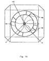
- Figure 1 and 1A show the preferred embodiment of the wind turbine (8) having a shaft (1) that is turned by rotor blades (2) that are attached to a top rotor cage plate (3) and bottom rotor cage plate (4) then drive an energy-transfer element (11) and an energy-utilizing device (12) (both shown as contained within or at the base).
- the height of these rotor blades in one of the preferred embodiments is 1.42 m (4 feet 8 inches) but will vary proportionally with the size of the unit built.
- the rotor blades are at least 6 m (20 feet) high by 6 m (20) (feet) in diameter.
- wind is compressed and directed to the rotor blades (2) by numerous stator blades (5) which can also be constructed of light weight materials such as those described above. Wind with a downward diagonal thrust can be accommodated by the rotor blades (2) through use of an open stator cage cover (10) that renders the turbine (8) at least partially topless and increases efficiency by up to an estimated 20% over any prior art. Wind attempting to enter the turbine (8) against the prevailing wind direction and hence against the direction of the rotors is deflected by top shield (6).
- Top shield (6) has a central pivoting point and an outer terminus and moves about the open top of turbine (8) by use of a center bearing (10A) side bearings (10B) and bearing race (10C). The movement of the top shield (6) to a downwind position is aided by the top shield vane (7).
- Figure 1B depicts a second embodiment of the present invention wherein top shield (6) is not provided with a vane.
- the top shield (6) creates an area on the downwind side of the turbine (8) that is of low turbidity and increases the invention's ability to exhaust wind passing through the machine.
- the top shield (6) does not at any time hinder the accommodation of productive winds from any direction.
- the described elements are made using light materials as hereinbefore described.
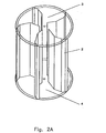
- Figure 2 and 2A show the rotor cage. Total rigidity and structural integrity may be enhanced by the top rotor cage plate (3) and the bottom rotor cage plate (4).
- top plate (3) may be arced slightly to better compress and direct air or other fluid into the rotor cage.
- a reverse angle on the bottom rotor cage plate (4) may accomplish the same task but with an upward thrust.
- top and bottom rotor cage plates may be attached to the shaft. This unique aspect can aid in the invention's ability to readily accept, utilize and exhaust wind or other fluid. Structural integrity and rigidity may be enhanced by the rotor blades being attached in two places rather than directly to the shaft as in previous art.
- Figure 3 shows the layout of the rotor blades (2) with respect to each other as well as to the shaft (1).
- This space is a substantial component of one embodiment of the invention in a number of ways.
- the space between the shaft and rotor can also achieve greater torque by pushing the kinetic energy of the wind to be exerted further away from the center point (i.e., the shaft).
- the flat surfaces of the rotor blades allow wind to impart its force and be immediately deflected.
- a curved or cupped surface may allow air to collect in the curvature and cushion the force of subsequent winds.
- the layout of the rotor cage in the preferred embodiment is shown but it must be mentioned that changes may be made to the layout without departing from the broad aspect of the present invention.
- the deflected air from the rotor blades is also able to find its way through the space between the shaft and the rotor blades to aid in the invention's ability to exhaust.
- the space between the rotor blades and the shaft in the preferred embodiment vary proportionately with the size of the unit built.
- stator blades (5) are arranged around the circumference of the rotor cage in equidistant pairs.
- 8 blades are shown but more or fewer blades could be used without substantially departing from the broad aspect of the present invention.
- straight stators that are offset from the center point allows air to enter the turbine with less turbidity and thus more force.
- the force of the wind may be greatly diminished.
- Straight stators while directing air into the invention, can have, a minimal effect on the loss of kinetic energy.
- Stator blade offset angles of from 30° to 60° by increments of 1° have been tested, and it has been found that the optimal angle of offset from the center point for the stator blades is 45°. Changing this angle by as much as 1° can seriously degrade the performance of the turbine. For example, tests have shown that in a 17.9 m/s (40 mph) wind, angling the stator blades at 44° will produce 200 kW less power over a 24 hour period than stator blades angled at 45°.
- the wind turbine has been designed to accept all available winds regardless of their speed and thus has no need for a stator design that would dampen or lessen the force of the wind.
- Figure 5 depicts the alignment of the stator cage cover. This is the part of the invention that allows the turbine to be virtually topless with regard to incoming currents of air. Once properly attached to the stator blades, the turbine is structurally sound and is ready to withstand, with regard to wind turbine embodiments, winds in excess of 44.7 m/s (100 m.p.h). Air currents approaching the rotor cage that have a slightly downward thrust pass through the open top (between the bearing races) and impact the rotor blades creating rotation. Previous art was able to accommodate wind currents that moved horizontally only, and thus, were able to accommodate only a portion of the wind that can be handled by the new invention.
- the stator cage cover may be constructed concentric braces to ensure structural stability. On the top side of the concentric braces are bearing races to accommodate the top shield bearings.
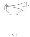
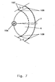
- Figures 6 and 7 show the top shield and top shield vane.
- the vane can be designed to create enough drag to rotate the top shield to a downwind position.
- Figure 1B depicts a second, alternative embodiment wherein the vane technique is not incorporated.
- the top shield prevents conflicting winds from entering the invention from the downwind side that would interfere with rotation or exhausting.
- the space between the top shield and the rotor cage can create a space of calm air that may improve the invention's exhausting characteristics and that has a dampening feature.
- the front side or upwind or upcurrent side of the top shield is slightly convex on the horizontal plane and may prevent the top shield from buffeting during periods of high winds.
- the center bearing (10A) of the top shield (6) can allow the mechanism to pivot easily while wheels or bearings (10B) resting on the concentric bearing races (10C) may carry the weight of the top shield.
- the wind vane or tail of the top shield (7) can aid in the top shield's ability to move into a position opposing the wind and may enhance the shield's stability during operation.
- the overall weight of the components can be an integral part of the invention. While mass (i.e., weight) can be used to dampen or deaden vibration, the new invention operates so smoothly that the lightweight carbon fiber materials used in its construction will not jeopardize structural integrity and will allow the turbine to be placed atop existing buildings or in environmentally sensitive areas or areas where large erection equipment would have no access.
- the basic concepts of the present invention may be embodied in a variety of ways within the scope of the appended claims. It involves the use of light weight materials in the construction of wind turbines and both the enhanced harnessing of kinetic energy techniques resulting from the use of light weight construction material as well as devices to accomplish the appropriate harnessing of energy.
- the harnessing techniques are disclosed as part of the results shown to be achieved by the various devices described, including turbine systems, and as steps which are inherent to utilization. They are simply the natural result of utilizing the devices as intended and described.
Landscapes
- Engineering & Computer Science (AREA)
- Life Sciences & Earth Sciences (AREA)
- Sustainable Development (AREA)
- Sustainable Energy (AREA)
- Chemical & Material Sciences (AREA)
- Combustion & Propulsion (AREA)
- Mechanical Engineering (AREA)
- General Engineering & Computer Science (AREA)
- Wind Motors (AREA)
- Connection Of Motors, Electrical Generators, Mechanical Devices, And The Like (AREA)
Claims (15)
- Turbine éolienne légère tournant verticalement améliorée (8) présentant une conversion améliorée de l'énergie cinétique du vent en énergie utilisable, comprenant:a. une base ayant une surface inférieure définissant une zone et une surface supérieure définissant une zone, dans laquelle ladite zone de ladite surface inférieure est supérieure à ladite zone de ladite surface supérieure et dans laquelle ladite surface supérieure comprend un élément de transfert d'énergie (11) et dans laquelle ladite base comprend une base conique ayant un angle permettant de diriger les courants de vent en douceur ;b. un arbre tournant verticalement (1) avec une extrémité supérieure et une extrémité inférieure, dans lesquelles ladite extrémité inférieure est mécaniquement connectée audit élément de transfert d'énergie (11) ;c. un dispositif utilisant de l'énergie (12) sensible audit arbre à travers ledit élément de transfert (11) de la surface supérieure de ladite base ;d. une plaque supérieure (3) fixée audit arbre tournant verticalement (1) ;e. une plaque inférieure (4) qui définit un diamètre et est fixée audit arbre tournant verticalement (1) ;f. une pluralité d'éléments générateurs de couple plats orientés verticalement (2), ayant des bords extérieurs et des bords intérieurs qui sont localisés circonférentiellement autour dudit arbre tournant verticalement (1) au niveau d'un espace entre ladite plaque supérieure (3) et ladite plaque inférieure (4) et sont fixés à l'intérieur de ladite plaque supérieure (3) et de ladite plaque inférieure (4) à leurs extrémités pour former un ensemble de cage ;g. une pluralité d'éléments directeurs de vent plats orientés verticalement (5) disposés circonférentiellement autour dudit ensemble de cage et adjacents auxdits bords extérieurs desdits éléments de génération de couple plats orientés verticalement (2) ;h. une couverture ouverte (10) comprenant des entretoisements concentriques ; eti. un bouclier supérieur (6) ayant un point pivotant central avec un terminal extérieur au dessus desdits entretoisements concentriques au-dessus dudit couvercle ouvert (10),amélioration dans laquelle les éléments générateurs de couple et directeurs de vent (2, 5) de la turbine éolienne sont réalisés à partir de matériaux légers qui permettent une conversion améliorée de l'énergie cinétique du vent en énergie mécanique par la turbine éolienne (8), dans laquelle lesdits matériaux légers comprennent des panneaux sandwich comprenant au moins deux couches de face extérieure (22) et un coeur en nid d'abeille (20, 21) qui les relie, de sorte que les cellules du coeur en nid d'abeille (20, 21) s'étendent sensiblement perpendiculairement aux couches de face (22).
- Turbine éolienne tournant verticalement améliorée (8), comme défini dans la revendication 1, dans laquelle le matériau léger est un matériau non-métallique.
- Turbine éolienne tournant verticalement améliorée (8), comme défini dans la revendication 1, dans laquelle ledit bouclier supérieur (6) comprend en outre un bouclier aspirant éolien contre les courants de vent contre-dominants.
- Turbine éolienne tournant verticalement améliorée (8), comme défini dans la revendication 1, comprenant en outre une aube de bouclier supérieur (7) dans laquelle ledit bouclier supérieur (6) est sensible à ladite aube de bouclier supérieur (7).
- Turbine éolienne tournant verticalement améliorée (8), comme défini dans la revendication 1, dans laquelle lesdits éléments de direction du vent plats (5) sont chacun décalés d'un angle d'environ 45° par rapport à un point central défini par l'arbre tournant verticalement (1).
- Turbine éolienne tournant verticalement améliorée (8), comme défini dans la revendication 1, dans laquelle ledit arbre tournant verticalement (1) est sensible audit ensemble de cage et tourne passivement.
- Turbine éolienne tournant verticalement améliorée (8), comme défini dans la revendication 1, dans laquelle chacune desdites pluralités d'éléments de génération de couple orientés verticalement (2) est seulement fixée à une plaque supérieure ronde (3) et une plaque inférieure ronde (4) à ses extrémités pour former ledit ensemble de cage.
- Turbine éolienne tournant verticalement améliorée (8), comme défini dans la revendication 7, dans laquelle chacun des éléments de génération de couple (2) a au moins trois surfaces orientées différemment.
- Turbine éolienne tournant verticalement améliorée (8), comme défini dans la revendication 1, dans laquelle lesdits éléments de direction du vent plats (5) sont fixés à ladite base par paires équidistantes.
- Turbine éolienne tournant verticalement améliorée (8), comme défini dans la revendication 1, dans laquelle ledit couvercle ouvert (10) comprend un couvercle de cage de stator ouvert.
- Turbine éolienne tournant verticalement améliorée (8), comme défini dans la revendication 10, dans laquelle ledit couvercle de cage de stator ouvert comprend des voies de roulements concentriques qui ont un roulement central et deux roulements latéraux circulaires.
- Turbine éolienne tournant verticalement améliorée (8), comme défini dans la revendication 1, dans laquelle ladite turbine éolienne (8) comprend une turbine verticale à axe long qui est une turbine omni-courant.
- Turbine éolienne tournant verticalement améliorée (8), comme défini dans la revendication 1, dans laquelle le coeur en nid d'abeille est fabriqué à partir de fibres de carbone non métalliques ou d'aluminium.
- Turbine éolienne tournant verticalement améliorée (8), comme défini dans la revendication 1, dans laquelle le bouclier supérieur (6) est un bouclier supérieur d'amortissement au dessus dudit couvercle ouvert (10) ayant un point de pivot central et une surface latérale avant convexe avec un terminal extérieur au dessus desdits entretoisements concentriques au dessus dudit couvercle ouvert (10).
- Turbine éolienne légère tournant verticalement améliorée (8), selon la revendication 1, ayant une conversion améliorée d'énergie cinétique du vent en une énergie utilisable, caractérisée en ce quea. ladite plaque supérieure (3) est ronde et est fixée à proximité de l'extrémité supérieure dudit arbre tournant verticalement ;b. ladite plaque inférieure (4) est ronde et est fixée audit arbre tournant verticalement (1) à un emplacement au dessus de la surface supérieure de ladite base ;c. et ledit couvercle ouvert (10) comprenant des entretoisements concentriques comprenant deux roulements latéraux.
Applications Claiming Priority (3)
| Application Number | Priority Date | Filing Date | Title |
|---|---|---|---|
| US923043 | 1992-07-31 | ||
| US09/923,043 US6538340B2 (en) | 2001-08-06 | 2001-08-06 | Wind turbine system |
| PCT/US2001/030010 WO2003014564A1 (fr) | 2001-08-06 | 2001-09-26 | Eolienne |
Publications (3)
| Publication Number | Publication Date |
|---|---|
| EP1432910A1 EP1432910A1 (fr) | 2004-06-30 |
| EP1432910A4 EP1432910A4 (fr) | 2005-11-02 |
| EP1432910B1 true EP1432910B1 (fr) | 2006-11-22 |
Family
ID=25448018
Family Applications (1)
| Application Number | Title | Priority Date | Filing Date |
|---|---|---|---|
| EP01975376A Expired - Lifetime EP1432910B1 (fr) | 2001-08-06 | 2001-09-26 | Eolienne |
Country Status (10)
| Country | Link |
|---|---|
| US (1) | US6538340B2 (fr) |
| EP (1) | EP1432910B1 (fr) |
| CN (1) | CN1292167C (fr) |
| AT (1) | ATE346235T1 (fr) |
| AU (1) | AU2001294710B2 (fr) |
| DE (1) | DE60124788T2 (fr) |
| GE (1) | GEP20063893B (fr) |
| RU (1) | RU2279567C2 (fr) |
| UA (1) | UA76188C2 (fr) |
| WO (1) | WO2003014564A1 (fr) |
Families Citing this family (74)
| Publication number | Priority date | Publication date | Assignee | Title |
|---|---|---|---|---|
| CN1249340C (zh) * | 2001-04-12 | 2006-04-05 | 黄建文 | 集风式风力发电方法与设备 |
| WO2004011798A2 (fr) * | 2002-07-31 | 2004-02-05 | The Board Of Trustees Of The University Of Illinois | Dispositif de turbine a vent |
| US6841894B2 (en) * | 2003-01-02 | 2005-01-11 | Josep Lluis Gomez Gomar | Wind power generator having wind channeling body with progressively reduced section |
| US7759812B2 (en) | 2003-04-30 | 2010-07-20 | Terra Moya Aqua, Inc. | Integrated power plant that utilizes renewable and alternative energy sources |
| WO2004099605A2 (fr) * | 2003-04-30 | 2004-11-18 | Taylor Ronald J | Eolienne a deflecteur arretant et dirigeant le vent et rotors avec ou sans puits central |
| US7189050B2 (en) * | 2003-04-30 | 2007-03-13 | Terra Moya Aqua, Inc. | Cross-flow wind turbine |
| US6981839B2 (en) * | 2004-03-09 | 2006-01-03 | Leon Fan | Wind powered turbine in a tunnel |
| CA2452967A1 (fr) * | 2003-12-31 | 2005-06-30 | Bud T. J. Johnson | Configuration de moteur a turbine-deflecteur spherique actionnes par l'energie eolienne |
| CA2452965A1 (fr) * | 2003-12-31 | 2005-06-30 | Bud T. J. Johnson | Configuration de moteur a turbine-rotor horizontal actionnes par l'energie eolienne |
| US20050230980A1 (en) * | 2004-04-15 | 2005-10-20 | Andre Brunet | Wind turbine mounted on power transmission tower |
| CA2467199A1 (fr) * | 2004-05-19 | 2005-11-19 | Bud T.J. Johnson | Eolienne |
| US7214029B2 (en) * | 2004-07-01 | 2007-05-08 | Richter Donald L | Laminar air turbine |
| US7172386B2 (en) * | 2004-08-05 | 2007-02-06 | Minh-Hoang Dinh Truong | Wind and solar power plant with variable high speed rotor trains |
| EP2302172A1 (fr) | 2004-11-12 | 2011-03-30 | Board of Trustees of Michigan State University | Machine comprenant un rotor tissé électromagnétique et procédé de fabrication |
| US7215037B2 (en) * | 2004-11-19 | 2007-05-08 | Saverio Scalzi | Protective wind energy conversion chamber |
| US7182573B2 (en) * | 2004-11-24 | 2007-02-27 | Stanley Jonsson | Wind turbine |
| US7633177B2 (en) * | 2005-04-14 | 2009-12-15 | Natural Forces, Llc | Reduced friction wind turbine apparatus and method |
| US7329965B2 (en) * | 2005-06-03 | 2008-02-12 | Novastron Corporation | Aerodynamic-hybrid vertical-axis wind turbine |
| WO2007012200A1 (fr) * | 2005-07-25 | 2007-02-01 | The University Of Manitoba | Systeme de conception de tours eoliennes composites |
| US20070029807A1 (en) * | 2005-08-08 | 2007-02-08 | Clayton Kass | Methods and systems for generating wind energy |
| WO2007048001A2 (fr) * | 2005-10-20 | 2007-04-26 | Reidy Michael T | Appareils, systèmes, procédés et améliorations pour exploiter l’énergie éolienne |
| US20070104934A1 (en) * | 2005-11-10 | 2007-05-10 | General Electric Company | Lightweight nacelle for turbines and methods for making same |
| US7323791B2 (en) * | 2006-03-27 | 2008-01-29 | Jonsson Stanley C | Louvered horizontal wind turbine |
| US7385302B2 (en) * | 2006-06-27 | 2008-06-10 | Jonsson Stanley C | Wind turbine having variable pitch airfoils |
| US7550865B2 (en) * | 2006-06-27 | 2009-06-23 | Jonsson Stanley C | Wind turbine having variable pitch airfoils that close when moving against the direction of the wind |
| WO2008045662A2 (fr) * | 2006-10-10 | 2008-04-17 | Adaptide, Inc. | Dispositif adaptatif d'extraction de l'énergie des courants de marée |
| CN101583792B (zh) | 2006-12-04 | 2013-02-13 | 设计许可国际集团有限公司 | 风轮机设备 |
| RU2330180C1 (ru) * | 2007-02-26 | 2008-07-27 | Военная академия Ракетных войск стратегического назначения имени Петра Великого | Воздушный двигатель |
| US7521816B2 (en) * | 2007-03-01 | 2009-04-21 | Helfrich Jim C | Water current powered motor |
| EA012718B1 (ru) * | 2007-09-26 | 2009-12-30 | Игорь Владимирович ПРУС | Многоуровневое жилое здание со встроенной автомобильной стоянкой |
| US8087894B2 (en) * | 2007-10-09 | 2012-01-03 | Franklin Charles Brooks | Aperture and flap vertical axis wind machine |
| ES2338835B1 (es) | 2007-10-16 | 2011-02-18 | Salvador Domenech Barcons | Dispositivo generador de fuerza motriz. |
| WO2009094602A1 (fr) * | 2008-01-24 | 2009-07-30 | Knutson Roger C | Éolienne à axes multiples avec aile concentratrice d'énergie |
| WO2009117131A1 (fr) * | 2008-03-20 | 2009-09-24 | Environmental Products Of Minnesota | Turbine à axe vertical pour générer de l'énergie éolienne |
| US8070449B2 (en) * | 2008-04-29 | 2011-12-06 | Absolute Turn, Inc. | Wind turbine |
| CN102057157B (zh) * | 2008-05-07 | 2016-06-29 | 设计许可国际集团有限公司 | 风力涡轮机 |
| US7969036B2 (en) * | 2008-05-22 | 2011-06-28 | Chun-Neng Chung | Apparatus for generating electric power using wind energy |
| AU2009260465B2 (en) * | 2008-05-28 | 2014-09-25 | Stephen David Boyd | Wind diverter |
| US7863765B2 (en) * | 2008-07-07 | 2011-01-04 | Fu-Hung Yang | Vertical shaft type windmill with arcuate hook shaped vane blades |
| US20100098542A1 (en) * | 2008-10-20 | 2010-04-22 | Jonsson Stanley C | Wind Turbine Having Two Sets of Air Panels to Capture Wind Moving in Perpendicular Direction |
| US7874787B2 (en) * | 2009-01-30 | 2011-01-25 | Richard Morris | Vertical axis wind turbine system |
| RU2390654C1 (ru) * | 2009-04-24 | 2010-05-27 | Валерий Петрович Вигаев | Ветроэнергетическая установка |
| WO2010123400A1 (fr) * | 2009-04-24 | 2010-10-28 | МИХОВ, Александр Петрович | Installation éolienne |
| CN101943109A (zh) * | 2009-07-03 | 2011-01-12 | 无锡爱尼达新能源科技有限公司 | 垂直轴风力发电机的螺旋形桨叶 |
| BRPI0904411A2 (pt) * | 2009-07-15 | 2011-03-15 | Nadilton De Souza Monteiro | turbina eólica flutuante de eixo vertical |
| WO2011026210A1 (fr) * | 2009-09-02 | 2011-03-10 | Nadilton De Souza Monteiro | Éolienne verticale destinée à être utilisée en haute mer |
| US8424805B2 (en) | 2009-10-07 | 2013-04-23 | Donald Smith | Airfoil structure |
| US20110158787A1 (en) | 2010-03-15 | 2011-06-30 | Thacker Ii Andrew Carlton | Wind turbine |
| BRPI1001891A2 (pt) * | 2010-06-01 | 2012-03-06 | Entel Engenharia E Tecnologia Ltda | Turbina eólica de eixo vertical |
| AT510238B1 (de) | 2010-07-27 | 2012-06-15 | Mario Kinelly | Rotor für ein windrad |
| US7976267B2 (en) | 2010-08-10 | 2011-07-12 | Burrell Iv James W | Helix turbine system and energy production means |
| US20120074701A1 (en) * | 2010-09-24 | 2012-03-29 | Frank Hernandez | Ridge cap wind generation system |
| CN102562467B (zh) * | 2010-12-29 | 2014-08-06 | 孙立蓉 | 聚风增速风力发电装置 |
| WO2012094336A2 (fr) * | 2011-01-03 | 2012-07-12 | Roter Samuel | Capture d'écoulement fluidique et appareil d'accélération pour hyper-conversion |
| FI20115536L (fi) * | 2011-05-31 | 2013-03-25 | Teknologian Tutkimuskeskus Vtt Oy | Tuuliturbiinin siipi ja tähän liittyvä valmistusmenetelmä |
| FR2976324B1 (fr) * | 2011-06-09 | 2017-11-17 | Michel Raffin | Nouveau concept de station de transfert d'energie. |
| CN102374131B (zh) * | 2011-09-28 | 2013-07-31 | 上海庆华蜂巢建材有限公司 | 一种蜂巢板制成的垂直轴风力发电机 |
| RU2492354C1 (ru) * | 2011-12-29 | 2013-09-10 | Андрей Викторович Темеров | Профиль для изготовления вертикальных лопастей для вертикально-осевых ветрогенераторных установок |
| US9752555B2 (en) | 2012-04-26 | 2017-09-05 | Ronald GDOVIC | Self-starting savonius wind turbine |
| AU2013313031B2 (en) * | 2012-09-07 | 2018-06-21 | Csr Building Products Limited | Rotor ventilator |
| US10193430B2 (en) | 2013-03-15 | 2019-01-29 | Board Of Trustees Of Michigan State University | Electromagnetic device having discrete wires |
| US8779620B1 (en) * | 2013-07-31 | 2014-07-15 | Joseph Mele | Rotary windmill power generator |
| RU2550993C2 (ru) * | 2013-08-08 | 2015-05-20 | Евгений Владимирович Житний | Ветродвигатель |
| EP2876900A1 (fr) | 2013-11-25 | 2015-05-27 | Oticon A/S | Banc de filtrage spatial pour système auditif |
| CN105020104A (zh) * | 2015-06-10 | 2015-11-04 | 河海大学 | 海上漂浮式风力机平台智能减振装置 |
| US10612515B2 (en) * | 2015-06-25 | 2020-04-07 | Dme Wind Energy Corporation | Vertical axis wind turbine |
| US10704532B2 (en) | 2016-04-14 | 2020-07-07 | Ronald GDOVIC | Savonius wind turbines |
| CN107575343A (zh) * | 2017-10-26 | 2018-01-12 | 中能金瀚能源技术有限公司 | 由垂直轴风力发电机瓦形风叶组成的正弓形风叶阵列 |
| CA2997766C (fr) * | 2018-03-08 | 2019-10-08 | Branko Mizerit | Tour d'eolienne a acceleration de tourbillon |
| CN108266880B (zh) * | 2018-03-23 | 2024-01-26 | 四川长虹空调有限公司 | 一种空调新型出风护罩 |
| FR3087854A1 (fr) * | 2018-10-29 | 2020-05-01 | Claude Sigrand | Dispositif de securite passive pour permettre l’installation en serie d’eolienne a axe vertical le long des autoroutes |
| WO2021119772A1 (fr) * | 2019-12-21 | 2021-06-24 | Carlos Gomes | Éolienne à axe vertical avec transmission par axe de torsion flexible |
| CN113027673A (zh) * | 2021-04-16 | 2021-06-25 | 安徽明玑电力设备有限公司 | 一种垂直轴风力发电机系统 |
| LT6877B (lt) * | 2021-05-10 | 2021-12-27 | SELEZNIOVAS Aleksandras | Vėjo srautu veikiamas įrenginys |
Family Cites Families (20)
| Publication number | Priority date | Publication date | Assignee | Title |
|---|---|---|---|---|
| US4224528A (en) * | 1979-05-14 | 1980-09-23 | Argo William H | Solar thermal and wind energy power source |
| US4318019A (en) * | 1980-05-09 | 1982-03-02 | Teasley Granvil E | Alternator for wind generator |
| US4457666A (en) * | 1982-04-14 | 1984-07-03 | The Windgrabber Corporation | Apparatus and method for deriving energy from a moving gas stream |
| US4494007A (en) * | 1982-09-02 | 1985-01-15 | Gaston Manufacturing, Inc. | Wind machine |
| US4545729A (en) * | 1983-07-28 | 1985-10-08 | Joe Storm | Wind turbine apparatus |
| SU1486623A1 (ru) * | 1985-04-24 | 1989-06-15 | Kh Aviatsionnyj Institut | Ветроколесо |
| GB8626347D0 (en) * | 1986-11-04 | 1986-12-03 | Bicc Plc | Wind energy convertor |
| DE3828361A1 (de) * | 1988-08-20 | 1990-02-22 | Johannes Sieberns | Windstaerkenabhaengig gesteuerte um die vertikalachse drehende windkraftanlage mit festen und beweglichen rotorblaettern |
| SU1657722A1 (ru) * | 1989-06-26 | 1991-06-23 | Харьковский авиационный институт им.Н.Е.Жуковского | Ветродвигатель |
| GR910200234U (en) * | 1990-05-31 | 1992-07-30 | Mihail Valsamidis | Turbine wind machine with a vertical axis |
| US5038049A (en) * | 1990-09-12 | 1991-08-06 | Shuichi Kato | Vertical axis wind powered generator |
| AU5016493A (en) * | 1992-08-18 | 1994-03-15 | Four Winds Energy Corporation | Wind turbine particularly suited for high-wind conditions |
| US5852331A (en) * | 1996-06-21 | 1998-12-22 | Giorgini; Roberto | Wind turbine booster |
| RU2165034C2 (ru) * | 1996-10-15 | 2001-04-10 | Майед Эль Марри Сакр | Ветряной двигатель с вращением вокруг вертикальной оси |
| US6097104A (en) * | 1999-01-19 | 2000-08-01 | Russell; Thomas H. | Hybrid energy recovery system |
| US6191496B1 (en) * | 1998-12-01 | 2001-02-20 | Dillyn M. Elder | Wind turbine system |
| US6448669B1 (en) * | 1998-12-01 | 2002-09-10 | Dillyn M. Elder | Water power generation system |
| US6448668B1 (en) * | 1999-06-30 | 2002-09-10 | Armand Robitaille | Vertical-axis wind mill supported by a fluid |
| RU2168059C2 (ru) * | 1999-07-27 | 2001-05-27 | Баранов Александр Николаевич | Ветродвигатель |
| US6320273B1 (en) * | 2000-02-12 | 2001-11-20 | Otilio Nemec | Large vertical-axis variable-pitch wind turbine |
-
2001
- 2001-08-06 US US09/923,043 patent/US6538340B2/en not_active Expired - Fee Related
- 2001-09-26 GE GE5544A patent/GEP20063893B/en unknown
- 2001-09-26 DE DE60124788T patent/DE60124788T2/de not_active Expired - Fee Related
- 2001-09-26 AT AT01975376T patent/ATE346235T1/de not_active IP Right Cessation
- 2001-09-26 EP EP01975376A patent/EP1432910B1/fr not_active Expired - Lifetime
- 2001-09-26 WO PCT/US2001/030010 patent/WO2003014564A1/fr not_active Ceased
- 2001-09-26 CN CNB01823691XA patent/CN1292167C/zh not_active Expired - Fee Related
- 2001-09-26 UA UA2004031663A patent/UA76188C2/uk unknown
- 2001-09-26 RU RU2004106624/06A patent/RU2279567C2/ru not_active IP Right Cessation
- 2001-09-26 AU AU2001294710A patent/AU2001294710B2/en not_active Ceased
Also Published As
| Publication number | Publication date |
|---|---|
| RU2004106624A (ru) | 2005-03-27 |
| EP1432910A4 (fr) | 2005-11-02 |
| EP1432910A1 (fr) | 2004-06-30 |
| US20030025335A1 (en) | 2003-02-06 |
| UA76188C2 (en) | 2006-07-17 |
| CN1292167C (zh) | 2006-12-27 |
| DE60124788D1 (de) | 2007-01-04 |
| RU2279567C2 (ru) | 2006-07-10 |
| ATE346235T1 (de) | 2006-12-15 |
| US6538340B2 (en) | 2003-03-25 |
| DE60124788T2 (de) | 2007-09-13 |
| HK1074236A1 (en) | 2005-11-04 |
| WO2003014564A1 (fr) | 2003-02-20 |
| GEP20063893B (en) | 2006-08-10 |
| CN1558988A (zh) | 2004-12-29 |
| AU2001294710B2 (en) | 2007-09-20 |
Similar Documents
| Publication | Publication Date | Title |
|---|---|---|
| US6538340B2 (en) | Wind turbine system | |
| US6191496B1 (en) | Wind turbine system | |
| US6448669B1 (en) | Water power generation system | |
| AU2001294710A1 (en) | Wind turbine system | |
| US5391926A (en) | Wind turbine particularly suited for high-wind conditions | |
| AU749851B2 (en) | Wind turbine | |
| US7315093B2 (en) | Wind turbine system for buildings | |
| US7172386B2 (en) | Wind and solar power plant with variable high speed rotor trains | |
| US8157501B2 (en) | Vertical axis sail-type windmill power transfer device | |
| Schubel et al. | Wind turbine blade design review | |
| US7802967B2 (en) | Vertical axis self-breaking wind turbine | |
| US11236724B2 (en) | Vertical axis wind turbine | |
| US20100171314A1 (en) | Vertically Oriented Wind Tower Generator | |
| Óskarsdóttir | A general description and comparison of horizontal axis wind turbines and vertical axis wind turbines | |
| CN103939291B (zh) | 高低风速兼容型风电机组 | |
| CN101539108A (zh) | 一种双电机聚压式风力发电装置 | |
| Zoucha et al. | Review of recent patents on vertical-axis wind turbines (VAWTs) | |
| CN100453803C (zh) | 屋顶风力发电装置 | |
| CN101749179A (zh) | 一种用于垂直轴风力发电机的整流增速塔 | |
| WO2012050540A1 (fr) | Éolienne (réalisations) | |
| NZ531579A (en) | Vertically rotating wind turbine system | |
| Lim et al. | Advanced wind turbines | |
| HK1074236B (en) | Wind turbine system | |
| AU2007100123A4 (en) | Vetical axis wing turbine | |
| JP2024509551A (ja) | 風力発電設備 |
Legal Events
| Date | Code | Title | Description |
|---|---|---|---|
| PUAI | Public reference made under article 153(3) epc to a published international application that has entered the european phase |
Free format text: ORIGINAL CODE: 0009012 |
|
| 17P | Request for examination filed |
Effective date: 20040305 |
|
| AK | Designated contracting states |
Kind code of ref document: A1 Designated state(s): AT BE CH CY DE DK ES FI FR GB GR IE IT LI LU MC NL PT SE TR |
|
| AX | Request for extension of the european patent |
Extension state: AL LT LV MK RO SI |
|
| A4 | Supplementary search report drawn up and despatched |
Effective date: 20050916 |
|
| GRAP | Despatch of communication of intention to grant a patent |
Free format text: ORIGINAL CODE: EPIDOSNIGR1 |
|
| GRAS | Grant fee paid |
Free format text: ORIGINAL CODE: EPIDOSNIGR3 |
|
| GRAA | (expected) grant |
Free format text: ORIGINAL CODE: 0009210 |
|
| AK | Designated contracting states |
Kind code of ref document: B1 Designated state(s): AT BE CH CY DE DK ES FI FR GB GR IE IT LI LU MC NL PT SE TR |
|
| AX | Request for extension of the european patent |
Extension state: AL LT LV MK RO SI |
|
| PG25 | Lapsed in a contracting state [announced via postgrant information from national office to epo] |
Ref country code: IT Free format text: LAPSE BECAUSE OF FAILURE TO SUBMIT A TRANSLATION OF THE DESCRIPTION OR TO PAY THE FEE WITHIN THE PRESCRIBED TIME-LIMIT;WARNING: LAPSES OF ITALIAN PATENTS WITH EFFECTIVE DATE BEFORE 2007 MAY HAVE OCCURRED AT ANY TIME BEFORE 2007. THE CORRECT EFFECTIVE DATE MAY BE DIFFERENT FROM THE ONE RECORDED. Effective date: 20061122 Ref country code: BE Free format text: LAPSE BECAUSE OF FAILURE TO SUBMIT A TRANSLATION OF THE DESCRIPTION OR TO PAY THE FEE WITHIN THE PRESCRIBED TIME-LIMIT Effective date: 20061122 Ref country code: NL Free format text: LAPSE BECAUSE OF FAILURE TO SUBMIT A TRANSLATION OF THE DESCRIPTION OR TO PAY THE FEE WITHIN THE PRESCRIBED TIME-LIMIT Effective date: 20061122 Ref country code: LI Free format text: LAPSE BECAUSE OF FAILURE TO SUBMIT A TRANSLATION OF THE DESCRIPTION OR TO PAY THE FEE WITHIN THE PRESCRIBED TIME-LIMIT Effective date: 20061122 Ref country code: CH Free format text: LAPSE BECAUSE OF FAILURE TO SUBMIT A TRANSLATION OF THE DESCRIPTION OR TO PAY THE FEE WITHIN THE PRESCRIBED TIME-LIMIT Effective date: 20061122 Ref country code: FI Free format text: LAPSE BECAUSE OF FAILURE TO SUBMIT A TRANSLATION OF THE DESCRIPTION OR TO PAY THE FEE WITHIN THE PRESCRIBED TIME-LIMIT Effective date: 20061122 |
|
| REG | Reference to a national code |
Ref country code: GB Ref legal event code: FG4D |
|
| REG | Reference to a national code |
Ref country code: CH Ref legal event code: EP |
|
| REG | Reference to a national code |
Ref country code: IE Ref legal event code: FG4D |
|
| REF | Corresponds to: |
Ref document number: 60124788 Country of ref document: DE Date of ref document: 20070104 Kind code of ref document: P |
|
| PG25 | Lapsed in a contracting state [announced via postgrant information from national office to epo] |
Ref country code: SE Free format text: LAPSE BECAUSE OF FAILURE TO SUBMIT A TRANSLATION OF THE DESCRIPTION OR TO PAY THE FEE WITHIN THE PRESCRIBED TIME-LIMIT Effective date: 20070222 Ref country code: DK Free format text: LAPSE BECAUSE OF FAILURE TO SUBMIT A TRANSLATION OF THE DESCRIPTION OR TO PAY THE FEE WITHIN THE PRESCRIBED TIME-LIMIT Effective date: 20070222 |
|
| PG25 | Lapsed in a contracting state [announced via postgrant information from national office to epo] |
Ref country code: ES Free format text: LAPSE BECAUSE OF FAILURE TO SUBMIT A TRANSLATION OF THE DESCRIPTION OR TO PAY THE FEE WITHIN THE PRESCRIBED TIME-LIMIT Effective date: 20070305 |
|
| PG25 | Lapsed in a contracting state [announced via postgrant information from national office to epo] |
Ref country code: PT Free format text: LAPSE BECAUSE OF FAILURE TO SUBMIT A TRANSLATION OF THE DESCRIPTION OR TO PAY THE FEE WITHIN THE PRESCRIBED TIME-LIMIT Effective date: 20070423 |
|
| LTIE | Lt: invalidation of european patent or patent extension |
Effective date: 20061122 |
|
| NLV1 | Nl: lapsed or annulled due to failure to fulfill the requirements of art. 29p and 29m of the patents act | ||
| REG | Reference to a national code |
Ref country code: CH Ref legal event code: PL |
|
| EN | Fr: translation not filed | ||
| PLBE | No opposition filed within time limit |
Free format text: ORIGINAL CODE: 0009261 |
|
| STAA | Information on the status of an ep patent application or granted ep patent |
Free format text: STATUS: NO OPPOSITION FILED WITHIN TIME LIMIT |
|
| 26N | No opposition filed |
Effective date: 20070823 |
|
| REG | Reference to a national code |
Ref country code: GB Ref legal event code: 732E |
|
| PGFP | Annual fee paid to national office [announced via postgrant information from national office to epo] |
Ref country code: AT Payment date: 20070904 Year of fee payment: 7 Ref country code: TR Payment date: 20070905 Year of fee payment: 7 |
|
| PGFP | Annual fee paid to national office [announced via postgrant information from national office to epo] |
Ref country code: GB Payment date: 20070926 Year of fee payment: 7 |
|
| PGFP | Annual fee paid to national office [announced via postgrant information from national office to epo] |
Ref country code: DE Payment date: 20071031 Year of fee payment: 7 Ref country code: LU Payment date: 20071010 Year of fee payment: 7 |
|
| PG25 | Lapsed in a contracting state [announced via postgrant information from national office to epo] |
Ref country code: FR Free format text: LAPSE BECAUSE OF FAILURE TO SUBMIT A TRANSLATION OF THE DESCRIPTION OR TO PAY THE FEE WITHIN THE PRESCRIBED TIME-LIMIT Effective date: 20070713 Ref country code: GR Free format text: LAPSE BECAUSE OF FAILURE TO SUBMIT A TRANSLATION OF THE DESCRIPTION OR TO PAY THE FEE WITHIN THE PRESCRIBED TIME-LIMIT Effective date: 20070223 Ref country code: MC Free format text: LAPSE BECAUSE OF NON-PAYMENT OF DUE FEES Effective date: 20070930 |
|
| PG25 | Lapsed in a contracting state [announced via postgrant information from national office to epo] |
Ref country code: IE Free format text: LAPSE BECAUSE OF NON-PAYMENT OF DUE FEES Effective date: 20070926 |
|
| PG25 | Lapsed in a contracting state [announced via postgrant information from national office to epo] |
Ref country code: FR Free format text: LAPSE BECAUSE OF FAILURE TO SUBMIT A TRANSLATION OF THE DESCRIPTION OR TO PAY THE FEE WITHIN THE PRESCRIBED TIME-LIMIT Effective date: 20061122 |
|
| GBPC | Gb: european patent ceased through non-payment of renewal fee |
Effective date: 20080926 |
|
| PG25 | Lapsed in a contracting state [announced via postgrant information from national office to epo] |
Ref country code: CY Free format text: LAPSE BECAUSE OF FAILURE TO SUBMIT A TRANSLATION OF THE DESCRIPTION OR TO PAY THE FEE WITHIN THE PRESCRIBED TIME-LIMIT Effective date: 20061122 Ref country code: AT Free format text: LAPSE BECAUSE OF NON-PAYMENT OF DUE FEES Effective date: 20080926 Ref country code: DE Free format text: LAPSE BECAUSE OF NON-PAYMENT OF DUE FEES Effective date: 20090401 |
|
| PG25 | Lapsed in a contracting state [announced via postgrant information from national office to epo] |
Ref country code: GB Free format text: LAPSE BECAUSE OF NON-PAYMENT OF DUE FEES Effective date: 20080926 |
|
| PG25 | Lapsed in a contracting state [announced via postgrant information from national office to epo] |
Ref country code: LU Free format text: LAPSE BECAUSE OF NON-PAYMENT OF DUE FEES Effective date: 20080926 |
|
| PG25 | Lapsed in a contracting state [announced via postgrant information from national office to epo] |
Ref country code: TR Free format text: LAPSE BECAUSE OF NON-PAYMENT OF DUE FEES Effective date: 20100921 |
|
| PG25 | Lapsed in a contracting state [announced via postgrant information from national office to epo] |
Ref country code: TR Free format text: LAPSE BECAUSE OF NON-PAYMENT OF DUE FEES Effective date: 20080926 |