EP1432964B1 - Procede et dispositif d'alimentation de quantites dosees d'un materiau en vrac a grains fins - Google Patents
Procede et dispositif d'alimentation de quantites dosees d'un materiau en vrac a grains fins Download PDFInfo
- Publication number
- EP1432964B1 EP1432964B1 EP02774644A EP02774644A EP1432964B1 EP 1432964 B1 EP1432964 B1 EP 1432964B1 EP 02774644 A EP02774644 A EP 02774644A EP 02774644 A EP02774644 A EP 02774644A EP 1432964 B1 EP1432964 B1 EP 1432964B1
- Authority
- EP
- European Patent Office
- Prior art keywords
- bulk material
- dosing
- quantities
- chambers
- dosing chambers
- Prior art date
- Legal status (The legal status is an assumption and is not a legal conclusion. Google has not performed a legal analysis and makes no representation as to the accuracy of the status listed.)
- Expired - Lifetime
Links
- 239000013590 bulk material Substances 0.000 title claims abstract description 68
- 238000000034 method Methods 0.000 title claims abstract description 28
- 238000007599 discharging Methods 0.000 claims description 6
- 230000003213 activating effect Effects 0.000 claims 2
- 239000000843 powder Substances 0.000 description 11
- 239000012528 membrane Substances 0.000 description 4
- 230000006641 stabilisation Effects 0.000 description 4
- 238000011105 stabilization Methods 0.000 description 4
- 238000000576 coating method Methods 0.000 description 3
- 239000007788 liquid Substances 0.000 description 3
- 239000000203 mixture Substances 0.000 description 3
- 230000035515 penetration Effects 0.000 description 3
- 239000007787 solid Substances 0.000 description 3
- 238000002788 crimping Methods 0.000 description 2
- 238000010586 diagram Methods 0.000 description 2
- 230000009969 flowable effect Effects 0.000 description 2
- 238000005488 sandblasting Methods 0.000 description 2
- 238000005507 spraying Methods 0.000 description 2
- 239000000126 substance Substances 0.000 description 2
- 230000000903 blocking effect Effects 0.000 description 1
- 210000004556 brain Anatomy 0.000 description 1
- 239000011248 coating agent Substances 0.000 description 1
- 230000001419 dependent effect Effects 0.000 description 1
- 230000008021 deposition Effects 0.000 description 1
- 239000003814 drug Substances 0.000 description 1
- 238000009503 electrostatic coating Methods 0.000 description 1
- 238000009472 formulation Methods 0.000 description 1
- 239000000463 material Substances 0.000 description 1
- 230000000717 retained effect Effects 0.000 description 1
- 150000003839 salts Chemical class 0.000 description 1
- 238000007789 sealing Methods 0.000 description 1
- 238000000926 separation method Methods 0.000 description 1
- 239000000758 substrate Substances 0.000 description 1
- 238000003466 welding Methods 0.000 description 1
Images


Classifications
-
- G—PHYSICS
- G01—MEASURING; TESTING
- G01F—MEASURING VOLUME, VOLUME FLOW, MASS FLOW OR LIQUID LEVEL; METERING BY VOLUME
- G01F15/00—Details of, or accessories for, apparatus of groups G01F1/00 - G01F13/00 insofar as such details or appliances are not adapted to particular types of such apparatus
- G01F15/001—Means for regulating or setting the meter for a predetermined quantity
- G01F15/003—Means for regulating or setting the meter for a predetermined quantity using electromagnetic, electric or electronic means
-
- G—PHYSICS
- G01—MEASURING; TESTING
- G01F—MEASURING VOLUME, VOLUME FLOW, MASS FLOW OR LIQUID LEVEL; METERING BY VOLUME
- G01F11/00—Apparatus requiring external operation adapted at each repeated and identical operation to measure and separate a predetermined volume of fluid or fluent solid material from a supply or container, without regard to weight, and to deliver it
- G01F11/28—Apparatus requiring external operation adapted at each repeated and identical operation to measure and separate a predetermined volume of fluid or fluent solid material from a supply or container, without regard to weight, and to deliver it with stationary measuring chambers having constant volume during measurement
- G01F11/282—Apparatus requiring external operation adapted at each repeated and identical operation to measure and separate a predetermined volume of fluid or fluent solid material from a supply or container, without regard to weight, and to deliver it with stationary measuring chambers having constant volume during measurement for fluent solid material not provided for in G01F11/34, G01F11/40, G01F11/46
Definitions
- the invention relates to a method for feeding metered quantities of a fine-grained bulk material into a further working process according to the preamble of claim 1.
- a method of the type mentioned are, for example, from DE-A-199 59 473 known. These allow a pulsed or a continuous metering of a powdery substance, which is carried out by means of several small and precisely matched partial dosages.
- the size of the partial dosing is determined by the size of an alternately fillable and emptiable dosing chamber. For a total quantity to be dispensed in a given time unit, a suitable number and size of metering chambers is selected in advance, wherein three different metering chambers are available for selection in the bolt, for example. If a different dosing quantity is required, the dosing chambers must be replaced.
- the present invention has for its object to provide a method for supplying metered quantities of fine-grained bulk material, which allow a simpler, yet highly precise metering different large amounts of fine-grained bulk material.
- a machine device for automatic filling of a flowable product, in which a measuring chamber with an inlet and outlet connected to the funnel, which is respectively aligned on successive receptacles. Within the passage channel, an outlet valve is also arranged, which serves in the open state for conveying the specific amount of the flowable product as a whole into the receptacle. But there are not provided several metering chambers for a variable metering of the bulk material.
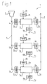
- Fig.1 schematically shows a device 1 for the pneumatic supply of metered amounts of a fine-grained bulk material, such as a powder, from a container 2 in a further working process (indicated by arrow 3).
- the container 2 may be, for example, a powder silo.
- powdered substances can be metered under or without pressure into a coating process such as cold gas spraying, electrostatic coating, rapid prototyping, plasma powder deposition welding, formulations such as mixtures of dye salts, or in chemistry, medicine, bakeries, etc. initiated become.
- the metered bulk material feed could also be used, for example, in sandblasting or other work processes.
- the bulk material is pneumatically conveyed from the container 2 via a central supply line 4 and via three supply lines 4a, 4b, 4c branching off to three metering chambers 5a, 5b, 5c, and from these in turn via a respective discharge line 6a opening into a central discharge line 6, 6b, 6c continued under pressure.
- each metering chamber 5a or 5b or 5c alternately connected to a suction or vacuum line 7a or 7b or 7c on the one hand and to a compressed gas line 8a or 8b or 8c on the other hand, wherein the connection to the suction or vacuum line 7a or 7b or 7c sucked the bulk material with negative pressure and the metering chamber 5a and 5b and 5c is filled, and when connecting to the compressed gas line 8a or 8b and 8c, the metering chamber 5a and 5b or 5c emptied and the bulk material is continued with overpressure or a vacuum.
- gas-permeable filter membranes while the penetration of the bulk material is avoided in the gas lines.
- valves 10a, 10b, 10c are present. Switching on and off the connection to the respective compressed gas line 8a, 8b, 8c also takes place via valves 11a, 11b, 11c.
- the bulk material supply lines 4 a, 4 b, 4 c to the individual metering chambers 5 a, 5 b, 5 c can each be closed or kept open by means of a valve 12 a, 12 b, 12 c.
- valves 13a, 13b, 13c are present.
- valves in the bulk and gas lines to the individual metering chambers 5a, 5b, 5c are actuated by means of a pneumatic, electromagnetic, magnetic or hydraulic control, not shown in the drawing.
- a suitable control sequence of the opening and closing of the valves to the individual, parallel-connected metering chambers 5a, 5b, 5c, in which the same-acting valves are operated successively at individual dosing with a time shift a pulsed or a continuous, pulse-free supply of metered bulk material are carried out.
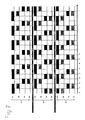
- An example of a possible timing of the by the device 1 after Fig. 1 realizable dosing or feed process is the in Fig. 2 shown diagram.
- a valve 10a is opened and a vacuum or negative pressure is established in the metering chamber 5a.
- the valve 12 a associated with the supply line 4 a is opened and the bulk material is sucked into the dosing chamber 5 a.
- the second dosing chamber 5b is already evacuated by opening the valve 10b, in order then to be filled at a time t 2 by opening the valve 12b from the supply line 4b.
- the powder suction in the first metering chamber 5a is completed by closing the valves 10a, 12a and by connecting this metering chamber 5a to the compressed gas line 8a and opening the discharge line 6a (via the valve 13a), the ejection phase of the bulk material from the metering chamber 5a initiated.
- This bulk material discharge is completed in the time t 3 , in which the powder intake into the second metering chamber 5 b is completed.
- the third metering chamber 5c is evacuated and the powder suction into this metering chamber 5c begins.
- timing diagram example preferably takes the evacuation of the metering chambers 5a, 5b, 5c twice as long as the powder intake. It could also be for the generation of the overpressure a longer time interval than for the bulk material ejection in question.
- the time intervals for opening and closing of the individual valves can now be set by pneumatic, electromagnetic, magnetic or hydraulic control in their size optionally with constant metering, whereby in a certain time different sized bulk quantities can be supplied in desired sub-doses in the further working process ,
- the switching times for one cycle are less than 1 s, and the discharge frequency of the metering chambers is about 1 Hz or more.
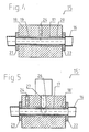
- Fig. 4 It may be any of the above-described, either one of the suction or compressed gas lines 7a, 7b, 7c or 8a, 8b, 8c or one of the supply or Austragungstechnischen 4a, 4b, 4c or 6a, 6b, 6c associated valves Fig. 1 act.
- the line 16 has a deformable in cross-section 17 in the form of an elastically flexible hose, the brain through a valve body 18 and a longitudinal opening 19 thereof.
- the longitudinal opening 19 forms a deformable in cross-section portion 17, the front side sealed by sealing devices 21, 22 pressure chamber 20.
- a opening into the pressure chamber 20 Querbobrung 24 in the valve body 18 forms the pressure port to the in Fig. 4 not shown pneumatic or hydraulic control.
- the dimensioning of the pressure chamber prevents rupture of the elastically flexible tube 17 and thus results in a shape stabilization.
- the portion 17 is compressed radially in its volume over a substantial part of its length and thereby the conduit 16 is closed.
- the wear of the tubes in the valves 15 is considerably reduced.
- the main advantage is the rapid response of these valves 15.
- valve 15 corresponds substantially to the valve 15 after Fig. 4 , wherein the constant parts are designated by like reference numerals.
- a further, radially opening into the pressure chamber 20 bore 26 is provided, in which a pneumatically, magnetically, electromagnetically or electro-pneumatically actuated crimping die 27 is slidably disposed as a closing member (a the valve 15 'closing position of the crimping plunger 27 is in Fig. 5 indicated by dashed lines).
- FIG Fig. 3 Another device 1 'for the pneumatic feeding of metered quantities of bulk material is shown schematically in FIG Fig. 3 shown. It is a sifter, by means of which the bulk material from a container 32 divided into different size classes is continued separately in metered quantities.
- the bulk material is conveyed pneumatically via a supply line 34a to the first metering chamber 35a, which is equipped with a filter 40a, by means of which the coarse bulk material retained and only bulk material is conveyed to a certain size via a supply line 34b to the second metering chamber 35b on.
- the third metering chamber 35c is provided with a filter 40c which merely transmits gas, by means of which even the finest bulk material is separated off, and which prevents the penetration of the bulk material into a suction line 37 connected to a vacuum or low-pressure source.
- the supply lines 34a, 34b, 34c and the suction line 37 are provided with valves 41, 42, 43, 44, via which the connection of the series-connected metering chambers 35a, 35b, 35c to the suction line 37 is turned on or off.
- Each metering chamber 35a, 35b, 35c is further connected via a respective valve 45a, 45b, 45c to a compressed gas line 38a, 38b, 38c and each equipped with a discharge line 36a, 36b, 36c for the bulk material.
- the discharge lines 36a, 36b, 36c are in turn provided with valves 46a, 46b, 46c.
- valves 41, 42, 43 and 44 By closing the valves 41, 42, 43 and 44, the suction is stopped, and the metering chambers 35a, 35b, 35c are connected via the valves 45a, 45b, 45c to the Druclcgas effet 38a, 38b, 38c, after which the ejection of the metered, metered Bulk material via the discharge lines 36a, 36b, 36c and the open valves 46a, 46b, 46c takes place.
- a corresponding control is present.
- the valves are preferably as in Fig. 4 or 5 shown formed.
- the desired frequency of filling and emptying of the metering chambers 35a, 35b, 35c can be set to selectively determine the amount of bulk material to be supplied.
- Both in the device 1 according to Fig. 1 as well as with those Fig. 3 can according to the invention instead of this frequency setting - or in addition to the same - the desired metering be determined by changing or setting the Dosierkanuner volume. Examples of metering bodies whose metering chambers are adjustable in volume are in FIG Fig. 6 to 10 shown.
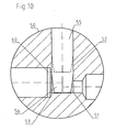
- FIG. 6 and 7 shows a metering body 50 with a metering chamber 51.
- the metering chamber 51 is formed by the periphery and a lower end face 53 of a central, circular in cross-section recess 52 in the metering body 50 (see also Fig. 10 ).
- the dosing chamber 51 is delimited by a longitudinally displaceable dosing ram 55 inserted in a tight sliding manner in the recess 52, or by its lower, cylindrical or conically tapering end piece 56.
- connection bores 57, 58, 59 which are arranged at right angles to the axis of the recess 52, open into the dosing chamber 51 (cf. Fig. 7 ).
- the metering chamber 51 is alternately connected to a suction or vacuum line on the one hand and a compressed gas line on the other hand, which are not shown here.
- the vacuum connection is in Fig. 7 with an arrow V, the Druclc Kunststoffan gleich indicated by an arrow D.
- the connection bore 58 the bulk material is sucked into the dosing chamber 51 in the direction of arrow S, via the connection hole 59 in the direction of arrow A. pushed out.
- a filter membrane 60 is arranged, which - as already mentioned - prevents the penetration of the bulk material into the gas lines.
- the lower end piece 56 of the metering ram 55 with its shape ensures that the filter membrane 60 arranged tangentially to the recess 52 can also be acted upon with the entire surface in the lower position of the metering ram 55 corresponding to the minimum dosing chamber volume.
- a metering body 50 ' which extends from the dosing 50 after 6 and 7 differs by the number and arrangement of the connection holes for the gas and bulk material lines.
- two connection bores are provided here in order to increase the membrane areas even further.
- a connection bore 59' which is coaxial to the recess 52 and points downwards from the dosing chamber 51, is provided for the bulk material discharge ( see. Fig. 9 ).
- the bulk material may be both powder, fine-grained substrates, but also liquids or liquid liteite powder mixtures.
- the concepts known to date of transporting powdered bulk materials by means of a transport gas are based on the principle of grafting or dense phase conveying and the transport of air or air. All processes require long stabilization times of the powder flow at the line outlet in the start and the stop phase of a transport cycle, in particular for long conveyor lines.
- the stabilization and stop time is a direct function of the average bulk material conveying speed in the transport piping system and the transport line length.
- the concept underlying the present invention is based on the transport of bulk material by means of momentum transfer, henceforth referred to as impulse delivery.
- impulse delivery In the case of a stop pulse, regardless of the transport line length, the bulk material transport stops immediately within a few seconds or, without a stabilization phase, almost at the same time as the starting pulse, a continuous and uniform powder flow forms at the transport line outlet.
- This is particularly advantageous when used in automated lines, in which, for example, products are continuously fed to a process and a transport stop of the bulk material in the period between two successive products to be processed is not desired.
- impulse delivery in automated coating lines eg in the automotive industry therefore allows significantly higher productivity, since among other things, the distance between two successive bodies is decisively reduced.
Landscapes
- Physics & Mathematics (AREA)
- Fluid Mechanics (AREA)
- General Physics & Mathematics (AREA)
- Electromagnetism (AREA)
- Weight Measurement For Supplying Or Discharging Of Specified Amounts Of Material (AREA)
Abstract
Claims (5)
- Procédé d'amenée de quantités dosées d'un produit en vrac à grain fin vers un autre processus opératoire, le produit en vrac étant transporté par des moyens pneumatiques depuis un conteneur (32) par le biais d'au moins deux chambres de dosage (35a, 35b, 35c ; 51) pouvant être alternativement remplies et vidées et étant emporté sous pression, le remplissage et le vidage des chambres de dosage étant effectués par une commande, le réglage de la fréquence souhaitée du remplissage et du vidage des chambres de dosage (35a, 35b, 35c ; 51) et/ou le réglage en dimension du volume des présentes chambres de dosage (35a, 35b, 35c ; 51) étant effectués afin de déterminer sélectivement les quantités de produit en vrac à amener, le remplissage de la chambre de dosage correspondante (35a, 35b, 35c ; 51) étant effectué à partir d'une conduite d'amenée de produit en vrac (34a, 34b, 34c ; 58 : 58') en raccordant la chambre de dosage à une conduite sous vide ou d'aspiration (37, 57; 57v), et la chambre de dosage étant raccordée à une conduite de gaz sous pression (38a, 38b, 38c ; 57; 57d) pour vider la chambre de dosage dans une conduite d'évacuation (36a, 36b, 36c ; 59, 59') ainsi que pour emporter le produit en vrac, le branchement et le débranchement du raccord d'aspiration ainsi que le branchement et le débranchement du raccord de gaz sous pression étant effectués par des clapets commandés par des moyens pneumatiques et/ou hydrauliques, caractérisé en ce que
le produit en vrac est amené vers l'autre processus opératoire par le biais de chambres de dosage (35a, 35b, 35c ; 51) montées en série, de préférence au nombre de trois, le produit en vrac réparti en différentes granulométries étant évacué des chambres de dosage individuelles (35a, 35b, 35c ; 51). - Procédé selon la revendication 1, caractérisé en ce que le produit en vrac est amené de façon continue vers l'autre processus opératoire par le biais de chambres de dosage (5a, 5b, 5c) montées en parallèle, de préférence au nombre de trois, les clapets fonctionnellement identiques étant actionnés dans un intervalle de temps l'un après l'autre pour remplir et vider les chambres de dosage individuelles (5a, 5b, 5c).
- Procédé selon la revendication 2, caractérisé en ce que l'amenée de produit en vrac à la chambre de dosage correspondante (5a, 5b, 5c) ainsi que l'évacuation du produit en vrac de la chambre de dosage correspondante (5a, 5b, 5c) sont effectuées à chaque fois par un clapet commandé (12a, 12b, 12c; 13a, 13b, 13c) permettant de maintenir ouvertes ou fermées la conduite d'amenée de produit en vrac (4a, 4b, 4c) et la conduite d'évacuation de produit en vrac (6a, 6b, 6c) des chambres de dosage correspondantes (5a, 5b, 5c).
- Procédé selon la revendication 3, caractérisé en ce que le branchement du raccord sous vide ou d'aspiration est effectué avant d'ouvrir la conduite d'amenée de produit en vrac (4a, 4b, 4c).
- Procédé selon la revendication 3 ou 4, caractérisé en ce que le branchement du raccord de gaz sous pression est effectué avant d'ouvrir la conduite d'évacuation (6a, 6b, 6c).
Applications Claiming Priority (3)
| Application Number | Priority Date | Filing Date | Title |
|---|---|---|---|
| CH17922001 | 2001-09-29 | ||
| CH179201 | 2001-09-29 | ||
| PCT/EP2002/010709 WO2003029762A1 (fr) | 2001-09-29 | 2002-09-25 | Procede et dispositif d'alimentation de quantites dosees d'un materiau en vrac a grains fins |
Publications (2)
| Publication Number | Publication Date |
|---|---|
| EP1432964A1 EP1432964A1 (fr) | 2004-06-30 |
| EP1432964B1 true EP1432964B1 (fr) | 2012-05-23 |
Family
ID=4566295
Family Applications (1)
| Application Number | Title | Priority Date | Filing Date |
|---|---|---|---|
| EP02774644A Expired - Lifetime EP1432964B1 (fr) | 2001-09-29 | 2002-09-25 | Procede et dispositif d'alimentation de quantites dosees d'un materiau en vrac a grains fins |
Country Status (2)
| Country | Link |
|---|---|
| EP (1) | EP1432964B1 (fr) |
| WO (1) | WO2003029762A1 (fr) |
Families Citing this family (8)
| Publication number | Priority date | Publication date | Assignee | Title |
|---|---|---|---|---|
| CH696811A5 (de) * | 2003-09-26 | 2007-12-14 | Michael Dvorak Dr Ing Dipl Phy | Verfahren zur Beschichtung einer Substratoberfläche unter Verwendung eines Plasmastrahles. |
| DE102004007967A1 (de) * | 2004-02-18 | 2005-09-08 | Dürr Systems GmbH | Pulverförderpumpe und zugehöriges Betriebsverfahren |
| DE202009005561U1 (de) * | 2009-04-16 | 2009-07-02 | Fass, Wolfgang, Dipl.-Ing. | Vorrichtung und Anordnung zum Befüllen von Verarbeitungsstationen |
| WO2010118881A2 (fr) * | 2009-04-17 | 2010-10-21 | Michael Dvorak | Procédé de revêtement par poudre ou de fabrication de matériaux composites, de préférence lors de la fabrication de plastiques ou du formage par pulvérisation de métaux |
| DE102010014552A1 (de) | 2010-03-22 | 2011-09-22 | Timo Brummer | Verfahren zur Plasmabeschichtung einer Substratoberfläche mit Beschichtungsflüssigkeit |
| KR20140061422A (ko) | 2011-07-25 | 2014-05-21 | 엑카르트 게엠베하 | 기판 코팅 방법 및 이러한 방법에서 첨가제 함유 분말 코팅 물질의 용도 |
| DE102011052119A1 (de) | 2011-07-25 | 2013-01-31 | Eckart Gmbh | Verfahren zur Substratbeschichtung und Verwendung additivversehener, pulverförmiger Beschichtungsmaterialien in derartigen Verfahren |
| ITMI20120635A1 (it) | 2012-04-17 | 2013-10-18 | Micro Macinazione S A | Apparecchiatura del tipo a mulino a getti per la micronizzazione di un materiale polveroso o in generale contenente particelle, con nuovo sistema di alimentazione e dosatura del materiale polveroso da micronizzare, e corrispondente procedimento di mi |
Family Cites Families (5)
| Publication number | Priority date | Publication date | Assignee | Title |
|---|---|---|---|---|
| US4211518A (en) * | 1974-12-07 | 1980-07-08 | Ruhrkohle Ag | Method and arrangement for hydraulic conveying of solids |
| US4462760A (en) * | 1978-04-14 | 1984-07-31 | Orbital Engine Company Proprietary Limited | Method and apparatus for metering liquids |
| GB2184709B (en) * | 1985-12-30 | 1989-10-18 | Cozzoli Machine | Apparatus for automatically filling a product into a receptacle |
| GB9104226D0 (en) * | 1991-02-28 | 1991-04-17 | Oxford Glycosystems Ltd | Liquid delivery system |
| DE19959473A1 (de) | 1999-12-10 | 2001-06-13 | Frederic Dietrich | Vorrichtung und Verfahren zum pneumatischen Fördern pulverförmiger Stoffe sowie Verwendung der Vorrichtung |
-
2002
- 2002-09-25 EP EP02774644A patent/EP1432964B1/fr not_active Expired - Lifetime
- 2002-09-25 WO PCT/EP2002/010709 patent/WO2003029762A1/fr not_active Ceased
Also Published As
| Publication number | Publication date |
|---|---|
| WO2003029762A1 (fr) | 2003-04-10 |
| EP1432964A1 (fr) | 2004-06-30 |
Similar Documents
| Publication | Publication Date | Title |
|---|---|---|
| EP2981365B1 (fr) | Pompe de transport de poudre en phase dense et procede de fonctionnement correspondant | |
| EP1427536B1 (fr) | Dispositif pour transporter de la poudre et procede pour le faire fonctionner | |
| DE102010039473B4 (de) | Pulverversorgungsvorrichtung für eine Pulverbeschichtungsanlage | |
| WO2002040160A1 (fr) | Dispositif et procede de separation d'echantillons a partir d'un liquide | |
| DE2212611B2 (de) | Vorrichtung zum fortlaufenden bilden von gutportionen und einbringen derselben in eine pneumatische foerderleitung | |
| DD241189A5 (de) | Verfahren zum injizieren viskoser fluessigkeit in brot oder konditoreiwaren | |
| EP1432964B1 (fr) | Procede et dispositif d'alimentation de quantites dosees d'un materiau en vrac a grains fins | |
| WO2016020096A1 (fr) | Dispositif de distribution de poudre et installation de distribution de poudre pour revêtir des objets de poudre | |
| AT516945B1 (de) | Vorrichtung zum Herstellen einer Mischung aus wenigstens einem Gas und wenigstens einer flüssigen Kunststoffkomponente | |
| EP3462140B1 (fr) | Procédé et dispositif de dosage pour une distribution de fluide dosée | |
| EP1424130B1 (fr) | Distributeur à canaux multiples avec calibrage automatique | |
| DE102017103487A1 (de) | Pulverdichtstrompumpe | |
| DE102007045330A1 (de) | Beschichtungspulver-Förderverfahren, Beschichtungspulver-Fördervorrichtung und elektrostatische Pulversprühbeschichtungsvorrichtung | |
| EP3921239B1 (fr) | Machine à sachet tubulaire à tuyau double avec dispositif de dosage et système de transfert | |
| DE3024568C2 (de) | Verfahren und Vorrichtung zum pneumatischen Fördern von Fördergut | |
| DE19536623C1 (de) | Verfahren und Vorrichtung zum Dosieren von Dickstoffen | |
| EP1578678B1 (fr) | Dispositif de distribution continue de sachets | |
| EP0763385B1 (fr) | Procédé de transport d'un matériaux pulvérulent au moyen d'un injecteur | |
| EP0692441B1 (fr) | Procédé et dispositf pour transport pneumatique de matériau en vrac | |
| DE69612111T2 (de) | Verfahren und vorrichtung zum abfüllen von schüttgut | |
| WO2009121567A2 (fr) | Dispositif et procédé de dosage exact de liquides | |
| DE69202084T2 (de) | Abgabesystem für Flüssigkeiten. | |
| EP3683185B1 (fr) | Dispositif et procédé de remplissage d'un récipient avec un produit de remplissage | |
| DE3317608C1 (de) | Trockendosierer | |
| DE2412142A1 (de) | Pneumatisches foerdersystem |
Legal Events
| Date | Code | Title | Description |
|---|---|---|---|
| PUAI | Public reference made under article 153(3) epc to a published international application that has entered the european phase |
Free format text: ORIGINAL CODE: 0009012 |
|
| 17P | Request for examination filed |
Effective date: 20040315 |
|
| AK | Designated contracting states |
Kind code of ref document: A1 Designated state(s): AT BE BG CH CY CZ DE DK EE ES FI FR GB GR IE IT LI LU MC NL PT SE SK TR |
|
| AX | Request for extension of the european patent |
Extension state: AL LT LV MK RO SI |
|
| 17Q | First examination report despatched |
Effective date: 20090821 |
|
| GRAP | Despatch of communication of intention to grant a patent |
Free format text: ORIGINAL CODE: EPIDOSNIGR1 |
|
| GRAS | Grant fee paid |
Free format text: ORIGINAL CODE: EPIDOSNIGR3 |
|
| GRAA | (expected) grant |
Free format text: ORIGINAL CODE: 0009210 |
|
| AK | Designated contracting states |
Kind code of ref document: B1 Designated state(s): AT BE BG CH CY CZ DE DK EE ES FI FR GB GR IE IT LI LU MC NL PT SE SK TR |
|
| REG | Reference to a national code |
Ref country code: GB Ref legal event code: FG4D Free format text: NOT ENGLISH |
|
| REG | Reference to a national code |
Ref country code: CH Ref legal event code: EP |
|
| REG | Reference to a national code |
Ref country code: AT Ref legal event code: REF Ref document number: 559283 Country of ref document: AT Kind code of ref document: T Effective date: 20120615 |
|
| REG | Reference to a national code |
Ref country code: IE Ref legal event code: FG4D Free format text: LANGUAGE OF EP DOCUMENT: GERMAN |
|
| REG | Reference to a national code |
Ref country code: DE Ref legal event code: R096 Ref document number: 50215485 Country of ref document: DE Effective date: 20120726 |
|
| REG | Reference to a national code |
Ref country code: CH Ref legal event code: NV Representative=s name: LUCHS & PARTNER PATENTANWAELTE |
|
| REG | Reference to a national code |
Ref country code: NL Ref legal event code: VDEP Effective date: 20120523 |
|
| REG | Reference to a national code |
Ref country code: CH Ref legal event code: PK |
|
| RAP2 | Party data changed (patent owner data changed or rights of a patent transferred) |
Owner name: DVORAK, MICHAEL |
|
| RIN2 | Information on inventor provided after grant (corrected) |
Inventor name: DVORAK, MICHAEL |
|
| PG25 | Lapsed in a contracting state [announced via postgrant information from national office to epo] |
Ref country code: CY Free format text: LAPSE BECAUSE OF FAILURE TO SUBMIT A TRANSLATION OF THE DESCRIPTION OR TO PAY THE FEE WITHIN THE PRESCRIBED TIME-LIMIT Effective date: 20120523 Ref country code: FI Free format text: LAPSE BECAUSE OF FAILURE TO SUBMIT A TRANSLATION OF THE DESCRIPTION OR TO PAY THE FEE WITHIN THE PRESCRIBED TIME-LIMIT Effective date: 20120523 Ref country code: SE Free format text: LAPSE BECAUSE OF FAILURE TO SUBMIT A TRANSLATION OF THE DESCRIPTION OR TO PAY THE FEE WITHIN THE PRESCRIBED TIME-LIMIT Effective date: 20120523 |
|
| PG25 | Lapsed in a contracting state [announced via postgrant information from national office to epo] |
Ref country code: PT Free format text: LAPSE BECAUSE OF FAILURE TO SUBMIT A TRANSLATION OF THE DESCRIPTION OR TO PAY THE FEE WITHIN THE PRESCRIBED TIME-LIMIT Effective date: 20120924 Ref country code: GR Free format text: LAPSE BECAUSE OF FAILURE TO SUBMIT A TRANSLATION OF THE DESCRIPTION OR TO PAY THE FEE WITHIN THE PRESCRIBED TIME-LIMIT Effective date: 20120824 |
|
| PG25 | Lapsed in a contracting state [announced via postgrant information from national office to epo] |
Ref country code: SK Free format text: LAPSE BECAUSE OF FAILURE TO SUBMIT A TRANSLATION OF THE DESCRIPTION OR TO PAY THE FEE WITHIN THE PRESCRIBED TIME-LIMIT Effective date: 20120523 Ref country code: CZ Free format text: LAPSE BECAUSE OF FAILURE TO SUBMIT A TRANSLATION OF THE DESCRIPTION OR TO PAY THE FEE WITHIN THE PRESCRIBED TIME-LIMIT Effective date: 20120523 Ref country code: DK Free format text: LAPSE BECAUSE OF FAILURE TO SUBMIT A TRANSLATION OF THE DESCRIPTION OR TO PAY THE FEE WITHIN THE PRESCRIBED TIME-LIMIT Effective date: 20120523 Ref country code: EE Free format text: LAPSE BECAUSE OF FAILURE TO SUBMIT A TRANSLATION OF THE DESCRIPTION OR TO PAY THE FEE WITHIN THE PRESCRIBED TIME-LIMIT Effective date: 20120523 Ref country code: NL Free format text: LAPSE BECAUSE OF FAILURE TO SUBMIT A TRANSLATION OF THE DESCRIPTION OR TO PAY THE FEE WITHIN THE PRESCRIBED TIME-LIMIT Effective date: 20120523 |
|
| PLBE | No opposition filed within time limit |
Free format text: ORIGINAL CODE: 0009261 |
|
| STAA | Information on the status of an ep patent application or granted ep patent |
Free format text: STATUS: NO OPPOSITION FILED WITHIN TIME LIMIT |
|
| BERE | Be: lapsed |
Owner name: DVORAK, MICHAEL Effective date: 20120930 Owner name: BIRCHLER, MARKUS Effective date: 20120930 |
|
| PG25 | Lapsed in a contracting state [announced via postgrant information from national office to epo] |
Ref country code: ES Free format text: LAPSE BECAUSE OF FAILURE TO SUBMIT A TRANSLATION OF THE DESCRIPTION OR TO PAY THE FEE WITHIN THE PRESCRIBED TIME-LIMIT Effective date: 20120903 Ref country code: MC Free format text: LAPSE BECAUSE OF NON-PAYMENT OF DUE FEES Effective date: 20120930 |
|
| 26N | No opposition filed |
Effective date: 20130226 |
|
| REG | Reference to a national code |
Ref country code: IE Ref legal event code: MM4A |
|
| REG | Reference to a national code |
Ref country code: DE Ref legal event code: R097 Ref document number: 50215485 Country of ref document: DE Effective date: 20130226 |
|
| PG25 | Lapsed in a contracting state [announced via postgrant information from national office to epo] |
Ref country code: IE Free format text: LAPSE BECAUSE OF NON-PAYMENT OF DUE FEES Effective date: 20120925 Ref country code: BG Free format text: LAPSE BECAUSE OF FAILURE TO SUBMIT A TRANSLATION OF THE DESCRIPTION OR TO PAY THE FEE WITHIN THE PRESCRIBED TIME-LIMIT Effective date: 20120823 Ref country code: BE Free format text: LAPSE BECAUSE OF NON-PAYMENT OF DUE FEES Effective date: 20120930 |
|
| REG | Reference to a national code |
Ref country code: AT Ref legal event code: MM01 Ref document number: 559283 Country of ref document: AT Kind code of ref document: T Effective date: 20120925 |
|
| PG25 | Lapsed in a contracting state [announced via postgrant information from national office to epo] |
Ref country code: AT Free format text: LAPSE BECAUSE OF NON-PAYMENT OF DUE FEES Effective date: 20120925 |
|
| PG25 | Lapsed in a contracting state [announced via postgrant information from national office to epo] |
Ref country code: TR Free format text: LAPSE BECAUSE OF FAILURE TO SUBMIT A TRANSLATION OF THE DESCRIPTION OR TO PAY THE FEE WITHIN THE PRESCRIBED TIME-LIMIT Effective date: 20120523 |
|
| PG25 | Lapsed in a contracting state [announced via postgrant information from national office to epo] |
Ref country code: LU Free format text: LAPSE BECAUSE OF NON-PAYMENT OF DUE FEES Effective date: 20120925 |
|
| REG | Reference to a national code |
Ref country code: FR Ref legal event code: PLFP Year of fee payment: 15 |
|
| PGFP | Annual fee paid to national office [announced via postgrant information from national office to epo] |
Ref country code: GB Payment date: 20160921 Year of fee payment: 15 |
|
| PGFP | Annual fee paid to national office [announced via postgrant information from national office to epo] |
Ref country code: FR Payment date: 20160922 Year of fee payment: 15 |
|
| PGFP | Annual fee paid to national office [announced via postgrant information from national office to epo] |
Ref country code: IT Payment date: 20160922 Year of fee payment: 15 |
|
| GBPC | Gb: european patent ceased through non-payment of renewal fee |
Effective date: 20170925 |
|
| REG | Reference to a national code |
Ref country code: FR Ref legal event code: ST Effective date: 20180531 |
|
| PG25 | Lapsed in a contracting state [announced via postgrant information from national office to epo] |
Ref country code: GB Free format text: LAPSE BECAUSE OF NON-PAYMENT OF DUE FEES Effective date: 20170925 |
|
| PG25 | Lapsed in a contracting state [announced via postgrant information from national office to epo] |
Ref country code: FR Free format text: LAPSE BECAUSE OF NON-PAYMENT OF DUE FEES Effective date: 20171002 Ref country code: IT Free format text: LAPSE BECAUSE OF NON-PAYMENT OF DUE FEES Effective date: 20170925 |
|
| PGFP | Annual fee paid to national office [announced via postgrant information from national office to epo] |
Ref country code: DE Payment date: 20190923 Year of fee payment: 18 |
|
| PGFP | Annual fee paid to national office [announced via postgrant information from national office to epo] |
Ref country code: CH Payment date: 20191001 Year of fee payment: 18 |
|
| REG | Reference to a national code |
Ref country code: DE Ref legal event code: R119 Ref document number: 50215485 Country of ref document: DE |
|
| REG | Reference to a national code |
Ref country code: CH Ref legal event code: PL |
|
| PG25 | Lapsed in a contracting state [announced via postgrant information from national office to epo] |
Ref country code: DE Free format text: LAPSE BECAUSE OF NON-PAYMENT OF DUE FEES Effective date: 20210401 |
|
| PG25 | Lapsed in a contracting state [announced via postgrant information from national office to epo] |
Ref country code: CH Free format text: LAPSE BECAUSE OF NON-PAYMENT OF DUE FEES Effective date: 20200930 Ref country code: LI Free format text: LAPSE BECAUSE OF NON-PAYMENT OF DUE FEES Effective date: 20200930 |