EP1433428A1 - Ultraschallbehandlungsgerät - Google Patents
Ultraschallbehandlungsgerät Download PDFInfo
- Publication number
- EP1433428A1 EP1433428A1 EP03766699A EP03766699A EP1433428A1 EP 1433428 A1 EP1433428 A1 EP 1433428A1 EP 03766699 A EP03766699 A EP 03766699A EP 03766699 A EP03766699 A EP 03766699A EP 1433428 A1 EP1433428 A1 EP 1433428A1
- Authority
- EP
- European Patent Office
- Prior art keywords
- probe
- grasping
- treatment apparatus
- living tissue
- jaw
- Prior art date
- Legal status (The legal status is an assumption and is not a legal conclusion. Google has not performed a legal analysis and makes no representation as to the accuracy of the status listed.)
- Granted
Links
Images







Classifications
-
- A—HUMAN NECESSITIES
- A61—MEDICAL OR VETERINARY SCIENCE; HYGIENE
- A61N—ELECTROTHERAPY; MAGNETOTHERAPY; RADIATION THERAPY; ULTRASOUND THERAPY
- A61N7/00—Ultrasound therapy
- A61N7/02—Localised ultrasound hyperthermia
-
- A—HUMAN NECESSITIES
- A61—MEDICAL OR VETERINARY SCIENCE; HYGIENE
- A61B—DIAGNOSIS; SURGERY; IDENTIFICATION
- A61B18/00—Surgical instruments, devices or methods for transferring non-mechanical forms of energy to or from the body
- A61B18/04—Surgical instruments, devices or methods for transferring non-mechanical forms of energy to or from the body by heating
- A61B18/12—Surgical instruments, devices or methods for transferring non-mechanical forms of energy to or from the body by heating by passing a current through the tissue to be heated, e.g. high-frequency current
- A61B18/14—Probes or electrodes therefor
- A61B18/1442—Probes having pivoting end effectors, e.g. forceps
- A61B18/1445—Probes having pivoting end effectors, e.g. forceps at the distal end of a shaft, e.g. forceps or scissors at the end of a rigid rod
-
- A—HUMAN NECESSITIES
- A61—MEDICAL OR VETERINARY SCIENCE; HYGIENE
- A61B—DIAGNOSIS; SURGERY; IDENTIFICATION
- A61B17/00—Surgical instruments, devices or methods
- A61B17/28—Surgical forceps
- A61B17/2812—Surgical forceps with a single pivotal connection
- A61B17/282—Jaws
- A61B2017/2825—Inserts of different material in jaws
-
- A—HUMAN NECESSITIES
- A61—MEDICAL OR VETERINARY SCIENCE; HYGIENE
- A61B—DIAGNOSIS; SURGERY; IDENTIFICATION
- A61B17/00—Surgical instruments, devices or methods
- A61B17/28—Surgical forceps
- A61B17/2812—Surgical forceps with a single pivotal connection
- A61B17/282—Jaws
- A61B2017/2829—Jaws with a removable cover
-
- A—HUMAN NECESSITIES
- A61—MEDICAL OR VETERINARY SCIENCE; HYGIENE
- A61B—DIAGNOSIS; SURGERY; IDENTIFICATION
- A61B17/00—Surgical instruments, devices or methods
- A61B17/32—Surgical cutting instruments
- A61B17/320068—Surgical cutting instruments using mechanical vibrations, e.g. ultrasonic
- A61B17/320092—Surgical cutting instruments using mechanical vibrations, e.g. ultrasonic with additional movable means for clamping or cutting tissue, e.g. with a pivoting jaw
- A61B2017/320093—Surgical cutting instruments using mechanical vibrations, e.g. ultrasonic with additional movable means for clamping or cutting tissue, e.g. with a pivoting jaw additional movable means performing cutting operation
-
- A—HUMAN NECESSITIES
- A61—MEDICAL OR VETERINARY SCIENCE; HYGIENE
- A61B—DIAGNOSIS; SURGERY; IDENTIFICATION
- A61B17/00—Surgical instruments, devices or methods
- A61B17/32—Surgical cutting instruments
- A61B17/320068—Surgical cutting instruments using mechanical vibrations, e.g. ultrasonic
- A61B17/320092—Surgical cutting instruments using mechanical vibrations, e.g. ultrasonic with additional movable means for clamping or cutting tissue, e.g. with a pivoting jaw
- A61B2017/320095—Surgical cutting instruments using mechanical vibrations, e.g. ultrasonic with additional movable means for clamping or cutting tissue, e.g. with a pivoting jaw with sealing or cauterizing means
-
- A—HUMAN NECESSITIES
- A61—MEDICAL OR VETERINARY SCIENCE; HYGIENE
- A61B—DIAGNOSIS; SURGERY; IDENTIFICATION
- A61B90/00—Instruments, implements or accessories specially adapted for surgery or diagnosis and not covered by any of the groups A61B1/00 - A61B50/00, e.g. for luxation treatment or for protecting wound edges
- A61B90/08—Accessories or related features not otherwise provided for
- A61B2090/0813—Accessories designed for easy sterilising, i.e. re-usable
Definitions
- the present invention relates to a technology for performing medical procedures such as cutting, removing, and coagulation of living tissues using ultrasonic vibration.
- the ultrasonic treatment apparatus includes an elongated insertion sheath that is inserted into a hollow portion of a body, a probe that is projected from a distal end of the insertion sheath, and a tip action unit that is rotatably arranged at the distal end of the insertion sheath and that moves in an opening/closing manner with respect to the probe.
- An operating section is provided near the proximal end of the ultrasonic treatment apparatus to operate the tip action unit rotationally.
- operation of the operating section moves the tip action unit closer to the probe to grasp the living tissue between the probe and the tip action unit.
- the ultrasonic vibration to the probe, it is possible to perform the medical procedures such as coagulation and cutting of the living tissue between the probe and the tip action unit.
- the tip action unit of the ultrasonic treatment apparatus includes a jaw that moves in an opening/closing manner in response to the operation of the operating section, and a grasping member pivotably supported by the jaw.
- This configuration is effective to apply a uniform grasping force over the entire length of the grasping member when the tip action unit is closed to grasp the living tissue between the probe and the tip action unit.
- the grasping member is rotatably attached to the jaw via a pin that is arranged perpendicular to the longitudinal direction of the probe. In this case, when grasping the living tissue, the grasping member is forced to tilt to follow the deflection of the probe and thus applying a uniform grasping force over the entire length of the grasping member.
- the grasping member includes two elements: a first element and a second element.
- the first element is molded of a resin that exhibits a low friction coefficient against the probe and has excellent heat resistance and abrasion resistance, such as polytetrafluoroethylene (PTFE). It is arranged in a direction facing the probe.
- the second element is molded of a metal in a frame shape, which has a relatively high rigidity and tenacity, and is configured to cover the outer surface of the first element and contains a portion for pivotably supporting the jaw.
- the present invention is to solve the above problems and accordingly provides an ultrasonic treatment apparatus that can achieve an improved cleaning mechanism for cleaning in a shorter time and an easy recyclability.
- An ultrasonic treatment apparatus for performing a medical treatment to a living tissue includes a probe to which ultrasonic vibration is applied, and a tip action unit that moves in an opening/closing manner with respect to the probe on operation of an operating section.
- the tip action unit includes a jaw that moves in an opening/closing manner in response to the operation of the operating section, and a grasping member pivotably supported by the jaw for grasping the living tissue with the probe.
- the grasping member includes a first element molded of a heat resistant resin, and a second element located inside the first element as a reinforcement in such a manner that the first element covers the outer surface of the second element entirely.
- the ultrasonic vibration is applied to the probe while grasping the living tissue between the probe and the tip action unit.
- An ultrasonic treatment apparatus for performing a medical treatment to a living tissue includes a probe to which ultrasonic vibration is applied, and a tip action unit that moves in an opening/closing manner with respect to the probe on operation of an operating section.
- the tip action unit includes a jaw that moves in an opening/closing manner in response to the operation of the operating section, and a grasping member pivotably supported by the jaw for grasping the living tissue with the probe.
- the grasping member includes at least a first element molded of a heat resistant resin, and a second element located inside the first element as a reinforcement in such a manner that the first element covers the outer surface of the second element with at least a portion of the second element exposed.
- the ultrasonic vibration is applied to the probe while grasping the living tissue between the probe and the tip action unit.
- An ultrasonic treatment apparatus has a mechanism that a filling member is filled between the first element and the second element to tightly contact the first element with the second element.
- An ultrasonic treatment apparatus has a mechanism that the second element is a metallic material extended along an extending direction of the probe.
- An ultrasonic treatment apparatus has a mechanism that the second element includes a portion pivotably supported by the jaw.
- An ultrasonic:treatment apparatus for performing a medical treatment to a living tissue includes a probe to which ultrasonic vibration is applied, and a tip action unit that moves in an opening/closing manner with respect to the probe on operation of an operating section.
- the tip action unit includes a jaw that moves in an opening/closing manner in response to the operation of the operating section, and a grasping member pivotably supported by the jaw for grasping the living tissue with the probe.
- the grasping member is molded of a heat resistant resin. The ultrasonic vibration is applied to the probe while grasping the living tissue between the probe and the tip action unit.
- Fig. 1 is an external view of an ultrasonic treatment apparatus according to a first embodiment of the present invention
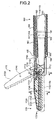
- Fig. 2 is a cross-sectional view of a distal end of the ultrasonic treatment apparatus illustrated in Fig. 1
- Fig. 3 is a cross-sectional view cut along III-III line in Fig. 2
- Fig. 4 is a cross-sectional view cut along IV-IV line in Fig. 3
- Fig. 5 is a cross-sectional side view of the ultrasonic treatment apparatus illustrated in Fig. 1
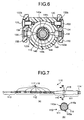
- Fig. 6 is a cross-sectional view cut along VI-VI line in Fig. 5
- Fig. 7(a) is an external side view of a probe of the ultrasonic treatment apparatus illustrated in Fig. 1
- Fig. 7(a) is an external side view of a probe of the ultrasonic treatment apparatus illustrated in Fig. 1
- Fig. 7(a) is an external side view of a probe of the ultrasonic treatment apparatus illustrated in Fig. 1
- FIG. 7(b) is a cross-sectional view cut along VII-VII line in Fig. 7(a);
- Fig. 8(a) is a perspective view of a tip action unit;
- Fig. 8(b) is an exploded perspective view of the tip action unit;
- Fig. 9(a) to Fig. 9(c) are schematic diagrams for illustrating process steps of manufacturing a grasping member;
- Fig. 10 is a plan view of an ultrasonic treatment apparatus according to a second embodiment of the present invention;
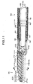
- Fig. 11 is a cross-sectional side view of the ultrasonic treatment apparatus illustrated in Fig. 10;
- Fig. 12 is a cross-sectional view cut along XII-XII line in Fig. 11;
- FIG. 13(a) is a perspective view of the tip action unit
- Fig. 13(b) is an exploded perspective view of the tip action unit
- Fig. 14(a) to Fig. 14(c) are schematic diagrams for illustrating process steps of manufacturing the grasping member.
- Fig. 1 to Fig. 9 are schematic diagrams for illustrating an ultrasonic treatment apparatus according to a first embodiment of the present invention.
- the ultrasonic treatment apparatus is employed for performing medical procedures such as cutting, removing, and coagulation of living tissues using ultrasonic wave.
- the ultrasonic treatment apparatus includes a vibrator 10 and a treatment unit 100 separable from each other as illustrated in Fig. 1.
- the vibrator 10 includes, inside a vibrator cover 11, an ultrasonic vibrator 12 as a vibrating source.
- the ultrasonic vibrator 12 such as a piezoelectric element converts a given electric signal into a mechanical vibration.
- the ultrasonic vibrator 12 may vibrate at a frequency of 20 kilohertz or higher.
- the first embodiment applies one that vibrates at 47 kilohertz when the electric signal is given.
- a cable 13 is connected to the rear end of the vibrator 10 (on the right side end of the vibrator 10 in Fig. 1).
- a horn 14 and an attachment 15 are provided at the front end of the vibrator 10 (on the left side end of the vibrator 10 in Fig. 5).
- the cable 13 is employed to lead an electric signal output from a power source (not shown) to the ultrasonic vibrator 12 to vibrate it.
- the horn 14 is attached to the ultrasonic vibrator 12 to amplify and output the vibration when the ultrasonic vibrator 12 vibrates.
- a female threaded portion 16 is formed in the distal end of the horn 14.
- the attachment 15 is employed to detachably connect the vibrator 10 to the treatment unit 100 later described, and includes an attachment ring 17 around the perimeter of the distal end.
- the attachment ring 17 is a metallic annular member, which is partly cut off for being elastically deformable in the radial direction though it is not illustrated definitely in the drawing.
- the treatment unit 100 includes a probe 110, and a unit body 120 configured to attach the probe 110 exteriorly.
- the probe 110 is an elongated member having an input portion 111, a waveguide portion 112 and a treatment portion 113.
- a male threaded portion 114 is formed around the proximal end of the input portion 111.
- the probe 110 is: composed of a bio-compatible metallic material such as a titanium alloy.
- the length of the probe 110 is formed as a length corresponding to an integral multiple of a half wavelength of the vibration caused by the ultrasonic vibrator 12.
- the ultrasonic vibrator 12 vibrates, the vibration amplified through the horn 14 is transmitted to the probe 110, which resonates with the vibrator to ultrasonic-vibrate the treatment portion 113.
- the input portion 111 of the probe 110 is formed in a cylindrical shape with a relatively large diameter having a flange 115 at the distal end. thereof as illustrated in Fig. 7(a).
- the flange 115 is a large diameter portion formed around the perimeter at a position that corresponds to a segment of vibration closest to the proximal end when the ultrasonic vibrator 12 vibrates.
- the flange 115 has flat portions 115a formed on a plurality of positions in the outer circumferential surface thereof as illustrated in Fig. 7(b).
- the waveguide portion 112 of the probe 110 is an elongated columnar member formed to have a smaller diameter than that of the input portion 111 as illustrated in Fig. 7(a), and is connected to the distal end of the input portion 111 via a tapered portion 116.
- the waveguide portion 112 has small diameter portions 117 formed on a plurality of positions that correspond to segments of vibration when the ultrasonic vibrator 12 vibrates.
- rubber rings 118 are mounted around a plurality of positions that correspond to segments of vibration.
- the small diameter portions 117 have a reduced cross section so as to provide the treatment portion 113 with a desired amplitude when the ultrasonic vibrator 12 vibrates.
- the rubber rings 118 are interposed between the waveguide portion 112 and an insert portion 160 later described to prevent the waveguide portion 112 and the insert portion 160 from interfering with each other.
- the treatment portion 113 of the probe 110 is a portion that directly contacts living tissues such as blood vessels, and has a uniform outer diameter and is formed in a linearly extending cylindrical shape with a small diameter.
- the unit body 120 is formed in a cylindrical shape having openings at both ends.
- the unit body 120 includes an external connection member 121 and an internal connection member 122 arranged on the inner circumference in the opening at the proximal end, and also includes an operating section 130 arranged on the outer circumference in the middle portion.
- the external connection member 121 and the internal connection member 122 are attached to the unit body 120 to form an annular groove therebetween for accommodating the attachment 15 and the attachment ring 17 of the vibrator 10 therein.
- the external connection member 121 has a projection 121 a on the inner circumferential surface at the proximal end thereof.
- the projection 121 a has such an inner diameter that restricts the passage of the attachment ring 17 when it is in a normal state and allows the passage of the attachment ring 17 when it has a reduced diameter due to elastic deformation.
- the attachment 15 and the attachment ring 17 of the vibrator 10 are squeezed in between the external connection member 121 and the internal connection member 122, the attachment ring 17 is appropriately elastically deformed and engaged with the projection 121a. As a result, the vibrator 10 can be detachably attached to the proximal end of the unit body 120.
- the operating section 130 is a portion to be operated by an operator for treatment of living tissues, and includes a stationary handle 131 and a movable handle 132.
- the stationary handle 131 extends from the unit body 120 outward in the radial direction and has a stationary finger-engaging portion 131 a at the extended end thereof.
- the stationary handle 131 is formed integrally with the unit body 120.
- the movable handle 132 has a movable finger-engaging portion 132a at the proximal end thereof, and has pin insertion holes 132b at the bifurcated distal ends thereof.
- the movable handle 132 is rotatably attached to the unit body 120 using fulcrum pins 133 mounted to the unit body 120 through the pin insertion holes 132b. As illustrated in Fig.
- bushes 134 composed of a resin having a low friction coefficient such as PTFE are disposed around the perimeters of the fulcrum pins 133 for the purpose of providing an improved sliding ability relative to the movable handle 132.
- the movable handle 132 includes action pins 135 arranged at locations closer to the proximal ends than the fulcrum pins 133. These action pins 135 have individual distal ends that are protruded inside the unit body 120 through action grooves 120a formed in the unit body 120.
- the movable handle 132 can be rotated about the fulcrum pins 133.
- the action pins 135 move in the action grooves 120a of the unit body 120 along the axial direction as the movable handle 132 rotates.
- the unit body 120 includes a drive mechanism 140 therein.
- the drive mechanism 140 is located on the perimeter of the probe 110 when the vibrator 10 is mounted on the unit body 120 while the probe 110 is attached to the horn 14.
- the drive mechanism 140 includes a connection member 141, a pipe fixing member 142, a driving force transmission member 143, a slide support member 144, and a contact member 145.
- connection member 141 is attached to the opening at the distal end of the unit body 120 via a fixing ring 146 so that it can rotate inside the unit body 120 about the axis thereof.
- the connection member 141 is formed in a cylindrical shape having an outer diameter that increases stepwise toward the proximal end.
- the connection member 141 has an elliptical hole 141 a extending along the axial direction at a portion located closest to the proximal end.
- a rotary knob 147 for rotating operation is attached to the connection member 141 on the perimeter at a portion protruded from the distal end of the unit body 120.
- the pipe fixing member 142 is formed in a cylindrical shape and attached to the inner circumferential surface in the distal end of the connection member 141 via a fixing pin 142a to rotate together with the connection member 141.
- the driving force transmission member 143 is located on the inner circumferential surface in the proximal end of the connection member 141, and can slidably move along the axial direction of the connection member 141.
- the driving force transmission member 143 includes an engaging pin 143a on the outer circumferential surface thereof, and can rotate integrally with the connection member 141 when the engaging pin 143a is engaged in the elliptical hole 141a of the connection member 141.
- a packing 143b is mounted on the outer circumference. This packing 143b serves to prevent an aeroperitoneum gas from externally leaking during a surgical operation under laparoscope.
- the pipe fixing member 142 and the driving force transmission member 143 are provided with interference preventive rings 142b and 143c, respectively on the inner circumferential surfaces.
- the interference preventive rings 142b and 143c are mounted on the pipe fixing member 142 and the driving force transmission member 143 for the purpose of preventing the probe 110 from contacting directly with the pipe fixing member 142 or the driving force transmission member 143.
- a resin having a low friction coefficient such as PTFE is molded to form rings, which are applied as the interference preventive rings 142b and 143c.
- the slide support member 144 is formed in a cylindrical shape having a flange-like support 144a at the proximal end thereof. It is coupled to the proximal end of the driving force transmission member 143 via coupling pins 144b. As illustrated in Fig. 6, the proximal end of the slide support member 144 is shaped to have a deformed hole that has flat portions 144c formed at two opposite locations on the inner surface. A slider 148 and a coil spring 149 are arranged on the perimeter of the slide support member 144.
- the slider 148 is formed in an annular shape that can fit around the perimeter of the slide support member 144, and can slide along the axial direction of the slide support member 144.
- the slider 148 has an engaging groove 148a formed in the perimeter thereof. The distal end of the action pin 135 protruded inside the unit body 120 via the action groove 120a engages in the engaging groove 148a.
- the coil spring 149 is a compressible spring interposed between the surface on the proximal end of the driving force transmission member 143 and the surface on the distal end of the slider 148. In a normal state, the coil spring 149 moves the slider 148 to a location closest to the proximal end to hold the surface on the proximal end of the slider 148 in contact with the support 144a of the slide support member 144. When the slider 148 moves from this state toward the distal end of the slide support member 144 in the axial direction, a certain spring force acts to press the driving force transmission member 143 toward the distal end.
- the contact member 145 is an electrically conductive cylindrical member with a distal end having an external form corresponding to the flat portion 144c of the slide support member 144.
- the contact member 145 is arranged in such a manner that the distal end fits in the proximal end of the slide support member 144.
- the contact member 145 is arranged at a location so as to cover the perimeter of the input portion 111 of the probe 110, and has an inner circumferential surface shaped to fit around the flange 115 of the probe 110.
- the contact member 145 is provided with elastic pieces 145a on the proximal end thereof.
- the elastic pieces 145a are configured by forming slits (not shown) in the proximal end of the contact member 145 along the axial direction, each having a protrusion 145b at an individual free end.
- the protrusion 145b is configured to have an outer diameter larger than the inner diameter of the internal connection member 122.
- connection rubber 150 molded of an electrically conductive rubber is attached to the distal end of the contact member 145.
- the connection rubber 150 is employed to ensure an electrical connection with the probe 110 and is press-contacted with the outer circumferential surface of the probe 110 in the vicinity of the position corresponding to the segment of vibration in the probe 110.
- a protrusion 150a is formed outside the connection rubber 150 to ensure air-tightness between the connection rubber 150 and the inner circumferential surface of the slide support member 144.
- the protrusion 150a of the connection rubber 150 serves to prevent an aeroperitoneum gas from externally leaking during a surgical operation under laparoscope.
- the reference numeral 151 in Fig. 5 denotes a high-frequency connection pin provided in the unit body 120.
- the high-frequency connection pin 151 is connected to an active cord for supplying a high-frequency current from a high-frequency cautery power source (not shown) and is attached to the proximal end of the unit body 120 so as to be electrically connected to the internal connection member 122.
- An insulating cover 152 is attached to the proximal end of the high-frequency connection pin 151 to ensure the electrical security while the active cord is attached thereto.
- the connection member 141, the pipe fixing member 142, the driving force transmission member 143 and the slide support member 144 follow to rotate relative to the unit body 120.
- the slide support member 144 rotates the contact member 145 and the probe 110 in the same direction.
- the protrusion 145b of the contact member 145 is always in contact with the internal connection member 122 to maintain electric connection therebetween by the elasticity of the elastic pieces 145a.
- the probe 110 is always electrically connected with the high-frequency connection pin 151 via the internal connection member 122, the contact member 145, and the connection rubber 150.
- the treatment portion 113 is employed, for example, to flow the high-frequency current to treat a living tissue.
- the treatment unit 100 further includes an insertion sheath 160 at the distal end of the unit body 120.
- the insertion sheath 160 is an elongated small-diameter portion to be inserted into a hollow portion of the body in a patient during a surgical operation under laparoscope, and has a double structure that includes an outer pipe 161 and an inner pipe 162.
- the outer pipe 161 extends from the distal end to the inside of the rotary knob 147 and the proximal end thereof is fixed on the inner circumferential surface of the pipe fixing member 142.
- the outer circumferential surface of the outer pipe 161 is covered by an insulating tube 163.
- the inner pipe 162 forms a channel inside for passing the waveguide portion 112 and the treatment portion 113 of the probe 110 through.
- the rubber rings 118 are interposed between the inner pipe 162 and the waveguide portion 112.
- a tip cover 164 is attached to the distal end of the outer pipe 161 of the insertion sheath 160 as illustrated in Fig. 2.
- the tip cover 164 is employed to pass the probe 110 through via a retaining member 165, and is arranged at a location that externally exposes the treatment portion 113 of the probe 110 from the distal end of the cover when the vibrator 10 is mounted on the unit body 120 while the horn 14 is attached to the probe 110.
- a tip action unit 170 is provided on the tip cover 164.
- the tip action unit 170 is employed to grasp a living tissue between the section 170 and the treatment portion 113 of the probe 110, and includes a jaw 1710 and a grasping member 1720.
- the jaw 1710 is molded of a metal having bio-compatibility and desired rigidity and tenacity, such as stainless steel. It has bifurcated tip supports 1711 as illustrated in Fig. 8(a) and Fig. 8(b). As illustrated in Fig. 4, the jaw 1710 has a proximal end attached to the tip cover 164 using two rotation support pins 1712 that are arranged laterally on the same axis. The jaw 1710 can rotate about the axis that is orthogonal to the extending direction of the insertion sheath 160.
- a link pin 1713 is attached to the jaw 1710.
- the link pin 1713 is arranged at a location decentered to avoid the rotation support pins 1712 along the axial direction of the rotation support pins 1712 and is connected to a drive link 1730 at the distal end.
- the drive link 1730 extends within the insertion sheath 160 along the channel provided between the outer pipe 161 and the inner pipe 162.
- the proximal end of the drive link is coupled to the driving force transmission member 143 via a driving force transmission pin 1731 as illustrated in Fig. 5.
- the grasping member 1720 is a portion that directly contacts with living tissues such as blood vessels together with the treatment portion 113 of the probe 110.
- the grasping member 1720 includes a first element 1721 and a second element 1722.
- the first element 1721 has a pinch 1721 a that opposes to the treatment portion 113 of the probe 110, and a tip bearing 1721 b that is mounted in between the tip supports 1711 of the jaw 1710.
- the first element 1721 is integrally molded of a resin, which exhibits a low friction coefficient against the probe 110 and is excellent in heat resistance (about 170°C) and abrasion resistance, such as PTFE and perfluoroalkoxylalkane (PFA). As illustrated in Fig.
- the pinch 1721 a has a trench with a curved central portion corresponding to the treatment portion 113 of the probe 110, and serrated parts on portions at both sides of the trench.
- the second element 1722 is molded of a metal having higher rigidity and tenacity compared to PTFE and PFA, such as a stainless steel.
- the second element 1722 is buried as reinforcement in the first element 1721.
- the second element 1722 extends almost along the entire length of the first element 1721 and has a portion corresponding to the tip bearing 1721 b of the first element 1721.
- the outer surface of the second element 1722 is covered entirely by the first element 1721 and has no portion which is externally exposed.
- the grasping member 1720 is supported pivotably movable about the axis that is orthogonal to the extending direction of the insertion sheath 160.
- the tip bearing 1721b is supported in between the tip supports 1711 of the jaw 1710, and a support pin 1740 is passed through the tip supports 1711 and tip bearing 1721b and the second element 1722.
- the grasping member 1720 can be produced easily by insert molding the first element 1721 around the second element 1722 if PFA is applied as the first element 1721.
- a method illustrated in Fig. 9(a) to Fig. 9(c) may be employed.
- the second element 1722 molded in a desired shape and a base 1721A and a lid 1721 B both molded of PTFE are prepared.
- the base 1721A is formed in a rectangular parallelepiped shape sufficient for molding the lower half of the first element 1721.
- the lid 1721B is formed in a rectangular parallelepiped shape sufficient for molding the upper half of the first element 1721.
- a recess 1721 C is formed in the lid 1721 B to accommodate the second element 1722 therein.
- the second element 1722 is accommodated in the recess 1721C, and then the base 1721A is joined and thermally welded with the lid 1721B to produce a rough material as illustrated in Fig. 9(b).
- the coil spring 149 is interposed between the driving force transmission member 143 and the slider 148. Therefore, even if any operating force is applied to the movable handle 132, the driving force transmission member 143 can be pressed toward the distal end by the spring force from the coil spring 149 to move the jaw 1710 to a closed position with a certain force.
- the grasping member 1720 is pivotably movable about the axis of the support pin 1740 relative to the jaw 1710 that is movable in an opening/closing manner in response to the operation of the operating section 130. Accordingly, a uniform grasping force can be applied over the entire length of the living tissue to perform a treatment thereto.
- the grasping member 1720 pivotably moves about the axis of the support pin 1740 to follow the distortion of the probe 110. Therefore, the uniform grasping force can be constantly applied to the living tissue.
- the treatment portion 113 of the probe 110 starts an ultrasonic vibration.
- a treatment such as coagulation and cutting can be performed to the living tissue such as the blood vessel while constantly applying the uniform grasping force thereto.
- the reinforcing second element 1722 of the grasping member 1720 is entirely buried in the first element 1721 to achieve a simple external form with no gaps present between the first element 1721 and the second element 1722. Therefore, it is possible to easily perform reliable cleaning in a short time even if contaminants such as blood are attached. As a result, the treatment unit 100 of the ultrasonic treatment apparatus can be reused readily, which contributes to reduction of environmental burden and surgical operation expenses.
- the shapes of the jaw 1710 and the grasping member 1720 in the tip action unit 170 are not limited to those described in the first embodiment. For example, they may be shaped in extended curves. While the second element 1722 includes the portion pivotably supported by the jaw 1710 in the grasping member 1720, the second element 1722 is not required to include such the portion pivotably supported by the jaw 1710. In another application, the grasping member 1720 may consist only of the first element 1721 with no need for the second element 1722.
- Fig. 10 to Fig. 14 are schematic diagrams for illustrating an ultrasonic treatment apparatus with application of an ultrasonic treatment apparatus according to a second embodiment of the present invention.
- the ultrasonic treatment apparatus described in the first embodiment the ultrasonic treatment apparatus herein disclosed is employed for performing treatments such as cutting, removing, and coagulation of living tissues using ultrasonic waves.
- the configuration of a grasping member at a tip action unit is the only difference between the ultrasonic treatment apparatus herein and the apparatus according to the first embodiment.
- a second element 2722 molded of a metal is arranged in an exposed manner on the outer surface of a first element 2721 molded of PTFE or PFA.
- the first element 2721 has a pinch 2721 a that opposes to the treatment portion 113 of the probe 110, and a tip bearing 2721 b that is mounted in between the tip supports 1711 of the jaw 1710.
- a coloring marker 2721 c is embedded in a peripheral thick region of the first element 2721.
- the coloring marker 2721 c appears outward to notify of a usable limit when the first element 2721 wears away.
- the second element 2722 is arranged on both sides of the tip bearing 2721b of the first element 2721 and extends almost along the entire length of the first element 1721.
- the grasping member 2720 is supported pivotably movable about the axis that is orthogonal to the extending direction of the insertion sheath 160 as illustrated in Fig. 13(a) and Fig. 13(b).
- the tip bearing 2721 b of the first element 2721 and the second element 2722 are supported in between the tip supports 1711 of the jaw 1710, and the support pin 1740 is passed through the tip supports 1711, the second element 2722, and the tip bearing 2721b.
- the grasping member 2720 in the second embodiment may be produced by outsert molding the first element 2721 inside the second element 2722 if PFA is applied as the first element 2721. In this case, on the outsert molding of the first element 2721, the first element 2721 is intimately contacted with the second element 2722, remaining no gaps between both.
- PTFE is applied as the first element 2721 of the grasping member 2720
- a method illustrated in Fig. 14(a) to Fig. 14(c) may be employed because the first element 2721 is hardly subjected to outsert molding.
- a shape of the first element 2721 is cut out of a rectangular parallelepiped material 2721' composed of PTFE.
- the second element 2722 is simply disposed on the first element 2721 thus cut out, gaps may be possibly defined between both. Therefore, as illustrated in Fig. 14(b), the surface of a portion of the first element 2721 that is employed to arrange the second element 2722 thereon is roughened chemically or physically. Thereafter, an adhesive 2723 (a crosshatched portion in Fig. 14(b)) is applied as filler between the first element 2721 and the second element 2722, and the second element 2722 is disposed thereon.
- the adhesive 2723 may be composed of any one of silicones, rubbers, resins, and the like, preferably one having heat resistance and having resistance against sterilization.
- the adhesive 2723 is such that the exposed portion connected to the outer surfaces of the first element 2721 and the second element 2722 form no step therebetween.
- the coloring marker 2721c may be embedded in the first element-2721 by filling the adhesive 2723.
- the coil spring 149 is interposed between the driving force transmission member 143 and the slider 148. Therefore, even if any operating force is applied to the movable handle 132, the driving force transmission member 143 can be pressed toward the distal end by the spring force from the coil spring 149 to move the jaw 1710 to a closed position with a certain force.
- the grasping member 2720 is pivotably movable about the axis of the support pin 1740 relative to the jaw 1710 that is movable in an opening/closing manner in response to the operation of the operating section 130. Accordingly, a uniform grasping force can be applied over the entire length of the living tissue to perform a treatment thereto.
- the grasping member 2720 pivotably moves about the axis of the support pin 1740 to follow the distortion of the probe 110. Therefore, the uniform grasping force can be constantly applied to the living tissue.
- the treatment portion 113 of the probe 110 starts an ultrasonic vibration.
- a treatment such as coagulation and cutting can be performed to the living tissue such as the blood vessel while constantly applying the uniform grasping force thereto.
- the first element 2721 can be intimately contacted with the second element 2722 of the grasping member 2720 so as not to form any gap therebetween even though they are molded by any one of the above methods. Therefore, it is possible to easily perform reliable cleaning in a short time even if contaminants such as blood are attached. As a result, the ultrasonic treatment apparatus can be reused readily, which contributes to reduction of environmental burden and surgical operation expenses.
- the shapes of the jaw 1710 and the grasping member 2720 in the tip action unit 170 are not limited to those described in the first embodiment. For example, they may be shaped in extended curves. While the second element 2722 includes the portion pivotably supported by the jaw 1710 in the grasping member 2720, the second element 2722 is not required to include such the portion pivotably supported by the jaw 1710. Although the adhesive 2723 having the adhesive function is applied as the filler, it is not always required to employ one having the adhesive function.
- the ultrasonic treatment apparatus includes an ultrasonic-vibrating probe, and a tip action unit that moves in an opening/closing manner with respect to the probe on operation of an operating section. An ultrasonic vibration is applied to the probe while grasping the living tissue between the probe and the tip action unit.
Landscapes
- Health & Medical Sciences (AREA)
- Engineering & Computer Science (AREA)
- Biomedical Technology (AREA)
- Nuclear Medicine, Radiotherapy & Molecular Imaging (AREA)
- Radiology & Medical Imaging (AREA)
- Life Sciences & Earth Sciences (AREA)
- Animal Behavior & Ethology (AREA)
- General Health & Medical Sciences (AREA)
- Public Health (AREA)
- Veterinary Medicine (AREA)
- Surgical Instruments (AREA)
Applications Claiming Priority (3)
| Application Number | Priority Date | Filing Date | Title |
|---|---|---|---|
| JP2002226303 | 2002-08-02 | ||
| JP2002226303 | 2002-08-02 | ||
| PCT/JP2003/009810 WO2004012615A1 (ja) | 2002-08-02 | 2003-08-01 | 超音波処置具 |
Publications (3)
| Publication Number | Publication Date |
|---|---|
| EP1433428A1 true EP1433428A1 (de) | 2004-06-30 |
| EP1433428A4 EP1433428A4 (de) | 2010-04-21 |
| EP1433428B1 EP1433428B1 (de) | 2013-10-02 |
Family
ID=31492183
Family Applications (1)
| Application Number | Title | Priority Date | Filing Date |
|---|---|---|---|
| EP03766699.7A Expired - Lifetime EP1433428B1 (de) | 2002-08-02 | 2003-08-01 | Ultraschallbehandlungsgerät |
Country Status (4)
| Country | Link |
|---|---|
| US (1) | US7264618B2 (de) |
| EP (1) | EP1433428B1 (de) |
| JP (1) | JP4388475B2 (de) |
| WO (1) | WO2004012615A1 (de) |
Cited By (6)
| Publication number | Priority date | Publication date | Assignee | Title |
|---|---|---|---|---|
| EP1729656A4 (de) * | 2004-02-27 | 2010-01-13 | Ethicon Endo Surgery Inc | Chirurgische ultraschallschere und zugehörige gewebeunterlage |
| WO2010141083A1 (en) * | 2009-06-02 | 2010-12-09 | Bovie Medical Corporation | Surgical jaws for sealing tissue |
| EP2474276A1 (de) * | 2004-02-27 | 2012-07-11 | Ethicon Endo-Surgery, Inc. | Chirurgische Ultraschallschere und Gewebepolster dafür |
| US8647342B2 (en) | 2009-03-02 | 2014-02-11 | Bovie Medical Corporation | Surgical apparatus for tissue sealing and cutting |
| WO2015094745A1 (en) * | 2013-12-17 | 2015-06-25 | Ethicon Endo-Surgery, Inc. | Clamp arm features for ultrasonic surgical instrument |
| WO2016123179A1 (en) * | 2015-01-28 | 2016-08-04 | Ethicon Endo-Surgery, Llc | High temperature material for use in medical devices |
Families Citing this family (146)
| Publication number | Priority date | Publication date | Assignee | Title |
|---|---|---|---|---|
| US11229472B2 (en) | 2001-06-12 | 2022-01-25 | Cilag Gmbh International | Modular battery powered handheld surgical instrument with multiple magnetic position sensors |
| US8182501B2 (en) | 2004-02-27 | 2012-05-22 | Ethicon Endo-Surgery, Inc. | Ultrasonic surgical shears and method for sealing a blood vessel using same |
| JP4282523B2 (ja) * | 2004-03-30 | 2009-06-24 | オリンパス株式会社 | 超音波処置装置 |
| JP5009159B2 (ja) | 2004-10-08 | 2012-08-22 | エシコン・エンド−サージェリィ・インコーポレイテッド | 超音波手術器具 |
| US20070191713A1 (en) | 2005-10-14 | 2007-08-16 | Eichmann Stephen E | Ultrasonic device for cutting and coagulating |
| JP4657082B2 (ja) * | 2005-10-28 | 2011-03-23 | オリンパスメディカルシステムズ株式会社 | 超音波治療装置 |
| JP4542499B2 (ja) * | 2005-10-28 | 2010-09-15 | オリンパスメディカルシステムズ株式会社 | 超音波治療装置 |
| US7621930B2 (en) | 2006-01-20 | 2009-11-24 | Ethicon Endo-Surgery, Inc. | Ultrasound medical instrument having a medical ultrasonic blade |
| US8226675B2 (en) | 2007-03-22 | 2012-07-24 | Ethicon Endo-Surgery, Inc. | Surgical instruments |
| US8057498B2 (en) | 2007-11-30 | 2011-11-15 | Ethicon Endo-Surgery, Inc. | Ultrasonic surgical instrument blades |
| US8142461B2 (en) | 2007-03-22 | 2012-03-27 | Ethicon Endo-Surgery, Inc. | Surgical instruments |
| US8911460B2 (en) | 2007-03-22 | 2014-12-16 | Ethicon Endo-Surgery, Inc. | Ultrasonic surgical instruments |
| US8523889B2 (en) | 2007-07-27 | 2013-09-03 | Ethicon Endo-Surgery, Inc. | Ultrasonic end effectors with increased active length |
| US8808319B2 (en) | 2007-07-27 | 2014-08-19 | Ethicon Endo-Surgery, Inc. | Surgical instruments |
| US8882791B2 (en) | 2007-07-27 | 2014-11-11 | Ethicon Endo-Surgery, Inc. | Ultrasonic surgical instruments |
| US8512365B2 (en) | 2007-07-31 | 2013-08-20 | Ethicon Endo-Surgery, Inc. | Surgical instruments |
| US8430898B2 (en) | 2007-07-31 | 2013-04-30 | Ethicon Endo-Surgery, Inc. | Ultrasonic surgical instruments |
| US9044261B2 (en) | 2007-07-31 | 2015-06-02 | Ethicon Endo-Surgery, Inc. | Temperature controlled ultrasonic surgical instruments |
| CN101883531B (zh) | 2007-10-05 | 2014-07-02 | 伊西康内外科公司 | 人体工程学外科手术器械 |
| US10010339B2 (en) | 2007-11-30 | 2018-07-03 | Ethicon Llc | Ultrasonic surgical blades |
| US9089360B2 (en) | 2008-08-06 | 2015-07-28 | Ethicon Endo-Surgery, Inc. | Devices and techniques for cutting and coagulating tissue |
| US8058771B2 (en) | 2008-08-06 | 2011-11-15 | Ethicon Endo-Surgery, Inc. | Ultrasonic device for cutting and coagulating with stepped output |
| US9700339B2 (en) | 2009-05-20 | 2017-07-11 | Ethicon Endo-Surgery, Inc. | Coupling arrangements and methods for attaching tools to ultrasonic surgical instruments |
| US8344596B2 (en) | 2009-06-24 | 2013-01-01 | Ethicon Endo-Surgery, Inc. | Transducer arrangements for ultrasonic surgical instruments |
| US8663220B2 (en) | 2009-07-15 | 2014-03-04 | Ethicon Endo-Surgery, Inc. | Ultrasonic surgical instruments |
| US8461744B2 (en) | 2009-07-15 | 2013-06-11 | Ethicon Endo-Surgery, Inc. | Rotating transducer mount for ultrasonic surgical instruments |
| US9168054B2 (en) | 2009-10-09 | 2015-10-27 | Ethicon Endo-Surgery, Inc. | Surgical generator for ultrasonic and electrosurgical devices |
| US11090104B2 (en) | 2009-10-09 | 2021-08-17 | Cilag Gmbh International | Surgical generator for ultrasonic and electrosurgical devices |
| US9060775B2 (en) | 2009-10-09 | 2015-06-23 | Ethicon Endo-Surgery, Inc. | Surgical generator for ultrasonic and electrosurgical devices |
| US10441345B2 (en) | 2009-10-09 | 2019-10-15 | Ethicon Llc | Surgical generator for ultrasonic and electrosurgical devices |
| USRE47996E1 (en) | 2009-10-09 | 2020-05-19 | Ethicon Llc | Surgical generator for ultrasonic and electrosurgical devices |
| US8951272B2 (en) | 2010-02-11 | 2015-02-10 | Ethicon Endo-Surgery, Inc. | Seal arrangements for ultrasonically powered surgical instruments |
| US8486096B2 (en) | 2010-02-11 | 2013-07-16 | Ethicon Endo-Surgery, Inc. | Dual purpose surgical instrument for cutting and coagulating tissue |
| US8469981B2 (en) | 2010-02-11 | 2013-06-25 | Ethicon Endo-Surgery, Inc. | Rotatable cutting implement arrangements for ultrasonic surgical instruments |
| US8579928B2 (en) | 2010-02-11 | 2013-11-12 | Ethicon Endo-Surgery, Inc. | Outer sheath and blade arrangements for ultrasonic surgical instruments |
| US8961547B2 (en) | 2010-02-11 | 2015-02-24 | Ethicon Endo-Surgery, Inc. | Ultrasonic surgical instruments with moving cutting implement |
| WO2011099571A1 (ja) * | 2010-02-12 | 2011-08-18 | オリンパスメディカルシステムズ株式会社 | 超音波処置具 |
| GB2480498A (en) | 2010-05-21 | 2011-11-23 | Ethicon Endo Surgery Inc | Medical device comprising RF circuitry |
| US8795327B2 (en) | 2010-07-22 | 2014-08-05 | Ethicon Endo-Surgery, Inc. | Electrosurgical instrument with separate closure and cutting members |
| US9192431B2 (en) | 2010-07-23 | 2015-11-24 | Ethicon Endo-Surgery, Inc. | Electrosurgical cutting and sealing instrument |
| WO2012132860A1 (ja) * | 2011-03-28 | 2012-10-04 | オリンパスメディカルシステムズ株式会社 | 超音波処置装置 |
| KR101298237B1 (ko) * | 2011-06-09 | 2013-08-22 | 국립암센터 | 수술 장치 |
| US9259265B2 (en) | 2011-07-22 | 2016-02-16 | Ethicon Endo-Surgery, Llc | Surgical instruments for tensioning tissue |
| WO2013119545A1 (en) | 2012-02-10 | 2013-08-15 | Ethicon-Endo Surgery, Inc. | Robotically controlled surgical instrument |
| US9241731B2 (en) | 2012-04-09 | 2016-01-26 | Ethicon Endo-Surgery, Inc. | Rotatable electrical connection for ultrasonic surgical instruments |
| US9439668B2 (en) | 2012-04-09 | 2016-09-13 | Ethicon Endo-Surgery, Llc | Switch arrangements for ultrasonic surgical instruments |
| US9724118B2 (en) | 2012-04-09 | 2017-08-08 | Ethicon Endo-Surgery, Llc | Techniques for cutting and coagulating tissue for ultrasonic surgical instruments |
| US9237921B2 (en) | 2012-04-09 | 2016-01-19 | Ethicon Endo-Surgery, Inc. | Devices and techniques for cutting and coagulating tissue |
| US20140005705A1 (en) | 2012-06-29 | 2014-01-02 | Ethicon Endo-Surgery, Inc. | Surgical instruments with articulating shafts |
| US9820768B2 (en) | 2012-06-29 | 2017-11-21 | Ethicon Llc | Ultrasonic surgical instruments with control mechanisms |
| US9393037B2 (en) | 2012-06-29 | 2016-07-19 | Ethicon Endo-Surgery, Llc | Surgical instruments with articulating shafts |
| US20140005702A1 (en) | 2012-06-29 | 2014-01-02 | Ethicon Endo-Surgery, Inc. | Ultrasonic surgical instruments with distally positioned transducers |
| US9226767B2 (en) | 2012-06-29 | 2016-01-05 | Ethicon Endo-Surgery, Inc. | Closed feedback control for electrosurgical device |
| US9198714B2 (en) | 2012-06-29 | 2015-12-01 | Ethicon Endo-Surgery, Inc. | Haptic feedback devices for surgical robot |
| US9326788B2 (en) | 2012-06-29 | 2016-05-03 | Ethicon Endo-Surgery, Llc | Lockout mechanism for use with robotic electrosurgical device |
| US9408622B2 (en) | 2012-06-29 | 2016-08-09 | Ethicon Endo-Surgery, Llc | Surgical instruments with articulating shafts |
| US9351754B2 (en) | 2012-06-29 | 2016-05-31 | Ethicon Endo-Surgery, Llc | Ultrasonic surgical instruments with distally positioned jaw assemblies |
| US9283045B2 (en) | 2012-06-29 | 2016-03-15 | Ethicon Endo-Surgery, Llc | Surgical instruments with fluid management system |
| WO2014052181A1 (en) | 2012-09-28 | 2014-04-03 | Ethicon Endo-Surgery, Inc. | Multi-function bi-polar forceps |
| US10201365B2 (en) | 2012-10-22 | 2019-02-12 | Ethicon Llc | Surgeon feedback sensing and display methods |
| US9095367B2 (en) | 2012-10-22 | 2015-08-04 | Ethicon Endo-Surgery, Inc. | Flexible harmonic waveguides/blades for surgical instruments |
| US20140135804A1 (en) | 2012-11-15 | 2014-05-15 | Ethicon Endo-Surgery, Inc. | Ultrasonic and electrosurgical devices |
| US10226273B2 (en) | 2013-03-14 | 2019-03-12 | Ethicon Llc | Mechanical fasteners for use with surgical energy devices |
| US9241728B2 (en) | 2013-03-15 | 2016-01-26 | Ethicon Endo-Surgery, Inc. | Surgical instrument with multiple clamping mechanisms |
| US9814514B2 (en) | 2013-09-13 | 2017-11-14 | Ethicon Llc | Electrosurgical (RF) medical instruments for cutting and coagulating tissue |
| US9265926B2 (en) | 2013-11-08 | 2016-02-23 | Ethicon Endo-Surgery, Llc | Electrosurgical devices |
| GB2521228A (en) | 2013-12-16 | 2015-06-17 | Ethicon Endo Surgery Inc | Medical device |
| GB2521229A (en) | 2013-12-16 | 2015-06-17 | Ethicon Endo Surgery Inc | Medical device |
| US9795436B2 (en) | 2014-01-07 | 2017-10-24 | Ethicon Llc | Harvesting energy from a surgical generator |
| US9554854B2 (en) | 2014-03-18 | 2017-01-31 | Ethicon Endo-Surgery, Llc | Detecting short circuits in electrosurgical medical devices |
| US10092310B2 (en) | 2014-03-27 | 2018-10-09 | Ethicon Llc | Electrosurgical devices |
| US10463421B2 (en) | 2014-03-27 | 2019-11-05 | Ethicon Llc | Two stage trigger, clamp and cut bipolar vessel sealer |
| US9737355B2 (en) | 2014-03-31 | 2017-08-22 | Ethicon Llc | Controlling impedance rise in electrosurgical medical devices |
| US9913680B2 (en) | 2014-04-15 | 2018-03-13 | Ethicon Llc | Software algorithms for electrosurgical instruments |
| US10285724B2 (en) | 2014-07-31 | 2019-05-14 | Ethicon Llc | Actuation mechanisms and load adjustment assemblies for surgical instruments |
| US10639092B2 (en) | 2014-12-08 | 2020-05-05 | Ethicon Llc | Electrode configurations for surgical instruments |
| US10245095B2 (en) | 2015-02-06 | 2019-04-02 | Ethicon Llc | Electrosurgical instrument with rotation and articulation mechanisms |
| US10321950B2 (en) | 2015-03-17 | 2019-06-18 | Ethicon Llc | Managing tissue treatment |
| US10342602B2 (en) | 2015-03-17 | 2019-07-09 | Ethicon Llc | Managing tissue treatment |
| US10595929B2 (en) | 2015-03-24 | 2020-03-24 | Ethicon Llc | Surgical instruments with firing system overload protection mechanisms |
| US10034684B2 (en) | 2015-06-15 | 2018-07-31 | Ethicon Llc | Apparatus and method for dissecting and coagulating tissue |
| US11020140B2 (en) | 2015-06-17 | 2021-06-01 | Cilag Gmbh International | Ultrasonic surgical blade for use with ultrasonic surgical instruments |
| US11129669B2 (en) | 2015-06-30 | 2021-09-28 | Cilag Gmbh International | Surgical system with user adaptable techniques based on tissue type |
| US10034704B2 (en) | 2015-06-30 | 2018-07-31 | Ethicon Llc | Surgical instrument with user adaptable algorithms |
| US11051873B2 (en) | 2015-06-30 | 2021-07-06 | Cilag Gmbh International | Surgical system with user adaptable techniques employing multiple energy modalities based on tissue parameters |
| US10765470B2 (en) | 2015-06-30 | 2020-09-08 | Ethicon Llc | Surgical system with user adaptable techniques employing simultaneous energy modalities based on tissue parameters |
| US10898256B2 (en) | 2015-06-30 | 2021-01-26 | Ethicon Llc | Surgical system with user adaptable techniques based on tissue impedance |
| US10357303B2 (en) | 2015-06-30 | 2019-07-23 | Ethicon Llc | Translatable outer tube for sealing using shielded lap chole dissector |
| US10154852B2 (en) | 2015-07-01 | 2018-12-18 | Ethicon Llc | Ultrasonic surgical blade with improved cutting and coagulation features |
| EP3332719A4 (de) * | 2015-08-04 | 2019-04-03 | Olympus Corporation | Zangenartiges behandlungswerkzeug |
| US20170086909A1 (en) | 2015-09-30 | 2017-03-30 | Ethicon Endo-Surgery, Llc | Frequency agile generator for a surgical instrument |
| US10595930B2 (en) | 2015-10-16 | 2020-03-24 | Ethicon Llc | Electrode wiping surgical device |
| US10179022B2 (en) | 2015-12-30 | 2019-01-15 | Ethicon Llc | Jaw position impedance limiter for electrosurgical instrument |
| US10575892B2 (en) | 2015-12-31 | 2020-03-03 | Ethicon Llc | Adapter for electrical surgical instruments |
| US11134978B2 (en) | 2016-01-15 | 2021-10-05 | Cilag Gmbh International | Modular battery powered handheld surgical instrument with self-diagnosing control switches for reusable handle assembly |
| US11129670B2 (en) | 2016-01-15 | 2021-09-28 | Cilag Gmbh International | Modular battery powered handheld surgical instrument with selective application of energy based on button displacement, intensity, or local tissue characterization |
| US10716615B2 (en) | 2016-01-15 | 2020-07-21 | Ethicon Llc | Modular battery powered handheld surgical instrument with curved end effectors having asymmetric engagement between jaw and blade |
| US11229471B2 (en) | 2016-01-15 | 2022-01-25 | Cilag Gmbh International | Modular battery powered handheld surgical instrument with selective application of energy based on tissue characterization |
| US12193698B2 (en) | 2016-01-15 | 2025-01-14 | Cilag Gmbh International | Method for self-diagnosing operation of a control switch in a surgical instrument system |
| US10555769B2 (en) | 2016-02-22 | 2020-02-11 | Ethicon Llc | Flexible circuits for electrosurgical instrument |
| US10702329B2 (en) | 2016-04-29 | 2020-07-07 | Ethicon Llc | Jaw structure with distal post for electrosurgical instruments |
| US10646269B2 (en) | 2016-04-29 | 2020-05-12 | Ethicon Llc | Non-linear jaw gap for electrosurgical instruments |
| US10485607B2 (en) | 2016-04-29 | 2019-11-26 | Ethicon Llc | Jaw structure with distal closure for electrosurgical instruments |
| US10456193B2 (en) | 2016-05-03 | 2019-10-29 | Ethicon Llc | Medical device with a bilateral jaw configuration for nerve stimulation |
| US10245064B2 (en) | 2016-07-12 | 2019-04-02 | Ethicon Llc | Ultrasonic surgical instrument with piezoelectric central lumen transducer |
| US10893883B2 (en) | 2016-07-13 | 2021-01-19 | Ethicon Llc | Ultrasonic assembly for use with ultrasonic surgical instruments |
| US10842522B2 (en) | 2016-07-15 | 2020-11-24 | Ethicon Llc | Ultrasonic surgical instruments having offset blades |
| US10376305B2 (en) | 2016-08-05 | 2019-08-13 | Ethicon Llc | Methods and systems for advanced harmonic energy |
| US10285723B2 (en) | 2016-08-09 | 2019-05-14 | Ethicon Llc | Ultrasonic surgical blade with improved heel portion |
| USD847990S1 (en) | 2016-08-16 | 2019-05-07 | Ethicon Llc | Surgical instrument |
| US10828056B2 (en) | 2016-08-25 | 2020-11-10 | Ethicon Llc | Ultrasonic transducer to waveguide acoustic coupling, connections, and configurations |
| US10952759B2 (en) | 2016-08-25 | 2021-03-23 | Ethicon Llc | Tissue loading of a surgical instrument |
| US10603064B2 (en) | 2016-11-28 | 2020-03-31 | Ethicon Llc | Ultrasonic transducer |
| US11266430B2 (en) | 2016-11-29 | 2022-03-08 | Cilag Gmbh International | End effector control and calibration |
| US10820920B2 (en) | 2017-07-05 | 2020-11-03 | Ethicon Llc | Reusable ultrasonic medical devices and methods of their use |
| WO2019097608A1 (ja) * | 2017-11-15 | 2019-05-23 | オリンパス株式会社 | 医療機器 |
| US11076910B2 (en) | 2018-01-22 | 2021-08-03 | Covidien Lp | Jaw members for surgical instruments and surgical instruments incorporating the same |
| DE112018007991T5 (de) * | 2018-10-22 | 2021-05-27 | Olympus Corporation | Behandlungswerkzeug |
| US11707318B2 (en) | 2019-12-30 | 2023-07-25 | Cilag Gmbh International | Surgical instrument with jaw alignment features |
| US12114912B2 (en) | 2019-12-30 | 2024-10-15 | Cilag Gmbh International | Non-biased deflectable electrode to minimize contact between ultrasonic blade and electrode |
| US11786291B2 (en) | 2019-12-30 | 2023-10-17 | Cilag Gmbh International | Deflectable support of RF energy electrode with respect to opposing ultrasonic blade |
| US11950797B2 (en) | 2019-12-30 | 2024-04-09 | Cilag Gmbh International | Deflectable electrode with higher distal bias relative to proximal bias |
| US12053224B2 (en) | 2019-12-30 | 2024-08-06 | Cilag Gmbh International | Variation in electrode parameters and deflectable electrode to modify energy density and tissue interaction |
| US12023086B2 (en) | 2019-12-30 | 2024-07-02 | Cilag Gmbh International | Electrosurgical instrument for delivering blended energy modalities to tissue |
| US12262937B2 (en) | 2019-12-30 | 2025-04-01 | Cilag Gmbh International | User interface for surgical instrument with combination energy modality end-effector |
| US11986234B2 (en) | 2019-12-30 | 2024-05-21 | Cilag Gmbh International | Surgical system communication pathways |
| US11937863B2 (en) | 2019-12-30 | 2024-03-26 | Cilag Gmbh International | Deflectable electrode with variable compression bias along the length of the deflectable electrode |
| US12076006B2 (en) | 2019-12-30 | 2024-09-03 | Cilag Gmbh International | Surgical instrument comprising an orientation detection system |
| US12082808B2 (en) | 2019-12-30 | 2024-09-10 | Cilag Gmbh International | Surgical instrument comprising a control system responsive to software configurations |
| US11779387B2 (en) | 2019-12-30 | 2023-10-10 | Cilag Gmbh International | Clamp arm jaw to minimize tissue sticking and improve tissue control |
| US12336747B2 (en) | 2019-12-30 | 2025-06-24 | Cilag Gmbh International | Method of operating a combination ultrasonic / bipolar RF surgical device with a combination energy modality end-effector |
| US11452525B2 (en) | 2019-12-30 | 2022-09-27 | Cilag Gmbh International | Surgical instrument comprising an adjustment system |
| US12349961B2 (en) | 2019-12-30 | 2025-07-08 | Cilag Gmbh International | Electrosurgical instrument with electrodes operable in bipolar and monopolar modes |
| US11779329B2 (en) | 2019-12-30 | 2023-10-10 | Cilag Gmbh International | Surgical instrument comprising a flex circuit including a sensor system |
| US20210196361A1 (en) | 2019-12-30 | 2021-07-01 | Ethicon Llc | Electrosurgical instrument with monopolar and bipolar energy capabilities |
| US11660089B2 (en) | 2019-12-30 | 2023-05-30 | Cilag Gmbh International | Surgical instrument comprising a sensing system |
| US11696776B2 (en) | 2019-12-30 | 2023-07-11 | Cilag Gmbh International | Articulatable surgical instrument |
| US12343063B2 (en) | 2019-12-30 | 2025-07-01 | Cilag Gmbh International | Multi-layer clamp arm pad for enhanced versatility and performance of a surgical device |
| US11986201B2 (en) | 2019-12-30 | 2024-05-21 | Cilag Gmbh International | Method for operating a surgical instrument |
| US11944366B2 (en) | 2019-12-30 | 2024-04-02 | Cilag Gmbh International | Asymmetric segmented ultrasonic support pad for cooperative engagement with a movable RF electrode |
| US20210196357A1 (en) | 2019-12-30 | 2021-07-01 | Ethicon Llc | Electrosurgical instrument with asynchronous energizing electrodes |
| US12064109B2 (en) | 2019-12-30 | 2024-08-20 | Cilag Gmbh International | Surgical instrument comprising a feedback control circuit |
| US11911063B2 (en) | 2019-12-30 | 2024-02-27 | Cilag Gmbh International | Techniques for detecting ultrasonic blade to electrode contact and reducing power to ultrasonic blade |
| US11812957B2 (en) | 2019-12-30 | 2023-11-14 | Cilag Gmbh International | Surgical instrument comprising a signal interference resolution system |
| WO2021152753A1 (ja) * | 2020-01-29 | 2021-08-05 | オリンパス株式会社 | 処置具、及び処置具の製造方法 |
| WO2022185406A1 (ja) * | 2021-03-02 | 2022-09-09 | オリンパスメディカルシステムズ株式会社 | 超音波処置具 |
Family Cites Families (11)
| Publication number | Priority date | Publication date | Assignee | Title |
|---|---|---|---|---|
| US6129735A (en) | 1996-06-21 | 2000-10-10 | Olympus Optical Co., Ltd. | Ultrasonic treatment appliance |
| JPH11113918A (ja) * | 1997-10-15 | 1999-04-27 | Olympus Optical Co Ltd | 鉗 子 |
| JPH11178833A (ja) * | 1997-12-24 | 1999-07-06 | Olympus Optical Co Ltd | 超音波処置具 |
| JP3686765B2 (ja) * | 1998-04-16 | 2005-08-24 | オリンパス株式会社 | 超音波処置具 |
| JP3715130B2 (ja) | 1999-04-16 | 2005-11-09 | オリンパス株式会社 | 超音波処置装置 |
| US6193709B1 (en) * | 1998-05-13 | 2001-02-27 | Olympus Optical Co., Ltd. | Ultrasonic treatment apparatus |
| US6099539A (en) | 1998-07-27 | 2000-08-08 | Thomas J. Fogarty | Surgical clamp pad with interdigitating teeth |
| JP3270415B2 (ja) * | 1999-03-11 | 2002-04-02 | オリンパス光学工業株式会社 | 超音波凝固切開装置 |
| US6293954B1 (en) | 1999-06-21 | 2001-09-25 | Novare Surgical Systems, Inc. | Surgical clamp with replaceable clamp members |
| US6214023B1 (en) * | 1999-06-21 | 2001-04-10 | Ethicon Endo-Surgery, Inc. | Ultrasonic surgical instrument with removable clamp arm |
| JP4436556B2 (ja) | 2000-10-16 | 2010-03-24 | オリンパス株式会社 | 外科手術用超音波処置具 |
-
2003
- 2003-08-01 JP JP2004525817A patent/JP4388475B2/ja not_active Expired - Fee Related
- 2003-08-01 EP EP03766699.7A patent/EP1433428B1/de not_active Expired - Lifetime
- 2003-08-01 WO PCT/JP2003/009810 patent/WO2004012615A1/ja not_active Ceased
-
2004
- 2004-04-01 US US10/815,424 patent/US7264618B2/en not_active Expired - Lifetime
Cited By (14)
| Publication number | Priority date | Publication date | Assignee | Title |
|---|---|---|---|---|
| EP2474276A1 (de) * | 2004-02-27 | 2012-07-11 | Ethicon Endo-Surgery, Inc. | Chirurgische Ultraschallschere und Gewebepolster dafür |
| US8444663B2 (en) | 2004-02-27 | 2013-05-21 | Ethicon Endo-Surgery, Inc. | Ultrasonic surgical shears and tissue pad for same |
| EP1729656A4 (de) * | 2004-02-27 | 2010-01-13 | Ethicon Endo Surgery Inc | Chirurgische ultraschallschere und zugehörige gewebeunterlage |
| US8647342B2 (en) | 2009-03-02 | 2014-02-11 | Bovie Medical Corporation | Surgical apparatus for tissue sealing and cutting |
| WO2010141083A1 (en) * | 2009-06-02 | 2010-12-09 | Bovie Medical Corporation | Surgical jaws for sealing tissue |
| US9572621B2 (en) | 2009-06-02 | 2017-02-21 | Bovie Medical Corporation | Surgical jaws for sealing tissue |
| EP4059456A3 (de) * | 2013-12-17 | 2022-11-23 | Ethicon LLC | Klemmenarmfunktionen für ein chirurgisches ultraschallinstrument |
| WO2015094745A1 (en) * | 2013-12-17 | 2015-06-25 | Ethicon Endo-Surgery, Inc. | Clamp arm features for ultrasonic surgical instrument |
| US9724120B2 (en) | 2013-12-17 | 2017-08-08 | Ethicon Endo-Surgery, Llc | Clamp arm features for ultrasonic surgical instrument |
| EP4477162A3 (de) * | 2013-12-17 | 2025-03-26 | Ethicon LLC | Klemmarmfunktionen für chirurgisches ultraschallinstrument |
| WO2016123179A1 (en) * | 2015-01-28 | 2016-08-04 | Ethicon Endo-Surgery, Llc | High temperature material for use in medical devices |
| EP3250135B1 (de) * | 2015-01-28 | 2022-10-12 | Ethicon LLC | Hochtemperaturmaterial zur verwendung in medizinischen vorrichtungen |
| US11389572B2 (en) | 2015-01-28 | 2022-07-19 | Cilag Gmbh International | High temperature material for use in medical devices |
| US10537667B2 (en) | 2015-01-28 | 2020-01-21 | Ethicon Llc | High temperature material for use in medical devices |
Also Published As
| Publication number | Publication date |
|---|---|
| US20040186463A1 (en) | 2004-09-23 |
| EP1433428B1 (de) | 2013-10-02 |
| US7264618B2 (en) | 2007-09-04 |
| JPWO2004012615A1 (ja) | 2006-04-27 |
| WO2004012615A1 (ja) | 2004-02-12 |
| EP1433428A4 (de) | 2010-04-21 |
| JP4388475B2 (ja) | 2009-12-24 |
Similar Documents
| Publication | Publication Date | Title |
|---|---|---|
| US7264618B2 (en) | Ultrasonic treatment apparatus | |
| US8518067B2 (en) | Ultrasonic surgical instrument | |
| JP6144026B2 (ja) | 外科用器具内のスリップリングアセンブリと超音波トランスデューサとの結合 | |
| KR102572912B1 (ko) | 트랜스듀서 슬립 조인트를 갖는 초음파 수술 기구 | |
| US6328703B1 (en) | Ultrasonic treating apparatus | |
| EP1327420B1 (de) | Chirurgisches Ultraschallgerät | |
| JP5215216B2 (ja) | 外科手術装置 | |
| EP2113211B1 (de) | Chirurgische Operationsvorrichtung | |
| US20100331742A1 (en) | Surgical operating apparatus | |
| US20170105755A1 (en) | Surgical instrument with dual mode end effector and compound lever with detents | |
| CN101569548A (zh) | 外科手术装置 | |
| JP2005278935A (ja) | 超音波処置装置 | |
| CN101224128A (zh) | 超声波处理装置 | |
| EP1673022A1 (de) | Zangen-abdeck-hülle, chirurgische zange und chirurgisches zangensystem | |
| JP3270415B2 (ja) | 超音波凝固切開装置 | |
| JP4436556B2 (ja) | 外科手術用超音波処置具 | |
| JP4398391B2 (ja) | 超音波処置装置 | |
| JPH08275952A (ja) | 超音波切開凝固装置 | |
| JP2025062576A (ja) | 超音波処置具 | |
| JP2004049554A (ja) | 超音波処置具 |
Legal Events
| Date | Code | Title | Description |
|---|---|---|---|
| PUAI | Public reference made under article 153(3) epc to a published international application that has entered the european phase |
Free format text: ORIGINAL CODE: 0009012 |
|
| 17P | Request for examination filed |
Effective date: 20040401 |
|
| AK | Designated contracting states |
Kind code of ref document: A1 Designated state(s): DE FR GB |
|
| A4 | Supplementary search report drawn up and despatched |
Effective date: 20100323 |
|
| 17Q | First examination report despatched |
Effective date: 20100819 |
|
| GRAP | Despatch of communication of intention to grant a patent |
Free format text: ORIGINAL CODE: EPIDOSNIGR1 |
|
| GRAS | Grant fee paid |
Free format text: ORIGINAL CODE: EPIDOSNIGR3 |
|
| GRAP | Despatch of communication of intention to grant a patent |
Free format text: ORIGINAL CODE: EPIDOSNIGR1 |
|
| INTG | Intention to grant announced |
Effective date: 20130718 |
|
| GRAA | (expected) grant |
Free format text: ORIGINAL CODE: 0009210 |
|
| AK | Designated contracting states |
Kind code of ref document: B1 Designated state(s): DE FR GB |
|
| REG | Reference to a national code |
Ref country code: GB Ref legal event code: FG4D |
|
| REG | Reference to a national code |
Ref country code: DE Ref legal event code: R096 Ref document number: 60345021 Country of ref document: DE Effective date: 20131128 |
|
| REG | Reference to a national code |
Ref country code: DE Ref legal event code: R097 Ref document number: 60345021 Country of ref document: DE |
|
| PLBE | No opposition filed within time limit |
Free format text: ORIGINAL CODE: 0009261 |
|
| STAA | Information on the status of an ep patent application or granted ep patent |
Free format text: STATUS: NO OPPOSITION FILED WITHIN TIME LIMIT |
|
| 26N | No opposition filed |
Effective date: 20140703 |
|
| REG | Reference to a national code |
Ref country code: DE Ref legal event code: R097 Ref document number: 60345021 Country of ref document: DE Effective date: 20140703 |
|
| GBPC | Gb: european patent ceased through non-payment of renewal fee |
Effective date: 20140801 |
|
| REG | Reference to a national code |
Ref country code: FR Ref legal event code: ST Effective date: 20150430 |
|
| PG25 | Lapsed in a contracting state [announced via postgrant information from national office to epo] |
Ref country code: GB Free format text: LAPSE BECAUSE OF NON-PAYMENT OF DUE FEES Effective date: 20140801 |
|
| PG25 | Lapsed in a contracting state [announced via postgrant information from national office to epo] |
Ref country code: FR Free format text: LAPSE BECAUSE OF NON-PAYMENT OF DUE FEES Effective date: 20140901 |
|
| PGFP | Annual fee paid to national office [announced via postgrant information from national office to epo] |
Ref country code: DE Payment date: 20190822 Year of fee payment: 17 |
|
| REG | Reference to a national code |
Ref country code: DE Ref legal event code: R119 Ref document number: 60345021 Country of ref document: DE |
|
| PG25 | Lapsed in a contracting state [announced via postgrant information from national office to epo] |
Ref country code: DE Free format text: LAPSE BECAUSE OF NON-PAYMENT OF DUE FEES Effective date: 20210302 |