EP1433601A2 - Dispositif de réglage du repérage des tambours de transfert de feuilles sur machine d'impression recto-verso - Google Patents
Dispositif de réglage du repérage des tambours de transfert de feuilles sur machine d'impression recto-verso Download PDFInfo
- Publication number
- EP1433601A2 EP1433601A2 EP03026102A EP03026102A EP1433601A2 EP 1433601 A2 EP1433601 A2 EP 1433601A2 EP 03026102 A EP03026102 A EP 03026102A EP 03026102 A EP03026102 A EP 03026102A EP 1433601 A2 EP1433601 A2 EP 1433601A2
- Authority
- EP
- European Patent Office
- Prior art keywords
- sheet
- drum
- adjustment according
- format adjustment
- base body
- Prior art date
- Legal status (The legal status is an assumption and is not a legal conclusion. Google has not performed a legal analysis and makes no representation as to the accuracy of the status listed.)
- Granted
Links
Images


Classifications
-
- B—PERFORMING OPERATIONS; TRANSPORTING
- B41—PRINTING; LINING MACHINES; TYPEWRITERS; STAMPS
- B41F—PRINTING MACHINES OR PRESSES
- B41F21/00—Devices for conveying sheets through printing apparatus or machines
- B41F21/10—Combinations of transfer drums and grippers
- B41F21/106—Combinations of transfer drums and grippers for reversing sheets, e.g. for perfecting machine
- B41F21/108—Combinations of transfer drums and grippers for reversing sheets, e.g. for perfecting machine with pneumatic means
Definitions
- the invention relates to a device for format adjustment on sheet-guiding drums of sheet-fed printing machines, in particular according to storage drums in turning devices the preamble of claim 1.
- turning devices For the production of sheets printed on both sides in printing machines in just one operation turning devices are used. These take the respective bow after it prints on one side in the printing units upstream of the turning device was at its rear edge and passed this rear edge to one of the turning devices subordinate printing unit, the trailing edge becoming the leading edge. At the turn this is followed by printing on the other side of the sheet.
- Three-drum turning devices consist of three sheet guide cylinders, of which the first, viewed in the direction of sheet travel, is designed as a transfer drum with a single-large diameter, the middle one as a storage drum with a double-large diameter and the third as a reversing drum with a single-large diameter.
- Such a turning device enables the sheet to be turned according to the principle of the trailing edge of the sheet and thus the optional application of a face print or a perfecting print on the sheet.
- the storage drum of such a turning device has sheet holding systems for the front area and the rear area of the sheet.
- the storage drum When changing the operating mode from face printing to face and reverse printing and vice versa or when processing sheets of a different sheet length in face printing or face and reverse printing, the storage drum must be changed. To adjust the sheet holding systems to the processing of sheets of different lengths, it is necessary to adjust the sheet holding systems for the front and rear area of the sheets relative to each other so that the sheet can be guided in face and face printing at the beginning and end.
- the sheet holding system for the front area of the sheet which is designed as a clamping gripper, is fixedly arranged on the body of the storage drum.
- the sheet holding system for the rear area of the sheet which works with suction air, is arranged on a support element which is assigned to the storage drum.
- the support element and thus the suction elements arranged on the support element can be adjusted by means of an adjusting shaft which is mounted eccentrically in the bearing journal of the drum shaft.
- a motor serving to actuate the actuating shaft is arranged and at the other end of the actuating shaft there is a pinion.
- the pinion engages in a toothed segment which is connected to the support element. If it is necessary to adjust the sheet holding systems relative to one another in the circumferential direction of the storage drum, the actuating shaft is rotated via the motor, which acts on the support element via the pinion and the toothed segment. With the support element, the suction cups are adjusted relative to the clamping gripper.
- DE-PS 24 60 503 discloses an adjusting device with an actuating shaft that the drive movement for the format setting. This is axial with respect to the storage drum slidably mounted between a rest position and a switching position. In the switch position the actuating shaft is located above the pinion and a shaft with the suction bar Bow holding system for the rear area of the bow in active connection, the Position relative to the bow support system for the front area by turning the adjusting shaft is adjustable.
- a disadvantage of such devices is that they do not hold the sheet holding systems in place fix relative to each other, which requires additional parts to implement this Function. Additional means are available to display the format setting achieved required. In particular, the value of the format setting reached cannot be changed while it is running Machine can be queried.
- DE 39 00 818 C1 shows a sheet guide drum with an inner shaft and an outer drum with at least one segment that is adjustable in the circumferential direction with respect to the inner shaft.
- the bow holding systems are assigned to the inner shaft and the outer drum, which are coupled to one another by a multi-plate clutch.
- the coupling sits between an end face of the segments and a journal of the shaft.
- the coupling can be actuated via an externally actuated tension rod and a clamping lever, thus releasing the connection between the shaft and the segment.
- the bow holding systems can then be adjusted relative to one another.
- a disadvantage of this locking and releasing device is the large number of parts. For adjustment the sheet holding system must stop the machine and then move it in a targeted manner become.
- the object of the invention is to avoid the aforementioned disadvantages a device for format adjustment of a sheet-guiding drum of sheet-fed printing machines to create the setting with the machine running with little effort which enables sheet holding systems to the format length.
- a push rod mounted rotatably to the drum base body is provided, which with a pinion shaft rotatably mounted in relation to the drum base body via toothings is operatively connected such that the pinion shaft by moving the Push rod is rotatable and on links for transmitting the rotary movement acts on the carrier body.
- This can be done as a section of the push rod Rack be formed.
- the device according to the invention has the advantage that with it the format adjustment the sheet-guiding drum in a simple manner by moving the actuating element can be brought about, for which the machine cannot be stopped got to.
- the position of the actuating element relative to the basic drum body alone allows the location of the bow support systems for the front and rear Recognize the area and thus the format adjustment achieved.
- the drum base body comprises a hollow cylindrical one Shaft journal in which the push rod coaxial to the central axis of the carrier body leading sleeve is arranged.
- a collar is formed on the sleeve, which adjoins the end face of the hollow cylindrical shaft journal creates and over the sleeve and shaft journal are releasably connected.
- an elastic bellows can be provided in the interior of the drum body, which seals off the part of the push rod projecting beyond the sleeve from the interior.
- An anti-rotation device is arranged between the sleeve and the push rod.
- a first bevel gear is on and on the pinion shaft a shaft extending parallel to the main drum body meshes with the first one second bevel gear and a toothed segment formed on the carrier body intermeshing spur gear arranged.
- the number of parts is kept to a minimum.
- a rotary decoupler can be arranged between the drive and the actuating element be, whereby a frame-fixed arrangement of the drive is made possible.
- a sensor with which the position of the spindle is relative serves to query the format adjustment to the basic drum body, which is designed as an independent component or forms part of the drive, which is the case if a mechatronic drive is used as the drive is used.
- the values supplied by the sensor are sent to the machine control fed. Using the sensor together with the machine control and the control device a control loop can be formed.
- one is preferably a gas pressure spring trained spring arranged between the drum body and the carrier body, which braces the two components against each other. This can advantageously any game occurring during the format adjustment can be compensated.
- the turning device 1 is arranged between two printing units of a sheet-fed printing press, each of which comprises a printing cylinder 2.2 'and a rubber cylinder 3.3'.
- the turning device 1 consists, viewed in the direction indicated by an arrow, of the transfer drum 4 with a single-large diameter, the storage drum 5 with a double-large diameter and the turning drum 6 with a single-large diameter.
- the storage drum 5 is equipped with two sheet holding systems 8, 9 for the front and the rear area of the sheet 7.
- the sheet holding systems 8 for the front area are designed as a gripper system and for the rear area as a suction system.
- the gripper system and suction system are mutually adjustable in the circumferential direction so that the sheets 7 can be held on the storage drum 5 from the maximum to the minimum format in the front and rear area.
- the pressure cylinders 2, 2 ' have a double-large diameter, but can also be designed with a single-large diameter.
- the gripper and suction systems are diametrically opposite each other in the storage drum 5.
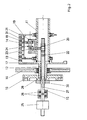
- FIG. 2 The detailed structure of the arranged between the frame walls 10 of the printing press Storage drum 5 is shown in FIG. 2.
- the storage drum 5 comprises a drum base body 11, on which the sheet holding systems 8 for the front area and front sheet support segments 13 are arranged, and a carrier body 19, which carries the sheet holding systems 9 for the rear area and rear sheet support segments 14. Viewed in the axial direction, the front and rear arch support segments 13, 14 are arranged alternately, so that when the support body 19 is rotated relative to the drum base body 11 they slide into one another in a rake-like manner and form the lateral surface of the storage drum 5 on which the sheets 7 are guided.
- the basic drum body 11 comprises a hollow cylindrical shaft, which has hollow cylindrical shaft journals 12 at its two ends, the diameter of which is smaller than the diameter of the hollow cylindrical shaft.
- Rolling bearings are arranged on the shaft journal, via which the drum base body 11 is rotatably mounted in the frame walls 10.
- a drive gear 16 is provided on one of the shaft journals 12, via which the main drum body 11 and thus the storage drum 5 are driven.
- a sleeve 28 is inserted into the interior of the hollow cylindrical shaft, in which a push rod 15 is mounted coaxially displaceable to the central longitudinal axis of the hollow cylindrical shaft 12.
- the sleeve 28 has a collar 30 which bears against the end face of the one shaft journal 12 and is held in this position by screw connections.
- An anti-rotation device 27 is formed between the sleeve 28 and the push rod 15.
- an area of the push rod 15 is designed as a toothed rack 22.
- the pinion of a pinion shaft 20 engages in the toothing of the toothed rack 22 and is in turn rotatably mounted to the drum base body 11.
- the pinion shaft 20 extends approximately in the radial direction to the hollow cylindrical shaft and passes through its outer surface.
- On its end facing away from the pinion it carries a first bevel gear 23 which meshes with a second bevel gear 24 which is arranged on a rotatably mounted shaft 21 which extends parallel to the axis of rotation of the drum base body 11.
- a bearing block is provided which is attached to the outer radius of the hollow cylindrical shaft.
- the shaft 21 carries a spur gear 31 which engages in a toothed segment 18 which is fixedly connected to the carrier body 19.
- the first and the second bevel gear 23, 24 and the spur gear 31 are arranged in a rotationally fixed manner on the pinion shaft 20 and the shaft 21, respectively.
- a drive 25 in the form of a linear motor, Pneumatic cylinder or an electric motor connected to a screw jack formed with which a linear actuation movement can be generated.
- a rotary decoupler which consists of two axial bearings 26 connected to one another via a common housing is formed.
- a sensor not shown, with which the position of the same and thus the format adjustment of the sheet holding systems 8, 9 is detectable.
- the push rod 15 is from the Drive 25 in the sleeve 28 inserted into the drum base body 11 along the central longitudinal axis of the drum body 11 shifted.
- the Pinion shaft 20 in a rotational movement, which is via the first and the second bevel gear 23, 24 is transmitted to the shaft 21.
- the spur gear 31 arranged on the shaft 21 is offset via the toothed segment 18 the carrier body 19 relative to the drum base body 11 in a rotary motion.
- the invention was described using the example of a storage drum. However, it is also on sheet-guiding drums in pure face printing machines for the Guide of the bow 7 can be used in the rear area, especially when the drums are double-sized.
Landscapes
- Feeding Of Articles By Means Other Than Belts Or Rollers (AREA)
- Rotary Presses (AREA)
Applications Claiming Priority (2)
| Application Number | Priority Date | Filing Date | Title |
|---|---|---|---|
| DE10260760 | 2002-12-23 | ||
| DE2002160760 DE10260760A1 (de) | 2002-12-23 | 2002-12-23 | Einrichtung zur Formatverstellung an bogenführenden Trommeln von Bogendruckmaschinen |
Publications (3)
| Publication Number | Publication Date |
|---|---|
| EP1433601A2 true EP1433601A2 (fr) | 2004-06-30 |
| EP1433601A3 EP1433601A3 (fr) | 2004-11-17 |
| EP1433601B1 EP1433601B1 (fr) | 2006-02-15 |
Family
ID=32404221
Family Applications (1)
| Application Number | Title | Priority Date | Filing Date |
|---|---|---|---|
| EP20030026102 Expired - Lifetime EP1433601B1 (fr) | 2002-12-23 | 2003-11-13 | Dispositif de réglage du repérage des tambours de transfert de feuilles sur machine d'impression recto-verso |
Country Status (2)
| Country | Link |
|---|---|
| EP (1) | EP1433601B1 (fr) |
| DE (2) | DE10260760A1 (fr) |
Family Cites Families (3)
| Publication number | Priority date | Publication date | Assignee | Title |
|---|---|---|---|---|
| DE2460503C3 (de) * | 1974-12-20 | 1979-05-03 | Heidelberger Druckmaschinen Ag, 6900 Heidelberg | Umstell- und Einstellvorrichtung einer Übergabetrommel zur Bogenüberführung |
| DE3911630A1 (de) * | 1989-04-10 | 1990-10-11 | Heidelberger Druckmasch Ag | Vorrichtung zur formatverstellung an bogenfuehrungstrommeln einer druckmaschine |
| DE4322477C2 (de) * | 1992-07-15 | 1995-12-21 | Heidelberger Druckmasch Ag | Verfahren und Einrichtung zum An- und Abstellen der Bogenwendung und zur Formateinstellung bei der Förderung von Bogen durch eine Druckmaschine |
-
2002
- 2002-12-23 DE DE2002160760 patent/DE10260760A1/de not_active Withdrawn
-
2003
- 2003-11-13 DE DE50302417T patent/DE50302417D1/de not_active Expired - Lifetime
- 2003-11-13 EP EP20030026102 patent/EP1433601B1/fr not_active Expired - Lifetime
Also Published As
| Publication number | Publication date |
|---|---|
| EP1433601B1 (fr) | 2006-02-15 |
| DE50302417D1 (de) | 2006-04-20 |
| DE10260760A1 (de) | 2004-07-08 |
| EP1433601A3 (fr) | 2004-11-17 |
Similar Documents
| Publication | Publication Date | Title |
|---|---|---|
| DE2818662C2 (de) | Vorrichtung zum Einstellen des Seiten- und Umfangsregisters eines Plattenzylinders einer Rotationsdruckmaschine | |
| EP0741015B1 (fr) | Dispositif pour régler la position circonférentielle et latérale du cylindre porte-plaque | |
| DE3110468A1 (de) | Antrieb fuer funktionsgruppen in bogenfuehrungszylindern von druckmaschinen | |
| DE102009001475B4 (de) | Druckeinheit einer Druckmaschine mit mindestens einem Druckwerk | |
| CH694045A5 (de) | Zylinder einer Rotationsdruckmaschine. | |
| DE3911630C2 (fr) | ||
| EP1125734A1 (fr) | Dispositif d'entraínement de cylindres d'impression | |
| DE2901236A1 (de) | Vorrichtung zum verstellen des antriebes an bogenrotationsdruckmaschinen fuer wahlweisen schoen- oder schoen- und widerdruck | |
| EP1433598B1 (fr) | Dispositif de réglage du repérage des tambours de transfert de feuilles sur machine d'impression recto-verso | |
| EP1433601B1 (fr) | Dispositif de réglage du repérage des tambours de transfert de feuilles sur machine d'impression recto-verso | |
| DE10260758B3 (de) | Einrichtung zur Formatverstellung an bogenführenden Trommeln von Bogendruckmaschinen | |
| EP1742795B1 (fr) | Entrainement direct pour un cylindre d'une machine de transformation | |
| EP1336481B1 (fr) | Dispositif de commutation de la commande des pinces d'un cylindre à pinces | |
| EP1433600B1 (fr) | Dispositif de réglage du repérage des tambours de transfert de feuilles sur machine d'impression recto-verso | |
| DE102005018677A1 (de) | Antrieb für eine Verarbeitungsmaschine und Verfahren zum Antreiben einer Verarbeitungsmaschine | |
| DE10158484A1 (de) | Einstellvorrichtung einer Bogenrotationsdruckmaschine | |
| EP1256446B1 (fr) | Système réglable de pinces sur un tambour collecteur | |
| DE2708478A1 (de) | Uebergabe- und wendetrommel fuer eine bogenrotationsdruckmaschine | |
| DE10122227B4 (de) | Speichertrommel in Wendeeinrichtungen von Bogendruckmaschinen | |
| DE10260759A1 (de) | Einrichtung zur Formatverstellung an bogenführenden Trommeln von Bogendruckmaschinen | |
| DE10219001B4 (de) | Einrichtung zum Bogenbremsen in einer Druckmaschine | |
| DE10254113A1 (de) | Vorrichtung zur Änderung des Betriebszustands einer Greifersteuereinrichtung in einer Bogenwendeeinrichtung einer bogenverarbeitenden Maschine | |
| WO2011061050A1 (fr) | Machine de traitement pour matériau en feuille | |
| DE10152838B4 (de) | Verfahren zum Betreiben einer Bogenrotationsdruckmaschine und Bogenrotationsdruckmaschine | |
| EP1439060B1 (fr) | Dispositif de réglage du repérage des tambours de transfert de feuilles sur machine d'impression recto-verso |
Legal Events
| Date | Code | Title | Description |
|---|---|---|---|
| PUAI | Public reference made under article 153(3) epc to a published international application that has entered the european phase |
Free format text: ORIGINAL CODE: 0009012 |
|
| AK | Designated contracting states |
Kind code of ref document: A2 Designated state(s): AT BE BG CH CY CZ DE DK EE ES FI FR GB GR HU IE IT LI LU MC NL PT RO SE SI SK TR |
|
| AX | Request for extension of the european patent |
Extension state: AL LT LV MK |
|
| PUAL | Search report despatched |
Free format text: ORIGINAL CODE: 0009013 |
|
| AK | Designated contracting states |
Kind code of ref document: A3 Designated state(s): AT BE BG CH CY CZ DE DK EE ES FI FR GB GR HU IE IT LI LU MC NL PT RO SE SI SK TR |
|
| AX | Request for extension of the european patent |
Extension state: AL LT LV MK |
|
| 17P | Request for examination filed |
Effective date: 20041025 |
|
| 17Q | First examination report despatched |
Effective date: 20050315 |
|
| AKX | Designation fees paid |
Designated state(s): DE FR GB IT |
|
| GRAP | Despatch of communication of intention to grant a patent |
Free format text: ORIGINAL CODE: EPIDOSNIGR1 |
|
| GRAS | Grant fee paid |
Free format text: ORIGINAL CODE: EPIDOSNIGR3 |
|
| GRAA | (expected) grant |
Free format text: ORIGINAL CODE: 0009210 |
|
| AK | Designated contracting states |
Kind code of ref document: B1 Designated state(s): DE FR GB IT |
|
| PG25 | Lapsed in a contracting state [announced via postgrant information from national office to epo] |
Ref country code: IT Free format text: LAPSE BECAUSE OF FAILURE TO SUBMIT A TRANSLATION OF THE DESCRIPTION OR TO PAY THE FEE WITHIN THE PRESCRIBED TIME-LIMIT;WARNING: LAPSES OF ITALIAN PATENTS WITH EFFECTIVE DATE BEFORE 2007 MAY HAVE OCCURRED AT ANY TIME BEFORE 2007. THE CORRECT EFFECTIVE DATE MAY BE DIFFERENT FROM THE ONE RECORDED. Effective date: 20060215 |
|
| REG | Reference to a national code |
Ref country code: GB Ref legal event code: FG4D Free format text: NOT ENGLISH |
|
| REF | Corresponds to: |
Ref document number: 50302417 Country of ref document: DE Date of ref document: 20060420 Kind code of ref document: P |
|
| GBT | Gb: translation of ep patent filed (gb section 77(6)(a)/1977) |
Effective date: 20060523 |
|
| ET | Fr: translation filed | ||
| PLBE | No opposition filed within time limit |
Free format text: ORIGINAL CODE: 0009261 |
|
| STAA | Information on the status of an ep patent application or granted ep patent |
Free format text: STATUS: NO OPPOSITION FILED WITHIN TIME LIMIT |
|
| 26N | No opposition filed |
Effective date: 20061116 |
|
| PGFP | Annual fee paid to national office [announced via postgrant information from national office to epo] |
Ref country code: FR Payment date: 20141119 Year of fee payment: 12 Ref country code: GB Payment date: 20141119 Year of fee payment: 12 Ref country code: DE Payment date: 20141206 Year of fee payment: 12 |
|
| PGFP | Annual fee paid to national office [announced via postgrant information from national office to epo] |
Ref country code: IT Payment date: 20141125 Year of fee payment: 12 |
|
| REG | Reference to a national code |
Ref country code: DE Ref legal event code: R081 Ref document number: 50302417 Country of ref document: DE Owner name: KOENIG & BAUER AG, DE Free format text: FORMER OWNER: KOENIG & BAUER AKTIENGESELLSCHAFT, 97080 WUERZBURG, DE |
|
| REG | Reference to a national code |
Ref country code: DE Ref legal event code: R119 Ref document number: 50302417 Country of ref document: DE |
|
| GBPC | Gb: european patent ceased through non-payment of renewal fee |
Effective date: 20151113 |
|
| PG25 | Lapsed in a contracting state [announced via postgrant information from national office to epo] |
Ref country code: IT Free format text: LAPSE BECAUSE OF NON-PAYMENT OF DUE FEES Effective date: 20151113 |
|
| REG | Reference to a national code |
Ref country code: FR Ref legal event code: ST Effective date: 20160729 |
|
| PG25 | Lapsed in a contracting state [announced via postgrant information from national office to epo] |
Ref country code: DE Free format text: LAPSE BECAUSE OF NON-PAYMENT OF DUE FEES Effective date: 20160601 Ref country code: GB Free format text: LAPSE BECAUSE OF NON-PAYMENT OF DUE FEES Effective date: 20151113 |
|
| PG25 | Lapsed in a contracting state [announced via postgrant information from national office to epo] |
Ref country code: FR Free format text: LAPSE BECAUSE OF NON-PAYMENT OF DUE FEES Effective date: 20151130 |