EP1433641A1 - Appareil de commande de transmission pour véhicule hybride - Google Patents
Appareil de commande de transmission pour véhicule hybride Download PDFInfo
- Publication number
- EP1433641A1 EP1433641A1 EP03029614A EP03029614A EP1433641A1 EP 1433641 A1 EP1433641 A1 EP 1433641A1 EP 03029614 A EP03029614 A EP 03029614A EP 03029614 A EP03029614 A EP 03029614A EP 1433641 A1 EP1433641 A1 EP 1433641A1
- Authority
- EP
- European Patent Office
- Prior art keywords
- motor
- engine
- propulsion mode
- mode
- drive
- Prior art date
- Legal status (The legal status is an assumption and is not a legal conclusion. Google has not performed a legal analysis and makes no representation as to the accuracy of the status listed.)
- Granted
Links
Images





Classifications
-
- B—PERFORMING OPERATIONS; TRANSPORTING
- B60—VEHICLES IN GENERAL
- B60K—ARRANGEMENT OR MOUNTING OF PROPULSION UNITS OR OF TRANSMISSIONS IN VEHICLES; ARRANGEMENT OR MOUNTING OF PLURAL DIVERSE PRIME-MOVERS IN VEHICLES; AUXILIARY DRIVES FOR VEHICLES; INSTRUMENTATION OR DASHBOARDS FOR VEHICLES; ARRANGEMENTS IN CONNECTION WITH COOLING, AIR INTAKE, GAS EXHAUST OR FUEL SUPPLY OF PROPULSION UNITS IN VEHICLES
- B60K6/00—Arrangement or mounting of plural diverse prime-movers for mutual or common propulsion, e.g. hybrid propulsion systems comprising electric motors and internal combustion engines
- B60K6/20—Arrangement or mounting of plural diverse prime-movers for mutual or common propulsion, e.g. hybrid propulsion systems comprising electric motors and internal combustion engines the prime-movers consisting of electric motors and internal combustion engines, e.g. HEVs
- B60K6/42—Arrangement or mounting of plural diverse prime-movers for mutual or common propulsion, e.g. hybrid propulsion systems comprising electric motors and internal combustion engines the prime-movers consisting of electric motors and internal combustion engines, e.g. HEVs characterised by the architecture of the hybrid electric vehicle
- B60K6/44—Series-parallel type
-
- B—PERFORMING OPERATIONS; TRANSPORTING
- B60—VEHICLES IN GENERAL
- B60W—CONJOINT CONTROL OF VEHICLE SUB-UNITS OF DIFFERENT TYPE OR DIFFERENT FUNCTION; CONTROL SYSTEMS SPECIALLY ADAPTED FOR HYBRID VEHICLES; ROAD VEHICLE DRIVE CONTROL SYSTEMS FOR PURPOSES NOT RELATED TO THE CONTROL OF A PARTICULAR SUB-UNIT
- B60W20/00—Control systems specially adapted for hybrid vehicles
- B60W20/40—Controlling the engagement or disengagement of prime movers, e.g. for transition between prime movers
-
- B—PERFORMING OPERATIONS; TRANSPORTING
- B60—VEHICLES IN GENERAL
- B60K—ARRANGEMENT OR MOUNTING OF PROPULSION UNITS OR OF TRANSMISSIONS IN VEHICLES; ARRANGEMENT OR MOUNTING OF PLURAL DIVERSE PRIME-MOVERS IN VEHICLES; AUXILIARY DRIVES FOR VEHICLES; INSTRUMENTATION OR DASHBOARDS FOR VEHICLES; ARRANGEMENTS IN CONNECTION WITH COOLING, AIR INTAKE, GAS EXHAUST OR FUEL SUPPLY OF PROPULSION UNITS IN VEHICLES
- B60K6/00—Arrangement or mounting of plural diverse prime-movers for mutual or common propulsion, e.g. hybrid propulsion systems comprising electric motors and internal combustion engines
- B60K6/20—Arrangement or mounting of plural diverse prime-movers for mutual or common propulsion, e.g. hybrid propulsion systems comprising electric motors and internal combustion engines the prime-movers consisting of electric motors and internal combustion engines, e.g. HEVs
- B60K6/42—Arrangement or mounting of plural diverse prime-movers for mutual or common propulsion, e.g. hybrid propulsion systems comprising electric motors and internal combustion engines the prime-movers consisting of electric motors and internal combustion engines, e.g. HEVs characterised by the architecture of the hybrid electric vehicle
- B60K6/44—Series-parallel type
- B60K6/442—Series-parallel switching type
-
- B—PERFORMING OPERATIONS; TRANSPORTING
- B60—VEHICLES IN GENERAL
- B60K—ARRANGEMENT OR MOUNTING OF PROPULSION UNITS OR OF TRANSMISSIONS IN VEHICLES; ARRANGEMENT OR MOUNTING OF PLURAL DIVERSE PRIME-MOVERS IN VEHICLES; AUXILIARY DRIVES FOR VEHICLES; INSTRUMENTATION OR DASHBOARDS FOR VEHICLES; ARRANGEMENTS IN CONNECTION WITH COOLING, AIR INTAKE, GAS EXHAUST OR FUEL SUPPLY OF PROPULSION UNITS IN VEHICLES
- B60K6/00—Arrangement or mounting of plural diverse prime-movers for mutual or common propulsion, e.g. hybrid propulsion systems comprising electric motors and internal combustion engines
- B60K6/20—Arrangement or mounting of plural diverse prime-movers for mutual or common propulsion, e.g. hybrid propulsion systems comprising electric motors and internal combustion engines the prime-movers consisting of electric motors and internal combustion engines, e.g. HEVs
- B60K6/50—Architecture of the driveline characterised by arrangement or kind of transmission units
- B60K6/52—Driving a plurality of drive axles, e.g. four-wheel drive
-
- B—PERFORMING OPERATIONS; TRANSPORTING
- B60—VEHICLES IN GENERAL
- B60W—CONJOINT CONTROL OF VEHICLE SUB-UNITS OF DIFFERENT TYPE OR DIFFERENT FUNCTION; CONTROL SYSTEMS SPECIALLY ADAPTED FOR HYBRID VEHICLES; ROAD VEHICLE DRIVE CONTROL SYSTEMS FOR PURPOSES NOT RELATED TO THE CONTROL OF A PARTICULAR SUB-UNIT
- B60W10/00—Conjoint control of vehicle sub-units of different type or different function
- B60W10/02—Conjoint control of vehicle sub-units of different type or different function including control of driveline clutches
-
- B—PERFORMING OPERATIONS; TRANSPORTING
- B60—VEHICLES IN GENERAL
- B60W—CONJOINT CONTROL OF VEHICLE SUB-UNITS OF DIFFERENT TYPE OR DIFFERENT FUNCTION; CONTROL SYSTEMS SPECIALLY ADAPTED FOR HYBRID VEHICLES; ROAD VEHICLE DRIVE CONTROL SYSTEMS FOR PURPOSES NOT RELATED TO THE CONTROL OF A PARTICULAR SUB-UNIT
- B60W10/00—Conjoint control of vehicle sub-units of different type or different function
- B60W10/04—Conjoint control of vehicle sub-units of different type or different function including control of propulsion units
- B60W10/06—Conjoint control of vehicle sub-units of different type or different function including control of propulsion units including control of combustion engines
-
- B—PERFORMING OPERATIONS; TRANSPORTING
- B60—VEHICLES IN GENERAL
- B60W—CONJOINT CONTROL OF VEHICLE SUB-UNITS OF DIFFERENT TYPE OR DIFFERENT FUNCTION; CONTROL SYSTEMS SPECIALLY ADAPTED FOR HYBRID VEHICLES; ROAD VEHICLE DRIVE CONTROL SYSTEMS FOR PURPOSES NOT RELATED TO THE CONTROL OF A PARTICULAR SUB-UNIT
- B60W10/00—Conjoint control of vehicle sub-units of different type or different function
- B60W10/04—Conjoint control of vehicle sub-units of different type or different function including control of propulsion units
- B60W10/08—Conjoint control of vehicle sub-units of different type or different function including control of propulsion units including control of electric propulsion units, e.g. motors or generators
-
- B—PERFORMING OPERATIONS; TRANSPORTING
- B60—VEHICLES IN GENERAL
- B60W—CONJOINT CONTROL OF VEHICLE SUB-UNITS OF DIFFERENT TYPE OR DIFFERENT FUNCTION; CONTROL SYSTEMS SPECIALLY ADAPTED FOR HYBRID VEHICLES; ROAD VEHICLE DRIVE CONTROL SYSTEMS FOR PURPOSES NOT RELATED TO THE CONTROL OF A PARTICULAR SUB-UNIT
- B60W20/00—Control systems specially adapted for hybrid vehicles
-
- B—PERFORMING OPERATIONS; TRANSPORTING
- B60—VEHICLES IN GENERAL
- B60L—PROPULSION OF ELECTRICALLY-PROPELLED VEHICLES; SUPPLYING ELECTRIC POWER FOR AUXILIARY EQUIPMENT OF ELECTRICALLY-PROPELLED VEHICLES; ELECTRODYNAMIC BRAKE SYSTEMS FOR VEHICLES IN GENERAL; MAGNETIC SUSPENSION OR LEVITATION FOR VEHICLES; MONITORING OPERATING VARIABLES OF ELECTRICALLY-PROPELLED VEHICLES; ELECTRIC SAFETY DEVICES FOR ELECTRICALLY-PROPELLED VEHICLES
- B60L2240/00—Control parameters of input or output; Target parameters
- B60L2240/40—Drive Train control parameters
- B60L2240/44—Drive Train control parameters related to combustion engines
- B60L2240/445—Temperature
-
- B—PERFORMING OPERATIONS; TRANSPORTING
- B60—VEHICLES IN GENERAL
- B60L—PROPULSION OF ELECTRICALLY-PROPELLED VEHICLES; SUPPLYING ELECTRIC POWER FOR AUXILIARY EQUIPMENT OF ELECTRICALLY-PROPELLED VEHICLES; ELECTRODYNAMIC BRAKE SYSTEMS FOR VEHICLES IN GENERAL; MAGNETIC SUSPENSION OR LEVITATION FOR VEHICLES; MONITORING OPERATING VARIABLES OF ELECTRICALLY-PROPELLED VEHICLES; ELECTRIC SAFETY DEVICES FOR ELECTRICALLY-PROPELLED VEHICLES
- B60L2240/00—Control parameters of input or output; Target parameters
- B60L2240/40—Drive Train control parameters
- B60L2240/48—Drive Train control parameters related to transmissions
- B60L2240/486—Operating parameters
-
- B—PERFORMING OPERATIONS; TRANSPORTING
- B60—VEHICLES IN GENERAL
- B60W—CONJOINT CONTROL OF VEHICLE SUB-UNITS OF DIFFERENT TYPE OR DIFFERENT FUNCTION; CONTROL SYSTEMS SPECIALLY ADAPTED FOR HYBRID VEHICLES; ROAD VEHICLE DRIVE CONTROL SYSTEMS FOR PURPOSES NOT RELATED TO THE CONTROL OF A PARTICULAR SUB-UNIT
- B60W2510/00—Input parameters relating to a particular sub-units
- B60W2510/06—Combustion engines, Gas turbines
- B60W2510/0604—Throttle position
-
- B—PERFORMING OPERATIONS; TRANSPORTING
- B60—VEHICLES IN GENERAL
- B60W—CONJOINT CONTROL OF VEHICLE SUB-UNITS OF DIFFERENT TYPE OR DIFFERENT FUNCTION; CONTROL SYSTEMS SPECIALLY ADAPTED FOR HYBRID VEHICLES; ROAD VEHICLE DRIVE CONTROL SYSTEMS FOR PURPOSES NOT RELATED TO THE CONTROL OF A PARTICULAR SUB-UNIT
- B60W2510/00—Input parameters relating to a particular sub-units
- B60W2510/06—Combustion engines, Gas turbines
- B60W2510/0671—Engine manifold pressure
-
- B—PERFORMING OPERATIONS; TRANSPORTING
- B60—VEHICLES IN GENERAL
- B60W—CONJOINT CONTROL OF VEHICLE SUB-UNITS OF DIFFERENT TYPE OR DIFFERENT FUNCTION; CONTROL SYSTEMS SPECIALLY ADAPTED FOR HYBRID VEHICLES; ROAD VEHICLE DRIVE CONTROL SYSTEMS FOR PURPOSES NOT RELATED TO THE CONTROL OF A PARTICULAR SUB-UNIT
- B60W2510/00—Input parameters relating to a particular sub-units
- B60W2510/06—Combustion engines, Gas turbines
- B60W2510/0676—Engine temperature
-
- B—PERFORMING OPERATIONS; TRANSPORTING
- B60—VEHICLES IN GENERAL
- B60W—CONJOINT CONTROL OF VEHICLE SUB-UNITS OF DIFFERENT TYPE OR DIFFERENT FUNCTION; CONTROL SYSTEMS SPECIALLY ADAPTED FOR HYBRID VEHICLES; ROAD VEHICLE DRIVE CONTROL SYSTEMS FOR PURPOSES NOT RELATED TO THE CONTROL OF A PARTICULAR SUB-UNIT
- B60W2510/00—Input parameters relating to a particular sub-units
- B60W2510/24—Energy storage means
- B60W2510/242—Energy storage means for electrical energy
- B60W2510/244—Charge state
-
- B—PERFORMING OPERATIONS; TRANSPORTING
- B60—VEHICLES IN GENERAL
- B60W—CONJOINT CONTROL OF VEHICLE SUB-UNITS OF DIFFERENT TYPE OR DIFFERENT FUNCTION; CONTROL SYSTEMS SPECIALLY ADAPTED FOR HYBRID VEHICLES; ROAD VEHICLE DRIVE CONTROL SYSTEMS FOR PURPOSES NOT RELATED TO THE CONTROL OF A PARTICULAR SUB-UNIT
- B60W2520/00—Input parameters relating to overall vehicle dynamics
- B60W2520/10—Longitudinal speed
-
- B—PERFORMING OPERATIONS; TRANSPORTING
- B60—VEHICLES IN GENERAL
- B60W—CONJOINT CONTROL OF VEHICLE SUB-UNITS OF DIFFERENT TYPE OR DIFFERENT FUNCTION; CONTROL SYSTEMS SPECIALLY ADAPTED FOR HYBRID VEHICLES; ROAD VEHICLE DRIVE CONTROL SYSTEMS FOR PURPOSES NOT RELATED TO THE CONTROL OF A PARTICULAR SUB-UNIT
- B60W2520/00—Input parameters relating to overall vehicle dynamics
- B60W2520/10—Longitudinal speed
- B60W2520/105—Longitudinal acceleration
-
- B—PERFORMING OPERATIONS; TRANSPORTING
- B60—VEHICLES IN GENERAL
- B60W—CONJOINT CONTROL OF VEHICLE SUB-UNITS OF DIFFERENT TYPE OR DIFFERENT FUNCTION; CONTROL SYSTEMS SPECIALLY ADAPTED FOR HYBRID VEHICLES; ROAD VEHICLE DRIVE CONTROL SYSTEMS FOR PURPOSES NOT RELATED TO THE CONTROL OF A PARTICULAR SUB-UNIT
- B60W2530/00—Input parameters relating to vehicle conditions or values, not covered by groups B60W2510/00 or B60W2520/00
- B60W2530/16—Driving resistance
-
- B—PERFORMING OPERATIONS; TRANSPORTING
- B60—VEHICLES IN GENERAL
- B60W—CONJOINT CONTROL OF VEHICLE SUB-UNITS OF DIFFERENT TYPE OR DIFFERENT FUNCTION; CONTROL SYSTEMS SPECIALLY ADAPTED FOR HYBRID VEHICLES; ROAD VEHICLE DRIVE CONTROL SYSTEMS FOR PURPOSES NOT RELATED TO THE CONTROL OF A PARTICULAR SUB-UNIT
- B60W2540/00—Input parameters relating to occupants
- B60W2540/10—Accelerator pedal position
-
- B—PERFORMING OPERATIONS; TRANSPORTING
- B60—VEHICLES IN GENERAL
- B60W—CONJOINT CONTROL OF VEHICLE SUB-UNITS OF DIFFERENT TYPE OR DIFFERENT FUNCTION; CONTROL SYSTEMS SPECIALLY ADAPTED FOR HYBRID VEHICLES; ROAD VEHICLE DRIVE CONTROL SYSTEMS FOR PURPOSES NOT RELATED TO THE CONTROL OF A PARTICULAR SUB-UNIT
- B60W2540/00—Input parameters relating to occupants
- B60W2540/12—Brake pedal position
-
- B—PERFORMING OPERATIONS; TRANSPORTING
- B60—VEHICLES IN GENERAL
- B60W—CONJOINT CONTROL OF VEHICLE SUB-UNITS OF DIFFERENT TYPE OR DIFFERENT FUNCTION; CONTROL SYSTEMS SPECIALLY ADAPTED FOR HYBRID VEHICLES; ROAD VEHICLE DRIVE CONTROL SYSTEMS FOR PURPOSES NOT RELATED TO THE CONTROL OF A PARTICULAR SUB-UNIT
- B60W2710/00—Output or target parameters relating to a particular sub-units
- B60W2710/06—Combustion engines, Gas turbines
-
- B—PERFORMING OPERATIONS; TRANSPORTING
- B60—VEHICLES IN GENERAL
- B60W—CONJOINT CONTROL OF VEHICLE SUB-UNITS OF DIFFERENT TYPE OR DIFFERENT FUNCTION; CONTROL SYSTEMS SPECIALLY ADAPTED FOR HYBRID VEHICLES; ROAD VEHICLE DRIVE CONTROL SYSTEMS FOR PURPOSES NOT RELATED TO THE CONTROL OF A PARTICULAR SUB-UNIT
- B60W2710/00—Output or target parameters relating to a particular sub-units
- B60W2710/06—Combustion engines, Gas turbines
- B60W2710/0616—Position of fuel or air injector
-
- B—PERFORMING OPERATIONS; TRANSPORTING
- B60—VEHICLES IN GENERAL
- B60W—CONJOINT CONTROL OF VEHICLE SUB-UNITS OF DIFFERENT TYPE OR DIFFERENT FUNCTION; CONTROL SYSTEMS SPECIALLY ADAPTED FOR HYBRID VEHICLES; ROAD VEHICLE DRIVE CONTROL SYSTEMS FOR PURPOSES NOT RELATED TO THE CONTROL OF A PARTICULAR SUB-UNIT
- B60W2710/00—Output or target parameters relating to a particular sub-units
- B60W2710/08—Electric propulsion units
-
- B—PERFORMING OPERATIONS; TRANSPORTING
- B60—VEHICLES IN GENERAL
- B60W—CONJOINT CONTROL OF VEHICLE SUB-UNITS OF DIFFERENT TYPE OR DIFFERENT FUNCTION; CONTROL SYSTEMS SPECIALLY ADAPTED FOR HYBRID VEHICLES; ROAD VEHICLE DRIVE CONTROL SYSTEMS FOR PURPOSES NOT RELATED TO THE CONTROL OF A PARTICULAR SUB-UNIT
- B60W2710/00—Output or target parameters relating to a particular sub-units
- B60W2710/10—Change speed gearings
- B60W2710/1061—Output power
-
- F—MECHANICAL ENGINEERING; LIGHTING; HEATING; WEAPONS; BLASTING
- F16—ENGINEERING ELEMENTS AND UNITS; GENERAL MEASURES FOR PRODUCING AND MAINTAINING EFFECTIVE FUNCTIONING OF MACHINES OR INSTALLATIONS; THERMAL INSULATION IN GENERAL
- F16H—GEARING
- F16H61/00—Control functions within control units of change-speed- or reversing-gearings for conveying rotary motion ; Control of exclusively fluid gearing, friction gearing, gearings with endless flexible members or other particular types of gearing
- F16H61/66—Control functions within control units of change-speed- or reversing-gearings for conveying rotary motion ; Control of exclusively fluid gearing, friction gearing, gearings with endless flexible members or other particular types of gearing specially adapted for continuously variable gearings
- F16H61/662—Control functions within control units of change-speed- or reversing-gearings for conveying rotary motion ; Control of exclusively fluid gearing, friction gearing, gearings with endless flexible members or other particular types of gearing specially adapted for continuously variable gearings with endless flexible members
-
- Y—GENERAL TAGGING OF NEW TECHNOLOGICAL DEVELOPMENTS; GENERAL TAGGING OF CROSS-SECTIONAL TECHNOLOGIES SPANNING OVER SEVERAL SECTIONS OF THE IPC; TECHNICAL SUBJECTS COVERED BY FORMER USPC CROSS-REFERENCE ART COLLECTIONS [XRACs] AND DIGESTS
- Y02—TECHNOLOGIES OR APPLICATIONS FOR MITIGATION OR ADAPTATION AGAINST CLIMATE CHANGE
- Y02T—CLIMATE CHANGE MITIGATION TECHNOLOGIES RELATED TO TRANSPORTATION
- Y02T10/00—Road transport of goods or passengers
- Y02T10/60—Other road transportation technologies with climate change mitigation effect
- Y02T10/62—Hybrid vehicles
Definitions
- the present invention relates to a drive control apparatus for a hybrid vehicle whose drive shaft is rotated by an engine and an electric motor, and more particularly to a drive control apparatus for a hybrid vehicle which has two motors for applying drive force (torque) to front and rear wheels of the hybrid vehicle.
- hybrid vehicles having drive wheels rotated by an internal combustion engine and an electric motor have been widely developed.
- the hybrid vehicle operates in various modes including a so-called EV (Electric Vehicle) mode, in which the engine is disabled and the hybrid vehicle is run only by the motor, for reducing fuel consumption by the engine.
- EV Electric Vehicle
- the hybrid vehicle needs a greater torque, or the electric power remaining in a battery on the hybrid vehicle is low, the engine is started. At this time, the battery is required to supply electric power large enough to start the engine. Therefore, it is necessary to monitor the electric power that remains in the battery, and to control the drive power of the motor, taking into account the electric power that is needed to start the engine.
- the motor On the hybrid vehicle, the motor may be operated in a regenerative mode as an electric generator for charging the battery.
- the motor When the motor generates electric power in the regenerative mode, it is desirable to distribute as much drive power as possible from the drive wheels to the motor, and any resistance to intake air and exhaust emission of the engine should be small.
- a technique for disabling engine cylinders by inactivating intake and exhaust valves of the engine cylinders see, for example, Japanese laid-open patent publication No. 2002-201972. According to the proposed technique, a sufficient amount of regenerated electric power can be obtained, an optimum exhaust gas control process is not adversely affected, and fuel consumption is improved.
- the propulsive motor is supplied with electric power from a high-voltage battery
- the starter motor is supplied with electric power from a low-voltage battery. Since the low-voltage battery also supplies electric power to a propulsion controller other than the starter motor, when the engine is started, the voltage across the low-voltage battery drops, possibly affecting the operation of the propulsion controller. Further, with the system disclosed in Japanese patent No. 2,973,797, the engine cannot be started while the hybrid vehicle is running.
- the high-voltage battery is used to start the engine, then the voltage across the low-voltage battery does not drop when the engine is started.
- the electric power that can be supplied to the propulsive motor is equal to the difference between the total electric power that can be supplied from the high-voltage battery and the electric power that is required to start the engine. Therefore, a speed range in which the hybrid vehicle can travel in the EV mode, i.e., a rotational speed range of the propulsive motor, is relatively narrow, making it difficult for the hybrid vehicle to give its expected performance sufficiently.
- Another object of the present invention is to provide a drive control apparatus for increasing a motor propulsion range of a hybrid vehicle to allow the hybrid vehicle to cruise and accelerate in an electric vehicle mode, for thereby reducing fuel consumption.
- Still another object of the present invention is to provide a drive control apparatus for smoothly switching between different modes of a hybrid vehicle and preventing an engine rotational speed from varying depending on the load on the hybrid vehicle.
- a drive control apparatus for a hybrid vehicle comprises a first motor coupled to a rotational shaft of an engine, a first drive wheel for receiving drive power from the rotational shaft through first clutches , a second motor, a second drive wheel for receiving drive power from the second motor, a first battery for supplying electric power to the first motor and the second motor, and a controller for controlling the first motor, the second motor, the first clutches, and the engine, wherein the controller controls an electric vehicle mode in which the first clutches are disengaged, the supply of fuel to the engine is stopped, and the second motor drives the second drive wheel to propel the hybrid vehicle, and the electric vehicle mode is at least divided into a first propulsion mode and a second propulsion mode, the first propulsion mode is a mode in which the first motor is de-energized, and the second propulsion mode is a mode in which a load imposed on the second motor is greater than in the first propulsion mode, and the first motor is supplied with electric power to rotate the rotational shaft at a predetermined speed.
- the electric vehicle mode is controlled as the first propulsion mode, in which the first motor is de-energized, and the second propulsion mode, in which the first motor is rotated at a predetermined speed, a range in which the hybrid vehicle is propelled in the electric vehicle mode is increased for reducing fuel consumption.
- the controller may switch between the first propulsion mode and the second propulsion mode based on drive power required to propel the hybrid vehicle, a vehicle speed, and a rotational speed and/or a torque of the second motor.
- the hybrid vehicle may be cruised or accelerated in the electric vehicle mode for further reducing fuel consumption.
- the controller may switch between the first propulsion mode and the second propulsion mode based on state of charge (SOC) of the first battery.
- SOC state of charge
- the controller may switch between the first propulsion mode and the second propulsion mode when the hybrid vehicle is cruising.
- the modes can stably be switched, and hence the control system may be simplified.
- the controller may switch between the first propulsion mode and the second propulsion mode based on vehicle speeds which allow the hybrid vehicle to achieve a predetermined acceleration with the output of the second motor.
- the controller may switch between the first propulsion mode and the second propulsion mode based on a rotational speed of the second motor which allows the hybrid vehicle to achieve a predetermined acceleration with the output of the second motor.
- the drive control apparatus may further comprise a second clutch disposed between the second motor and the second drive wheel, for being controlled by the controller, wherein the controller switches to an engine propulsion mode in which the first clutches are engaged to transmit drive power of at least one of the engine and the first motor to the first drive wheel, the second clutch being disengaged and the second motor is de-energized in the engine propulsion mode.
- the second motor does not serves as a load resistance for further reducing fuel consumption.
- the controller may equalize the sum of the drive power transmitted to the first drive wheel and the drive power transmitted to the second drive wheel to drive power required to propel the hybrid vehicle, and gradually change each of the drive power transmitted to the first drive wheel and the drive power transmitted to the second drive wheel. With this arrangement, the modes may smoothly be switched.
- the drive control apparatus may further comprise a battery usage decision unit for determining whether the first battery is not usable, wherein the controller performs the engine propulsion mode if it is judged by the battery usage decision unit that the first battery is not usable.
- the controller may equalize the sum of the drive power transmitted to the first drive wheel and the drive power transmitted to the second drive wheel to drive power required to propel the hybrid vehicle, gradually change each of the drive power transmitted to the first drive wheel and the drive power transmitted to the second drive wheel, and engage the first clutches when the output of the engine has reached a predetermined threshold after the engine has started.
- the modes can thus smoothly be switched, and the rotation of the engine is prevented from varying depending on the load.
- the controller is supplied with electric power from a second battery whose voltage is lower than the first battery, then the voltage that is supplied to the controller is not affected by operation of the first motor or the second motor.
- At least one cylinder of the engine is disabled to reduce a friction loss, a pumping loss, etc. of the engine.
- Rotation of the second motor may be reduced in speed by a gear mechanism and transmitted to the second drive wheel.
- a drive control apparatus for a hybrid vehicle according to a preferred embodiment of the present invention will be described below with reference to FIGS. 1 through 17.
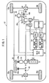
- a drive control apparatus 10 (see FIG. 3) according to the embodiment of the present invention is incorporated in a hybrid vehicle 12 (see FIG. 1).
- the hybrid vehicle 12 is a four-wheel-drive vehicle and includes an internal combustion engine 14, a first motor 16 energized by electric power supplied from a high-voltage (e.g., 144 [V]) battery (first battery) 15, a second motor 18, and a main ECU (Electronic Control Unit) 20 for centralized management and control of the engine 14, the first motor 16, the second motor 18.
- the first motor 16 may comprise a slim motor that can be connected directly to the crankshaft of the engine 14.
- the main ECU 20 comprises a microcomputer (not shown) made up of a RAM (Random Access Memory), a ROM (Read Only Memory), a CPU (Central Processing Unit), an input/output interface, a timer, and other components.
- the main ECU 20 performs its processing operation according to programs, maps, data, etc. that are stored in the ROM.
- the main ECU 20 can operate in various different manners by changing programs.
- the hybrid vehicle 12 also has first and second PDUs (Power Drive Units) 22, 24 for controlling electric power supplied to the first and second motors 16, 18, respectively, two front wheels 26a that can be driven by the engine 14 and the first motor 16, and two rear wheels 26b that can be driven by the second motor 18.
- the first PDU 22 and the second PDU 24 have functions to detect the values of currents that are supplied to the first motor 16 and the second motor 18, respectively.
- the crankshaft of the engine 14 and the first motor 16 are connected to a common rotational shaft 28, and drive the front wheels 26a through an oil pump 32, a belt-and-pulley mechanism 36, two front clutches (first clutches) 38a, 38b connected respectively to input and output ends of the belt-and-pulley mechanism 36, a gear mechanism 40, and a first differential gear 42.
- the front clutches 38a, 38b may be replaced with a vehicle starting clutch or a forward/reverse selector clutch.
- the oil pump 32 functions as a hydraulic pressure source for hydraulic devices that are employed by the belt-and-pulley mechanism 36.
- the second motor 18 drives the rear wheels 26b through a rear clutch (second clutch) 46, a rotational shaft 47, and a second differential gear 48.
- Gear mechanisms 49a, 49b are connected respectively to input and output ends of the rear clutch 46.
- the first motor 16 and the second motor 18 also operate as generators under the control of the first PDU 22 and the second PDU 24. Specifically, the first motor 16 can be rotated by drive power supplied from the engine 14 or the front wheels 26a to generate electric power, which is stored in the battery 15. The second motor 18 can be rotated by drive power supplied from the rear wheels 26b to regenerate electric power, which is also stored in the battery 15.
- the front wheels 26a and the rear wheels 26b are provided with respective vehicle speed sensors 50 which are connected to the main ECU 20 for detecting a vehicle speed V of the hybrid vehicle.
- the voltage across the battery 15 is dropped by a downverter (D ⁇ V) 51a to a voltage of 12 V that is supplied to charge a low-voltage battery (second battery) 51b.
- the low-voltage battery 51b supplies electric power to electric devices other than the drive system of the hybrid vehicle, i.e., a controller such as the ECU 20, and other devices such as illuminating units, audio devices.
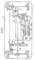
- a two-speed-switching gear mechanism 51 for switching between a high-speed gear HI and a low-speed gear LO, and a rear clutch 46b connected to the high-speed gear HI and the low-speed gear LO may be connected between the second motor 18 and the rear wheels 26b.
- the rear clutch 46b may be connected and disconnected to the high-speed gear HI and the low-speed gear L depending on the vehicle speed V and the load on the second motor 18.
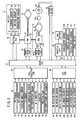
- the drive control apparatus 10 includes the main ECU 20, and has a battery ECU 52 for controlling the battery 15, a front motor ECU 54 for controlling the first motor 16 through the first PDU 22, a rear motor ECU 56 for controlling the second motor 18 through the second PDU 24, a throttle ECU 60 for controlling a throttle valve opening of the engine 14 through a DBW driver 58, a fuel injection ECU 62 for controlling an injected amount of fuel, a clutch driver 64 for engaging and disengaging the rear clutch 46, and a continuously variable transmission (CVT) ECU 66 for controlling the belt-and-pulley mechanism 36.
- a clutch switch 68 for detecting when the rear clutch 46 is engaged and disengaged is mounted on the rear clutch 46, and is connected to the clutch driver 64.
- the battery ECU 52 is connected to three sensors associated with the battery 15, i.e., a current sensor 70, a voltage sensor 72, and a temperature sensor 74.
- the current sensor 70 measures a current Ib that charges and discharges the battery 15.
- the voltage sensor 72 measures a voltage Vb of the cell chamber of the battery 15.
- the temperature sensor 74 measures a temperature Tb in, for example, the cell chamber of the battery 15.
- the battery ECU 52 calculates state of charge (SOC) of the battery 15 based on an integrated value of the voltage, or charged and discharged energy of the battery 15.
- SOC state of charge
- the SOC is represented by a numerical value in the range of 0 to 100 %.
- the SOC is 0 %, the battery 15 is in a fully discharged state or an uncharged state.
- the SOC is 100 %, the battery 15 is in a rated charged state.
- a TDC (Top Dead Center) sensor 76 for detecting a camshaft rotational angle
- a MAP sensor 78 for detecting an intake air pressure
- a steering angle sensor 79 for detecting a steering angle of the crankshaft of the engine 14
- a TA (Temperature of Air) sensor 80 for detecting an intake air temperature
- a coolant temperature sensor 82 for detecting an engine coolant temperature
- an oil temperature sensor 84 for detecting an engine oil temperature
- an M ⁇ P (Master Power) monitor 86 for detecting a brake master power negative pressure.
- an injector 88 serving as a fuel injection actuator for each of the cylinders of the engine 14
- an ignition plug 90 serving as a fuel ignition actuator for each of the cylinders of the engine 14
- a cylinder disabling solenoid 92 for selectively disabling the cylinders of the engine 14.
- a DR rotation sensor 94 for detecting a drive pulley rotational speed of the belt-and-pulley mechanism 36
- a DN rotation sensor 96 for detecting a driven pulley rotational speed of the belt-and-pulley mechanism 36
- a shift position switch 98 for detecting a shift lever position.
- a DR linear solenoid 100 for positioning a drive pulley of the belt-and-pulley mechanism 36
- DN linear solenoid 102 for positioning a driven pulley of the belt-and-pulley mechanism 36
- first front clutch solenoid 104 and a second front clutch solenoid 106 for engaging and disengaging the two front clutches 38a, 38b, respectively.
- an accelerator sensor 108 for detecting the displacement AP of the accelerator pedal of the hybrid vehicle 12
- a throttle sensor 110 for detecting a throttle valve opening
- the vehicle speed sensors 50 for detecting when the brake system of the hybrid vehicle 12 is turned on and off.
- the second motor 18 is provided with a motor temperature sensor 116 for detecting the temperature Tm thereof.
- the second PDU 24 is provided with a PDU temperature sensor 118 for detecting the temperature Tp thereof.
- the motor temperature sensor 116 and the PDU temperature sensor 118 are connected to the rear motor ECU 56.
- the motor temperature sensor 116, the PDU temperature sensor 118, and the temperature sensor 74 may be located in thermally weakest regions or positions where the temperatures of thermally weakest regions can be estimated.
- the motor temperature sensor 116 may detect the temperature of windings of the second motor 18, and the PDU temperature sensor 118 may comprise an on-chip sensor of a semiconductor device. Temperature data produced as detected results from the motor temperature sensor 116 and the PDU temperature sensor 118 are also supplied to the main ECU 20.
- the main ECU 20 switches between two modes, i.e., an EV mode and an engine propulsion mode, and controls the engine 14, the first motor 16, the second motor 18, the front clutches 38a, 38b, and the rear clutch 46 according to one of the selected modes.
- two modes i.e., an EV mode and an engine propulsion mode
- the main ECU 20 disengages the front clutches 38a, 38b and engages the rear clutch 46, propelling the hybrid vehicle with only the drive power produced by the second motor 18. At the same time, the main ECU 20 cuts off the supply of fuel to disable the engine 14.
- the main ECU 20 supplies fuel to the engine 14 and engages the clutches 38a, 38b apply drive power from the engine 14, thus propelling the hybrid vehicle.
- the EV mode is divided into a first propulsion mode and a second propulsion mode.
- the first propulsion mode is a mode for stopping the supply of electric power to the first motor 16.
- the second propulsion mode is a mode for supplying electric power to the first motor 16 to rotate the rotational shaft 28 at a predetermined speed, and disabling at least one of the cylinders of the engine 14.
- the rotational shaft 28 is placed under no load, and rotates idly.
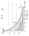
- the main ECU 20 switches between the first propulsion mode and the second propulsion mode based on a mode switching map 120 shown in FIG. 4. By disabling a cylinder, for example, at least one of the intake and exhaust valves of the cylinder is kept closed, thus reducing a friction loss and a pumping loss of the engine 14.
- the mode switching map 120 has a first threshold M1, a second threshold M2, and a resistance curve based on the vehicle speed V and the torque of the second motor 18.
- the first threshold M1 and the second threshold M2 are established such that the torque of the second motor 18 is substantially inversely proportional to the vehicle speed V.
- the first threshold M1 is smaller than the second threshold M2.
- the resistance curve L represents a running resistance corresponding to the vehicle speed V at the time the hybrid vehicle 12 runs on a road with 0 % gradient, and gradually rises in line with the vehicle speed V.
- the first propulsion mode is represented by a crosshatched area 122 above the resistance curve L and below the first threshold M1.
- the second propulsion mode is represented by a hatched area 124 above the resistance curve L and the first threshold M1, and below the second threshold M2.
- the engine propulsion mode is performed in an area 126 above the second threshold M2.
- the engine 14 In the engine propulsion mode, basically, the engine 14 is operated. However, depending on the situation in which the hybrid vehicle 12 travels, at least one of the engine 14 and the first motor 16 may drive the front wheels 16a.
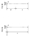
- the electric power that the battery 15 can supply is represented by Pb and the electric power with which the first motor 16 rotates the rotational shaft 28 idly is represented by Pf1
- Values of the torque [N ⁇ m], i.e., the second threshold M2, at values of the vehicle speed V are determined based on the electric power Pr.
- the electric power Pf1 is of a very small value, just large enough to rotate the rotational shaft 28 and the crankshaft of the engine 14.
- the pumping loss and the friction loss of the engine 14 can be reduced.
- the energy required to accelerate the hybrid vehicle 12 can be reduced. Accordingly, the electric power Pf1 can be made smaller.
- the electric power that is required instantaneously to start the engine 14 is represented by Pf2
- Values of the torque [N ⁇ m], i.e., the first threshold M1 at values of the vehicle speed V are determined based on the electric power Pr.
- the electric power Pf2 is greater than the electric power Pf1, thus limiting the electric power Pr that is supplied to the second motor 18. Consequently, the values of the first threshold M1 are set so as to be smaller than the values of the second threshold M2 (see FIG. 4).
- the mode switching map 120 uses three parameters, i.e., the vehicle speed V, the torque of the second motor 18, and the SOC.
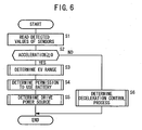
- the program is stored in the ROM, and is repeatedly executed in a predetermined minimal period of time by the CPU.
- the main ECU 20 reads detected values of the various sensors that are connected to the main ECU 20 in step S1. Specifically, the main ECU 20 reads, for example, detected values of the vehicle speed V, the SOC, the temperature Tm of the second motor 18, the temperature Tp of the second PDU 24, the temperature Tb of the battery 15 and supply current of the battery 15.
- step S2 the main ECU 20 determines an acceleration ⁇ by differentiating the vehicle speed V detected by the vehicle speed sensor 50. If the acceleration ⁇ is a positive value, then control goes to step S3. If the acceleration ⁇ is a negative value, then control goes to step S6.
- step S3 the main ECU 20 performs a process for determining an EV range.
- step S4 battery usage decision unit
- the main ECU 20 performs a process for judging a permission to use the battery 15.
- step S5 the main ECU 20 performs a process for determining a drive power source.
- step S6 the main ECU 20 performs a process for determining a deceleration control process. After step S5 or S6, the processing sequence shown in FIG. 6 is put to an end.
- steps S3, S4, and S5 will be described in detail below.
- the process for determining a deceleration control process in step S6 will not be described in detail below.
- step S3 the process for determining an EV range, i.e., details of the processing sequence in step S3, will be described below with reference to FIG. 7.
- step S101 the main ECU 20 determines a target drive power F based on the vehicle speed V and the accelerator pedal displacement AP (see FIG. 3).
- the target drive power F is calculated as F ⁇ f (V, AP) by a predetermined function f having the vehicle speed V and the accelerator pedal displacement AP as parameters, or is determined based on a target drive power map 128 shown in FIG. 8.
- the target drive power map 128 has six recorded levels AP1 through AP6 of the accelerator pedal displacement AP depending on the vehicle speed V. If the target drive power F is determined based on the target drive power map 128, then it is calculated by an interpolation from the actual value of the accelerator pedal displacement AP based on the recorded levels.
- step S102 the main ECU 20 determines a first threshold M1 based on the vehicle speed V and the SOC.
- the first threshold M1 is retrieved from the mode switching map 120 shown in FIG. 4 or is calculated as M1 ⁇ g (V, SOC) by a predetermined function g which returns the same value as' the mode switching map 120.
- step S103 the main ECU 20 determines a second threshold M2 based on the vehicle speed V and the SOC.
- the second threshold M2 is retrieved from the mode switching map 120 or is calculated as M2 ⁇ h (V, SOC) by a predetermined function h which returns the same value as the mode switching map 120.
- step S104 the main ECU 20 compares the target drive power F with the first threshold M1. If the target drive power F is smaller than the first threshold M1, then control goes to step S106. If the target drive power F is equal to or greater than the first threshold M1, then control goes to step S105.
- step S105 the main ECU 20 compares the target drive power F with the second threshold M2. If the target drive power F is smaller than the second threshold M2, then control goes to step S107. If the target drive power F is equal to or greater than the second threshold M2, then control goes to step S108.
- step S106 i.e., if the target drive power F is smaller than the first threshold M1, the main ECU 20 sets a flag RESEV to "1", indicating that the first motor 16 is to be de-energized, and sets a flag RISEV to "0", indicating that the first motor 16 is to rotate idly and cylinders of the engine 14 are to be disabled.
- step S107 i.e., if the target drive power F is between the first threshold M1 and the second threshold M2, the ECU 20 sets the flag RESEV to "0" and sets the flag RISEV to "1".
- step S108 i.e., if the target drive power F is equal to or greater than the second threshold M2, the ECU 20 sets the flag RESEV to "0" and sets the flag RISEV to "0".
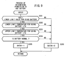
- step S4 The process for judging a permission to use the battery 15, i.e., details of the processing sequence in step S4 (see FIG. 6), will be described below with reference to FIG. 9.
- step S201 the main ECU 20 compares the SOC with a lower limit value for using the battery 15. If the SOC is greater than the lower limit value, then control goes to step S202. If the SOC is smaller than the lower limit value, then control goes to step S206.
- step S202 the main ECU 20 compares the temperature Tb (see FIG. 3) of the battery 15 with a lower limit temperature for using the battery 15. If the temperature Tb is greater than the lower limit temperature, then control goes to step S203. If the temperature Tb is smaller than the lower limit temperature, then control goes to step S206.
- step S203 the main ECU 20 compares the temperature Tb of the battery 15 with an upper limit temperature for using the battery 15. If the temperature Tb is smaller than the upper limit temperature, then control goes to step S204. If the temperature Tb is greater than the upper limit temperature, then control goes to step S206.
- step S204 the main ECU 20 determines whether the battery 15 is working normally or not. Specifically, the battery ECU 52 directly determines whether the battery 15 is working normally or not, and supplies a flag indicative of the determined result to the main ECU 20, which then confirms whether the battery 15 is working normally or not based on the supplied flag. If the battery 15 is working normally, then control goes to step S205. If the battery 15 is not working normally, then control goes to step S206. The battery ECU 52 may determine whether the battery 15 is working normally or not by detecting the voltage across the battery 15 and comparing the detected voltage with a predetermined value. If the battery 15 comprises a plurality of interconnected cells, then the battery ECU 52 may determine whether the battery 15 is working normally or not based on a voltage difference or a temperature difference between the cells.
- step S205 the main ECU 20 sets a flag BATOK to "1", indicating that the battery 15 can be used.
- the main ECU 20 sets the flag BATOK to "0", indicating that the battery 15 cannot be used.
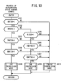
- step S5 The process for determining a drive power source, i.e., details of the processing sequence in step S5 (see FIG. 6), will be described below with reference to FIG. 10.
- step S301 the main ECU 20 confirms the value of the flag BATOK. If the value of the flag BATOK is "1", then control goes to step S302. If the value of the flag BATOK is "0”, then control goes to step S310.
- step S302 the main ECU 20 confirms the value of the flag RESEV. If the value of the flag RESEV is "1”, then control goes to step S303. If the value of the flag RESEV is "0”, then control goes to step S305.
- step S303 the main ECU 20 confirms the value of a flag FMOTOK indicative of whether the first motor 16 is working normally or not. If the value of the flag FMOTOK is "1", indicating that the first motor 16 is working normally, then control goes to step S304. If the value of the flag FMOTOK is "0”, indicating that the first motor 16 is not working normally, then control goes to step S310.
- the flag FMOTOK is set by the front motor ECU 54 and supplied to the main ECU 20.
- step S304 the main ECU 20 confirms the value of a flag RMOTOK indicative of whether the second motor 18 is working normally or not. If the value of the flag RMOTOK is "1", indicating that the second motor 18 is working normally, then control goes to step S308. If the value of the flag RMOTOK is "0”, indicating that the second motor 18 is not working normally, then control goes to step S310.
- the flag RMOTOK is set by the rear motor ECU 56 and supplied to the main ECU 20. The second motor 18 may not be working normally because of, for example, a wire disconnection, a short circuit, or an overcurrent.
- step S305 the main ECU 20 confirms the value of the flag RISEV. If the value of the flag RISEV is "1”, then control goes to step S306. If the value of the flag RISEV is "0”, then control goes to step S310.
- step S306 the main ECU 20 confirms the value of the flag FMOTOK. If the value of the flag FMOTOK is "1", then control goes to step S307. If the value of the flag FMOTOK is "0”, then control goes to step S310.
- step S307 the main ECU 20 confirms the value of the flag RMOTOK. If the value of the flag RMOTOK is "1”, then control goes to step S309. If the value of the flag RMOTOK is "0”, then control goes to step S310.
- step S308 the main ECU 20 sets up for the first propulsion mode.
- step S309 the main ECU 20 sets up for the second propulsion mode.
- step S310 the main ECU 20 sets up for the engine propulsion mode.
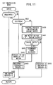
- the first propulsion mode i.e., the EV mode with the engine 14 disabled, or the processing sequence corresponding to the step S308 (see FIG. 10), will be described below with reference to FIG. 11.
- step S401 the main ECU 20 confirms a flag ENGSTPEV indicative of the first propulsion mode.
- the flag ENGSTPEV has an initial value of "0".
- step S402 the main ECU 20 sets the target drive power F for the output of the second motor 18.
- step S403 the main ECU 20 confirms a flag IDSTPEV indicative of the second propulsion mode. If the value of the flag IDSTPEV is "1", i.e., if a previous mode is the second propulsion mode, then control goes to step S404. If the value of the flag IDSTPEV is "0", i.e., if the values of both the flags IDSTPEV, ENGSTPEV are "0" and a previous mode is the engine propulsion mode, then control goes to step S406.
- step S404 the main ECU 20 instructs the front motor ECU 54 to produce the output "0" from the first motor 16.
- step S405 the main ECU 20 sets the flag ENGSTPEV to "1" and sets the flag IDSTPEV to "0".
- the main ECU 20 also sets a flag ENGDRV indicative of the engine propulsion mode to "0".
- the mode shift to the first propulsion mode is finished by the processing in step S405.
- step S406 the main ECU 20 performs a control process for reducing the output of the engine 14.
- the output of the engine 14 is set as an output value produced by, for example, subtracting a predetermined infinitesimal value from a previous output value.
- step S407 the main ECU 20 calculates an output of the second motor 18 and supplies the calculated output to the rear motor ECU 56.
- the output of the second motor 18 is set as a value produced by subtracting the output value of the engine 14 from the target drive power F.
- step S408 the main ECU 20 confirms the output value of the engine 14. If the output value of the engine 14 is substantially "0", then control goes to step S409. Otherwise, control goes to step S410.
- step S409 the main ECU 20 disengages the front clutches 38a, 38b. Thereafter, control goes to step S405.
- step S410 the main ECU 20 sets the flags ENGSTPEV, IDSTPEV, and ENGDRV to "0".
- the mode change to the first propulsion mode is continued by the processing in step S410.
- step S402 After the processing in step S402, step S405, and step S410, the present cycle of the processing sequence shown in FIG. 11 is put to an end.
- the mode from the engine propulsion mode to the first propulsion mode can be changed while the output of the engine 14 is gradually reduced from the target drive power F to substantially zero.
- the output of the second motor 18 is gradually increased to make up for a reduction in the output of the engine 14 for equalizing the sum of the output of the engine 14 and the output of the second motor 18 to the target drive power F, the mode from the engine propulsion mode to the first propulsion mode can smoothly be changed without making the occupants of the hybrid vehicle 12 uncomfortable.
- a timer may be used so that the mode change from the engine propulsion mode to the first propulsion mode is compulsorily completed after a predetermined time of the timer lapses.
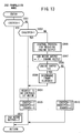
- the second propulsion mode i.e., the EV mode with at least one engine cylinder disabled, or the processing sequence corresponding to the step S309 (see FIG. 10), will be described below with reference to FIG. 13.
- step S501 the main ECU 20 confirms the flag IDSTPEV indicative of the second propulsion mode.
- the flag IDSTPEV has an initial value of "0".
- step S502 If the value of the flag IDSTPEV is "1", i.e., a mode change to the second propulsion mode has been completed, then control goes to step S502. If the value of the flag IDSTPEV is "0", i.e., if the hybrid vehicle 12 is in an initial state or in the middle of changing from a previous mode to the second propulsion mode, then control goes to step S503.
- step S502 the main ECU 20 sets the target drive power F for the output of the second motor 18.
- step S503 the main ECU 20 confirms the flag ENGSTPEV indicative of the first propulsion mode. If the value of the flag ENGSTPEV is "1", i.e., if a previous mode is the first propulsion mode, then control goes to step S504. If the value of the flag ENGSTPEV is "0", i.e., if a previous mode is the engine propulsion mode, then control goes to step S506.
- step S504 the main ECU 20 instructs the front motor ECU 54 to idly rotate the first motor 16.
- step S505 the main ECU 20 sets the flag IDSTPEV to "1" and sets the flags ENGSTPEV, ENGDRV to "0".
- the mode shift to the second propulsion mode is finished by the processing in step S505.
- steps S506 through S509 is the same as the processing in steps S406 through S409. That is, the output of the engine 14 is gradually reduced to substantially zero and the output of the second motor 18 is gradually increased in steps S506 through S509.
- step S510 the main ECU 20 sets the flags ENGSTPEV, IDSTPEV, and ENGDRV to "0".
- the mode change to the second propulsion mode is continued by the processing in step S510.
- step S502 After the processing in step S502, step S505, and step S510, the present cycle of the processing sequence shown in FIG. 13 is put to an end.
- the engine propulsion mode i.e., the processing sequence corresponding to the step S310 (see FIG. 10), will be described below with reference to FIG. 14.
- step S601 the main ECU 20 confirms the flag ENGDRV indicative of the engine propulsion mode.
- the flag ENGDRV has an initial value of "0".
- step S602 i.e., if a mode change to the engine propulsion mode has been completed, the main ECU 20 sets the flag ENGDRV to "1" and sets the flags IDSTPEV, ENGSTPEV to "0".
- step S603 the main ECU 20 confirms the flag ENGSTPEV indicative of the first propulsion mode. If the value of the flag ENGSTPEV is "1", i.e., if the previous mode is the first propulsion mode, then control goes to step S604. If the value of the flag ENGSTPEV is "0", i.e., if the previous mode is the engine propulsion mode, then control goes to step S605.
- step S604 the main ECU 20 controls the front motor ECU 54 to energize the first motor 16 to rotate the crankshaft of the engine 14, and controls the fuel injection ECU 62 to inject fuel and ignite the fuel with the ignition plugs 90, thus starting the engine 14.
- the processing in step S604 is performed when the first propulsion mode changes directly to the engine propulsion mode bypassing the second propulsion mode, which occurs when the hybrid vehicle 12 is quickly accelerated.
- the first motor 16 needs a relatively large amount of electric power Pf2 (see FIG. 5B) because the first motor 16 operates as a starter of the engine 14 and undergoes a large load including a resistance to intake air and exhaust emission. Since the first threshold M1 indicative of the first propulsion mode is established relative to the electric power Pf2, the engine 14 can reliably be started within the performance of the battery 15.
- the front clutch 38a is disengaged, and the engine 14 can easily be started as it is under no load.
- step S605 the main ECU 20 controls the fuel injection ECU 62 to inject fuel and ignite the fuel with the ignition plugs 90, thus starting the engine 14. At this time, since the engine 14 has already been rotating at an idling speed due to the process of the second propulsion mode, there is almost no increase in the current supplied to the first motor 16.
- the main ECU 20 confirms a startup of the engine 14 in step S606. If the engine 14 has not been started, then the main ECU 20 waits until the engine 14 has been started.
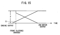
- step S607 the main ECU 20 controls the first front clutch solenoid 104 to engage the front clutch 38a on the input end of the belt-and-pulley mechanism 36. Therefore a small mechanical load is put on the engine 14 from the belt-and-pulley mechanism 36.
- step S608 the main ECU 20 performs a control process for increasing the output of the engine 14.
- the output of the engine 14 is set as an output value produced by adding a predetermined infinitesimal value to a previous output value.
- step S609 the main ECU 20 compares the output of the engine 14 at the time with a threshold T1 that serves as a reference for engaging the front clutch 38b. If the output of the engine 14 is smaller than the threshold T1, then the present cycle of the processing sequence shown in FIG. 14 is put to an end. If the output of the engine 14 is equal to or greater than the threshold T1, then control goes to step S610.
- step S610 the main ECU 20 controls the second front clutch solenoid 106 to engage the front clutch 38b on the output end of the belt-and-pulley mechanism 36, transmitting the drive power from the engine 14 to the front wheels 26a.
- the engine 14 is rotating at a rotational speed that is substantially equal to the threshold T1, it has a inertia of rotational energy, therefore its rotational speed will not abruptly change even when some kind of impact from the road is imposed on the hybrid vehicle.
- step S611 the main ECU 20 calculates the output of the second motor 18, and supplies the calculated output to the rear motor ECU 56.
- the output of the second motor 18 is calculated as a value produced by subtracting the output of the engine 14 from the target drive power F.
- step S612 the main ECU 20 confirms the output value of the second motor 18. If the output value of the second motor 18 is substantially "0", then control goes to step S613. Otherwise, control goes to step S614.
- step S613 the main ECU 20 disengages the rear clutch 46. Then, control goes to step S602.
- step S614 i.e., when a mode change is being made from the second propulsion mode to the engine propulsion mode, the main ECU 20 sets the flags ENGSTPEV, IDSTPEV, and ENGDRV to "0".
- the mode change from the first propulsion mode or the second propulsion mode to the engine propulsion mode can be made while the output of the engine 14 is gradually increased from substantially zero to the target drive power F.
- the rotational speed of the engine 14 is substantially equal to the threshold T1. Therefore, the engine 14 has an inertia of rotational energy, and its rotational speed will not abruptly change even when some kind of impact from the road is imposed on the hybrid vehicle.
- a timer may be used so that the mode change is compulsorily completed after a predetermined time of the timer lapses.
- the crankshaft of the engine 14 has been rotating at the idling speed by the first motor 16 when the second propulsion mode changes to the engine propulsion mode in response to a demand such as an acceleration demand. Consequently, there is almost no increase in the current consumed when the engine 14 starts to operate. In the EV mode, therefore, almost all electric power supplied from the battery 15 is used to energize the second motor 18, increasing the range in which the EV mode can perform, thus reducing consumption of the electric power stored in the battery 15, and reducing fuel consumption.
- the first propulsion mode may change directly to the engine propulsion mode bypassing the second propulsion mode.
- the engine 14 can reliably be started as the electric power Pf2 (see FIG. 5B) for starting the engine 4 is acquired.
- the power consumption of the battery 15 is further reduced.
- the first motor 16 that is supplied with the electric power from the high-voltage battery 15 is used. Accordingly, no conventional starter is required to start the engine 14. As the low-voltage battery 51b is not used to start the engine 14, the voltage of the 12-V power supply system does not drop. Therefore, the controllers such as the main ECU 20 are not adversely affected when the engine 14 is started.
- the drive control apparatus 10 Since the low-voltage battery 51b is charged by the battery 15 through the downverter 51a, no conventional alternator is required. As no starter and no alternator are necessary, the drive control apparatus 10 is relatively simple, lightweight, and inexpensive.
- the modes are switched according to the first threshold M1 and the second threshold M2 based on the maximum electric power Pr that can be supplied to the second motor 18.
- the modes may be switched based on the acceleration ⁇ achievable by the hybrid vehicle 12 with respect to the vehicle speed V.
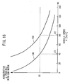
- the relationship between different values of the vehicle speed V and different values of the acceleration ⁇ possible with the second motor 18 is represented by a map having a first acceleration curve 130 indicative of values of the acceleration ⁇ possible with the first propulsion mode, and a second acceleration curve 132 indicative of values of the acceleration ⁇ that can be achieved in the second propulsion mode.
- the first acceleration curve 130 represents an ability of the second motor 18 to accelerate the hybrid vehicle 12 based on the electric power Pr that is produced by subtracting the electric power Pf2 capable of starting the engine 14 from the electric power Pb (see FIG. 5B) of the battery 15 with respect to the SOC.
- the second acceleration curve 132 represents an ability of the second motor 18 to accelerate the hybrid vehicle 12 based on the electric power Pr that is produced by subtracting the electric power Pf1 (see FIG. 5A) capable of idly rotating the first motor 16 from the electric power Pb of the battery 15 with respect to the SOC.
- an acceleration G1 (e.g., 0.5 [m/s 2 ]) at which the hybrid vehicle 12 can be propelled without making the occupants uncomfortable is established on the map, and vehicle speeds V which correspond to the points where the acceleration G1 crosses the first acceleration curve 130 and the second acceleration curve 132 are determined.
- the vehicle speeds V thus determined serve as a first speed threshold V1 and a second speed threshold V2.
- the first speed threshold V1 is 40 [km/h]
- the second speed threshold V2 is 80 [km/h].
- the main ECU 20 performs a processing sequence shown in FIG. 17.
- the processing sequence shown in FIG. 17 corresponds to the processing in step S3 shown in FIG. 7 for determining an EV range in the above embodiment.
- step S701 the main ECU 20 reads values such as the vehicle speed V.
- step S702 the main ECU 20 makes a cruise control decision, i.e., determines whether the hybrid vehicle 12 is cruising (or running stably) or not. The decision is based on whether the changes in the vehicle speed V, the acceleration ⁇ , and the accelerator pedal displacement AP fall in predetermined ranges or not. These parameters may be smoothed by a moving average, if necessary, to determine whether the hybrid vehicle 12 is cruising or not. If the hybrid vehicle 12 is cruising, then control goes to step S703. If the hybrid vehicle 12 is not cruising, then control goes to step S707.
- step S703 the main ECU 20 compares the vehicle speed V with the first speed threshold V1. If the vehicle speed V is smaller than the first speed threshold V1, then control goes to step S705. If the vehicle speed V is equal to or greater than the first speed threshold V1, then control goes to step S704.
- step S704 the main ECU 20 compares the vehicle speed V with the second speed threshold V2. If the vehicle speed V is smaller than the second speed threshold V2, then control goes to step S706. If the vehicle speed V is equal to or greater than the second speed threshold V2, then control goes to step S707.
- step S705 i.e., when the first propulsion mode is to be performed, the main ECU 20 sets the flag RESEV indicating the first propulsion mode to "1", and sets the flag RISEV indicating the second propulsion mode to "0".
- step S706 i.e., when the second propulsion mode is to be performed, the main ECU 20 sets the flag RESEV to "0", and sets the flag RISEV to "1".
- step S707 i.e., when the engine propulsion mode is to be performed, the main ECU 20 sets the flags RESEV, RISEV to "0".
- step S705 After step S705, S706, or S707, the processing sequence shown in FIG. 17 is put to an end.
- the modes can smoothly be switched without decelerating.
- step S703, S704 mode switching is determined based on the vehicle speed V.
- mode switching may be determined based on the rotational speed of the second motor 18, rather than the vehicle speed V. According to such a modification, appropriate mode switching can be accomplished without being affected by the vehicle speed V even if the ratio of gears coupled to the second mode 18 is changed. That is, this modification is applicable to a situation where the speed reduction ratio of the two-speed-switching gear mechanism 51 is changed by the rear clutch 46a shown in FIG. 2.
- only the rear wheels 26b are driven in the first propulsion mode and the second propulsion mode, and only the front wheels 26a are driven in the engine propulsion mode.
- all the four wheels may be driven depending on the conditions in which the hybrid vehicle 12 runs, e.g., when the hybrid vehicle 12 runs on snowy terrain.
- a rotational shaft (28) receives drive power from an engine (14) and a first motor (16), and drives front wheels (26a) through front clutches (38a, 38b).
- a second motor (18) drives rear wheels (26b).
- the first motor (16) and the second motor (18) are supplied with electric power from a battery (15).
- a main ECU (20) controls an electric vehicle mode in which the first clutches (38a, 38b) are disengaged, the supply of fuel to the engine (14) is stopped, and the second motor (18) drives the rear wheels (26b) to propel a hybrid vehicle, by dividing the electric vehicle mode into a first propulsion mode and a second propulsion mode.
- the first propulsion mode the first motor (16) is de-energized.
- a load imposed on the second motor (18) is greater than that of the first propulsion mode, and the first motor (16) is supplied with electric power to rotate the rotational shaft (28) at a predetermined speed.
Landscapes
- Engineering & Computer Science (AREA)
- Chemical & Material Sciences (AREA)
- Combustion & Propulsion (AREA)
- Transportation (AREA)
- Mechanical Engineering (AREA)
- Automation & Control Theory (AREA)
- Electric Propulsion And Braking For Vehicles (AREA)
- Arrangement And Driving Of Transmission Devices (AREA)
- Hybrid Electric Vehicles (AREA)
- Output Control And Ontrol Of Special Type Engine (AREA)
- Control Of Vehicle Engines Or Engines For Specific Uses (AREA)
- Electrical Control Of Air Or Fuel Supplied To Internal-Combustion Engine (AREA)
Applications Claiming Priority (2)
| Application Number | Priority Date | Filing Date | Title |
|---|---|---|---|
| JP2002377864A JP3817516B2 (ja) | 2002-12-26 | 2002-12-26 | ハイブリッド車両の駆動制御装置 |
| JP2002377864 | 2002-12-26 |
Publications (2)
| Publication Number | Publication Date |
|---|---|
| EP1433641A1 true EP1433641A1 (fr) | 2004-06-30 |
| EP1433641B1 EP1433641B1 (fr) | 2006-03-01 |
Family
ID=32463594
Family Applications (1)
| Application Number | Title | Priority Date | Filing Date |
|---|---|---|---|
| EP03029614A Expired - Lifetime EP1433641B1 (fr) | 2002-12-26 | 2003-12-22 | Appareil de commande de transmission pour véhicule hybride |
Country Status (4)
| Country | Link |
|---|---|
| US (1) | US7040433B2 (fr) |
| EP (1) | EP1433641B1 (fr) |
| JP (1) | JP3817516B2 (fr) |
| DE (1) | DE60303731T2 (fr) |
Cited By (49)
| Publication number | Priority date | Publication date | Assignee | Title |
|---|---|---|---|---|
| EP1652712A2 (fr) | 2004-10-29 | 2006-05-03 | Tai-Her Yang | Système d'entraînement à division de puissance en série ou en parallèle à double source |
| WO2006103501A3 (fr) * | 2005-02-23 | 2006-11-23 | Toyota Motor Co Ltd | Dispositif de production d'energie, procede de commande dudit dispositif et vehicule ainsi equipe |
| EP1632378A3 (fr) * | 2004-09-03 | 2006-12-20 | Honda Motor Co., Ltd. | Dispositif de commande pour véhicule hybride |
| FR2927849A1 (fr) * | 2008-02-26 | 2009-08-28 | Peugeot Citroen Automobiles Sa | Procede de couplage d'une machine electrique de traction sur un vehicule hybride et vehicule hybride pour la mise en oeuvre du procede |
| FR2939750A1 (fr) * | 2008-12-16 | 2010-06-18 | Peugeot Citroen Automobiles Sa | Module et systeme de controle et/ou de commande de plusieurs fonctions electroniquement pilotees par plusieurs modules dans un vehicule automobile |
| WO2012016662A1 (fr) * | 2010-08-04 | 2012-02-09 | Mattias Vesterlund | Véhicule automobile et procédé pour actionner un véhicule automobile |
| EP2505409A1 (fr) * | 2011-04-01 | 2012-10-03 | Green Propulsion S.A. | Groupe motopropulseur pour véhicule hybride. |
| US8336653B2 (en) | 2008-08-28 | 2012-12-25 | Byd Co. Ltd. | Hybrid power drive system and drive method |
| WO2013131724A1 (fr) * | 2012-03-09 | 2013-09-12 | Schaeffler Technologies AG & Co. KG | Entraînement hybride d'essieu |
| EP2674644A1 (fr) * | 2006-03-14 | 2013-12-18 | Fallbrook Intellectual Property Company LLC | Selecteur de vitesse de scooter |
| EP2519416A4 (fr) * | 2009-12-31 | 2014-05-07 | Byd Co Ltd | Système d'entraînement hybride et son procédé d'entraînement |
| US9611921B2 (en) | 2012-01-23 | 2017-04-04 | Fallbrook Intellectual Property Company Llc | Infinitely variable transmissions, continuously variable transmissions, methods, assemblies, subassemblies, and components therefor |
| US9618100B2 (en) | 2008-05-07 | 2017-04-11 | Fallbrook Intellectual Property Company Llc | Assemblies and methods for clamping force generation |
| US9677650B2 (en) | 2013-04-19 | 2017-06-13 | Fallbrook Intellectual Property Company Llc | Continuously variable transmission |
| US9676391B2 (en) | 2007-02-01 | 2017-06-13 | Fallbrook Intellectual Property Company Llc | Systems and methods for control of transmission and/or prime mover |
| US9683640B2 (en) | 2008-06-06 | 2017-06-20 | Fallbrook Intellectual Property Company Llc | Infinitely variable transmissions, continuously variable transmissions, methods, assemblies, subassemblies, and components therefor |
| US9683638B2 (en) | 2005-12-30 | 2017-06-20 | Fallbrook Intellectual Property Company Llc | Continuously variable gear transmission |
| US9709138B2 (en) | 2005-11-22 | 2017-07-18 | Fallbrook Intellectual Property Company Llc | Continuously variable transmission |
| US9726282B2 (en) | 2006-06-26 | 2017-08-08 | Fallbrook Intellectual Property Company Llc | Continuously variable transmission |
| US9732848B2 (en) | 2003-02-28 | 2017-08-15 | Fallbrook Intellectual Property Company Llc | Continuously variable transmission |
| US9739375B2 (en) | 2007-12-21 | 2017-08-22 | Fallbrook Intellectual Property Company Llc | Automatic transmissions and methods therefor |
| US9850993B2 (en) | 2008-02-29 | 2017-12-26 | Fallbrook Intellectual Property Company Llc | Continuously and/or infinitely variable transmissions and methods therefor |
| US9869388B2 (en) | 2007-07-05 | 2018-01-16 | Fallbrook Intellectual Property Company Llc | Continuously variable transmission |
| US9878717B2 (en) | 2008-08-05 | 2018-01-30 | Fallbrook Intellectual Property Company Llc | Systems and methods for control of transmission and/or prime mover |
| US9903450B2 (en) | 2008-08-26 | 2018-02-27 | Fallbrook Intellectual Property Company Llc | Continuously variable transmission |
| US9920823B2 (en) | 2009-04-16 | 2018-03-20 | Fallbrook Intellectual Property Company Llc | Continuously variable transmission |
| US9945456B2 (en) | 2007-06-11 | 2018-04-17 | Fallbrook Intellectual Property Company Llc | Continuously variable transmission |
| US9950608B2 (en) | 2005-10-28 | 2018-04-24 | Fallbrook Intellectual Property Company Llc | Electromotive drives |
| US10036453B2 (en) | 2004-10-05 | 2018-07-31 | Fallbrook Intellectual Property Company Llc | Continuously variable transmission |
| US10047861B2 (en) | 2016-01-15 | 2018-08-14 | Fallbrook Intellectual Property Company Llc | Systems and methods for controlling rollback in continuously variable transmissions |
| US10056811B2 (en) | 2007-04-24 | 2018-08-21 | Fallbrook Intellectual Property Company Llc | Electric traction drives |
| US10066712B2 (en) | 2010-03-03 | 2018-09-04 | Fallbrook Intellectual Property Company Llc | Infinitely variable transmissions, continuously variable transmissions, methods, assemblies, subassemblies, and components therefor |
| US10066713B2 (en) | 2008-06-23 | 2018-09-04 | Fallbrook Intellectual Property Company Llc | Continuously variable transmission |
| FR3064575A1 (fr) * | 2017-03-31 | 2018-10-05 | Peugeot Citroen Automobiles Sa | Dispositif de controle des couplages/decouplages d'une machine motrice non-thermique d'un vehicule en fonction d'un parametre d'etat de moyens de stockage associes |
| US10094453B2 (en) | 2007-02-16 | 2018-10-09 | Fallbrook Intellectual Property Company Llc | Infinitely variable transmissions, continuously variable transmissions, methods, assemblies, subassemblies, and components therefor |
| US10100927B2 (en) | 2007-11-16 | 2018-10-16 | Fallbrook Intellectual Property Company Llc | Controller for variable transmission |
| RU2670185C1 (ru) * | 2017-11-23 | 2018-10-18 | Федеральное государственное бюджетное образовательное учреждение высшего образования "Московский автомобильно-дорожный государственный технический университет (МАДИ)" | Комбинированный привод гибридного транспортного средства |
| WO2018206872A1 (fr) * | 2017-05-11 | 2018-11-15 | Psa Automobiles Sa | Dispositif et procédé de contrôle de l'allocation de la puissance de moyens de stockage d'énergie d'un véhicule |
| US10197147B2 (en) | 2010-11-10 | 2019-02-05 | Fallbrook Intellectual Property Company Llc | Continuously variable transmission |
| US10208840B2 (en) | 2005-12-09 | 2019-02-19 | Fallbrook Intellectual Property Company Llc | Continuously variable transmission |
| US10253880B2 (en) | 2008-10-14 | 2019-04-09 | Fallbrook Intellectual Property Company Llc | Continuously variable transmission |
| US10260607B2 (en) | 2007-02-12 | 2019-04-16 | Fallbrook Intellectual Property Company Llc | Continuously variable transmissions and methods therefor |
| US10458526B2 (en) | 2016-03-18 | 2019-10-29 | Fallbrook Intellectual Property Company Llc | Continuously variable transmissions, systems and methods |
| US20200398658A1 (en) * | 2018-02-09 | 2020-12-24 | Zhejiang Geely Holding Group Co., Ltd | Hybrid power drive system and vehicle |
| WO2021214168A1 (fr) * | 2020-04-21 | 2021-10-28 | Jaguar Land Rover Limited | Système et procédé de commande d'une machine électrique pour un véhicule |
| US11174922B2 (en) | 2019-02-26 | 2021-11-16 | Fallbrook Intellectual Property Company Llc | Reversible variable drives and systems and methods for control in forward and reverse directions |
| US11215268B2 (en) | 2018-11-06 | 2022-01-04 | Fallbrook Intellectual Property Company Llc | Continuously variable transmissions, synchronous shifting, twin countershafts and methods for control of same |
| US20220063594A1 (en) * | 2019-01-18 | 2022-03-03 | Mitsubishi Jidosha Kogyo Kabushiki Kaisha | Controller for vehicle |
| US11667351B2 (en) | 2016-05-11 | 2023-06-06 | Fallbrook Intellectual Property Company Llc | Systems and methods for automatic configuration and automatic calibration of continuously variable transmissions and bicycles having continuously variable transmission |
Families Citing this family (74)
| Publication number | Priority date | Publication date | Assignee | Title |
|---|---|---|---|---|
| JP3815401B2 (ja) * | 2002-08-09 | 2006-08-30 | アイシン・エィ・ダブリュ株式会社 | ハイブリッド車用の制御装置 |
| US6979968B2 (en) * | 2003-10-01 | 2005-12-27 | General Motors Corporation | Method and system for managing processor execution time utilizing variable frequency switching |
| JP3701662B2 (ja) * | 2004-02-18 | 2005-10-05 | 本田技研工業株式会社 | ハイブリッド車両の自動変速機制御装置 |
| DE102004032173B4 (de) * | 2004-07-02 | 2015-07-30 | Volkswagen Ag | Verfahren zum Betreiben eines Hybrid-Kraftfahrzeuges |
| US7559387B2 (en) * | 2004-12-20 | 2009-07-14 | Gm Global Technology Operations, Inc. | Deceleration rate based engine spin control and engine off functionality |
| DE102005001047B4 (de) * | 2005-01-07 | 2018-08-16 | Volkswagen Ag | Verfahren zum Betrieb eines Hybridfahrzeugs sowie Hybridfahrzeug |
| JP4876429B2 (ja) * | 2005-04-13 | 2012-02-15 | 日産自動車株式会社 | 車両用駆動制御装置 |
| JP2007064209A (ja) * | 2005-08-05 | 2007-03-15 | Fujitsu Ten Ltd | エンジン制御装置、制御方法、及び制御システム |
| JP2007040279A (ja) * | 2005-08-05 | 2007-02-15 | Toyota Motor Corp | 内燃機関の制御装置 |
| JP4325615B2 (ja) | 2005-12-12 | 2009-09-02 | 日産自動車株式会社 | ハイブリッド車両のエンジン停止制御装置 |
| JP4225314B2 (ja) * | 2005-12-26 | 2009-02-18 | トヨタ自動車株式会社 | ハイブリッド車両 |
| US7882762B2 (en) | 2006-01-30 | 2011-02-08 | Fallbrook Technologies Inc. | System for manipulating a continuously variable transmission |
| JP4680124B2 (ja) | 2006-04-28 | 2011-05-11 | 本田技研工業株式会社 | ハイブリッド車両の駆動制御装置 |
| JP2007296958A (ja) * | 2006-04-28 | 2007-11-15 | Toyota Motor Corp | 車両の制御装置 |
| US20070261902A1 (en) * | 2006-05-15 | 2007-11-15 | George Margoudakis | Electric motor vehicle |
| EP2089642B1 (fr) | 2006-11-08 | 2013-04-10 | Fallbrook Intellectual Property Company LLC | Générateur de force de fixation par serrage |
| US7468562B1 (en) * | 2006-12-25 | 2008-12-23 | Mato Barbic | Intermittant electrical charging AC/DC driving system |
| JP4997986B2 (ja) | 2007-01-19 | 2012-08-15 | トヨタ自動車株式会社 | ハイブリッド車両の制御装置 |
| JP4760756B2 (ja) * | 2007-03-30 | 2011-08-31 | 日産自動車株式会社 | 車両用回生制動装置 |
| JP4760757B2 (ja) * | 2007-03-30 | 2011-08-31 | 日産自動車株式会社 | 車両用駆動装置 |
| JP4727636B2 (ja) * | 2007-09-13 | 2011-07-20 | トヨタ自動車株式会社 | 車両の充電制御装置および車両 |
| US7999180B2 (en) * | 2007-11-30 | 2011-08-16 | Caterpillar Inc. | High voltage wiring system for electric powertrains |
| JP5216953B2 (ja) * | 2008-03-24 | 2013-06-19 | 幸信 森 | 車両用ハイブリッドシステム |
| DE102008029287B4 (de) * | 2008-06-11 | 2010-07-29 | Getrag Innovations Gmbh | Antriebsstrang für ein Kraftfahrzeug |
| DE102008041985A1 (de) * | 2008-09-11 | 2010-03-18 | Robert Bosch Gmbh | Hybridantriebssystem |
| JP5474326B2 (ja) * | 2008-09-29 | 2014-04-16 | 三洋電機株式会社 | 電源装置及び電動車輌 |
| JP2010116896A (ja) * | 2008-11-14 | 2010-05-27 | Mitsubishi Electric Corp | 内燃機関の制御装置 |
| US9162558B2 (en) * | 2009-06-15 | 2015-10-20 | Polaris Industries Inc. | Electric vehicle |
| JP5109101B2 (ja) * | 2009-09-17 | 2012-12-26 | 日立オートモティブシステムズ株式会社 | 車両制御装置 |
| JP2011085078A (ja) * | 2009-10-16 | 2011-04-28 | Hitachi Automotive Systems Ltd | 内燃機関の制御装置及び内燃機関の制御システム |
| DE102010038010A1 (de) * | 2010-10-06 | 2012-04-12 | Dr. Ing. H.C. F. Porsche Aktiengesellschaft | Betriebsverfahren für ein Hybridfahrzeug |
| CN103201153B (zh) | 2010-11-04 | 2016-01-20 | 丰田自动车株式会社 | 混合动力车辆的控制装置 |
| JP5767238B2 (ja) | 2010-11-04 | 2015-08-19 | トヨタ自動車株式会社 | 車両用ハイブリッド駆動装置 |
| CN103189258B (zh) | 2010-11-04 | 2016-05-11 | 丰田自动车株式会社 | 车辆用混合动力驱动装置 |
| DE102010061479B4 (de) | 2010-12-22 | 2025-12-31 | Dr. Ing. H.C. F. Porsche Aktiengesellschaft | Antriebsverfahren und Antriebsvorrichtung für ein Hybridfahrzeug |
| JP2012165564A (ja) * | 2011-02-07 | 2012-08-30 | Toyota Motor Corp | 車両の異常診断装置および車両の異常診断方法 |
| WO2012127674A1 (fr) * | 2011-03-24 | 2012-09-27 | トヨタ自動車株式会社 | Dispositif de commande pour véhicule hybride |
| WO2012138610A1 (fr) | 2011-04-04 | 2012-10-11 | Fallbrook Intellectual Property Company Llc | Groupe auxiliaire de puissance doté d'une transmission à variation continue |
| JP5902417B2 (ja) * | 2011-08-22 | 2016-04-13 | Gknドライブラインジャパン株式会社 | 車両駆動システム |
| JP5682515B2 (ja) * | 2011-09-08 | 2015-03-11 | 三菱自動車工業株式会社 | ハイブリッド電気自動車の制御装置 |
| US8467926B2 (en) * | 2011-11-03 | 2013-06-18 | Ford Global Technologies, Llc | Method and system for valve operation control |
| US8467927B2 (en) * | 2011-11-03 | 2013-06-18 | Ford Global Technologies, Llc | Method and system for speed control of a hybrid vehicle |
| JP5846219B2 (ja) * | 2011-12-19 | 2016-01-20 | トヨタ自動車株式会社 | ハイブリッド車両の駆動制御装置 |
| KR101519807B1 (ko) | 2012-03-26 | 2015-05-12 | 도요타지도샤가부시키가이샤 | 차량의 제어 장치 |
| GB2508670A (en) * | 2012-12-10 | 2014-06-11 | Jaguar Land Rover Ltd | Hybrid vehicle and boost control for gradients |
| US9045136B2 (en) | 2013-02-08 | 2015-06-02 | Efficient Drivetrains, Inc. | Systems and methods for implementing dynamic operating modes and control policies for hybrid electric vehicles |
| US10384527B2 (en) * | 2013-02-08 | 2019-08-20 | Cummins Electrified Power Na Inc. | Four wheel drive powertrain configurations for two-motor, two-clutch hybrid electric vehicles |
| US9421856B2 (en) | 2013-02-08 | 2016-08-23 | Efficient Drivetrains Inc. | Powertrain configurations for two-motor, two-clutch hybrid electric vehicles |
| US10836375B2 (en) | 2013-02-08 | 2020-11-17 | Cummins Electrified Power Na Inc. | Powertrain configurations for single-motor, two-clutch hybrid electric vehicles |
| US20150031501A1 (en) * | 2013-07-24 | 2015-01-29 | GM Global Technology Operations LLC | Hybrid-electric vehicle with continuously variable transmission |
| JP6260173B2 (ja) * | 2013-09-27 | 2018-01-17 | トヨタ自動車株式会社 | 車両の制御装置 |
| US9193273B1 (en) | 2014-06-15 | 2015-11-24 | Efficient Drivetrains, Inc. | Vehicle with AC-to-DC inverter system for vehicle-to-grid power integration |
| CN104842996B (zh) * | 2014-06-18 | 2017-10-10 | 北汽福田汽车股份有限公司 | 一种混合动力汽车换挡方法及系统 |
| CN106604841A (zh) * | 2014-08-22 | 2017-04-26 | 博格华纳公司 | 用于通过道路型混合动力车辆的多模式离合器 |
| KR101637692B1 (ko) | 2014-10-13 | 2016-07-07 | 현대자동차주식회사 | 하이브리드의 변속기 구조 |
| JP2016208777A (ja) * | 2015-04-28 | 2016-12-08 | トヨタ自動車株式会社 | 車両の制御装置 |
| KR101846810B1 (ko) | 2015-07-07 | 2018-04-06 | 닛산 지도우샤 가부시키가이샤 | 하이브리드 차량의 구동력 제어 장치 |
| EP3368360B1 (fr) | 2015-10-27 | 2023-06-07 | The Regents of The University of Michigan | Système hybride à toutes roues motrices à embrayages dynamiques |
| US10377221B2 (en) | 2015-11-12 | 2019-08-13 | GM Global Technology Operations LLC | Powertrain including modular drive unit |
| US9914449B2 (en) * | 2016-01-13 | 2018-03-13 | Ford Global Technologies, Llc | Methods and system for improving efficiency of a hybrid vehicle |
| JP6665582B2 (ja) * | 2016-03-01 | 2020-03-13 | トヨタ自動車株式会社 | ハイブリッド車両 |
| GB2548108B (en) * | 2016-03-07 | 2018-07-18 | Ford Global Tech Llc | Method of controlling a vehicle |
| JP6118932B1 (ja) * | 2016-03-30 | 2017-04-19 | 本田技研工業株式会社 | 駆動装置 |
| JP6643184B2 (ja) * | 2016-05-20 | 2020-02-12 | 本田技研工業株式会社 | 車両 |
| US10118477B2 (en) | 2016-06-14 | 2018-11-06 | Polaris Industries Inc. | Hybrid utility vehicle |
| EP3540127A4 (fr) * | 2016-10-20 | 2020-11-04 | Volvo Construction Equipment AB | Système de commande de déplacement de machine de construction |
| DE102017101744B4 (de) | 2017-01-30 | 2019-06-19 | Gkn Automotive Ltd. | Antriebsanordnung für ein Kraftfahrzeug |
| JP7356691B2 (ja) * | 2017-06-16 | 2023-10-05 | エスアールエム ユニバーシティ | ハイブリッド車のトランスミッション自動切替用機構 |
| JP7176852B2 (ja) | 2018-03-30 | 2022-11-22 | 本田技研工業株式会社 | 車両電源システム |
| US10780770B2 (en) | 2018-10-05 | 2020-09-22 | Polaris Industries Inc. | Hybrid utility vehicle |
| US11370266B2 (en) | 2019-05-16 | 2022-06-28 | Polaris Industries Inc. | Hybrid utility vehicle |
| KR102750677B1 (ko) * | 2020-04-03 | 2025-01-07 | 현대자동차주식회사 | 전동화 차량의 엔진 클러치 제어 방법 |
| US12485981B2 (en) | 2021-03-24 | 2025-12-02 | Polaris Industries Inc. | Electric recreational vehicle |
| FR3145898A1 (fr) * | 2023-02-21 | 2024-08-23 | Adgero Uk Limited | Dispositif d’hybridation intégré dans un véhicule |
Citations (4)
| Publication number | Priority date | Publication date | Assignee | Title |
|---|---|---|---|---|
| DE10102170A1 (de) * | 2000-01-19 | 2001-08-09 | Toyota Motor Co Ltd | Steuerungssystem für ein Fahrzeug mit Brennstoffzelle |
| EP1221394A1 (fr) * | 1999-08-05 | 2002-07-10 | Honda Giken Kogyo Kabushiki Kaisha | Dispositif de commande de vehicule hybride |
| US20020094908A1 (en) * | 2001-01-16 | 2002-07-18 | Nissan Motor Co., Ltd. | Four-wheel drive hybrid vehicle |
| EP1236604A2 (fr) * | 2001-02-28 | 2002-09-04 | Hitachi, Ltd. | Chaíne motrice pour un véhicule hybride avec commande des soupapes d'admission |
Family Cites Families (24)
| Publication number | Priority date | Publication date | Assignee | Title |
|---|---|---|---|---|
| JP2973797B2 (ja) * | 1993-10-15 | 1999-11-08 | トヨタ自動車株式会社 | ハイブリッド電気自動車 |
| JPH09284911A (ja) * | 1996-04-08 | 1997-10-31 | Toyota Motor Corp | 4輪駆動型ハイブリッド車両の駆動制御装置 |
| JP3861321B2 (ja) * | 1996-05-02 | 2006-12-20 | トヨタ自動車株式会社 | ハイブリッド車 |
| JP3374675B2 (ja) * | 1996-10-25 | 2003-02-10 | トヨタ自動車株式会社 | ハイブリッド車両およびエンジン始動制御方法 |
| JPH11208297A (ja) * | 1998-01-26 | 1999-08-03 | Honda Motor Co Ltd | ハイブリッド車両 |
| JP3927342B2 (ja) * | 1999-10-08 | 2007-06-06 | トヨタ自動車株式会社 | 前後輪駆動車両およびその制御装置 |
| JP3458795B2 (ja) | 1999-10-08 | 2003-10-20 | トヨタ自動車株式会社 | ハイブリッド駆動装置 |
| JP3649058B2 (ja) * | 1999-10-08 | 2005-05-18 | トヨタ自動車株式会社 | 複数の原動機を備えた車両の制御装置 |
| DE60132123T2 (de) * | 2000-03-01 | 2008-04-30 | Hitachi, Ltd. | Elektrisches Generatorsystem für Fahrzeuge und sein Regelverfahren |
| JP3415601B2 (ja) * | 2000-10-23 | 2003-06-09 | 本田技研工業株式会社 | ハイブリッド車両の制御装置 |
| US6971461B2 (en) * | 2000-11-13 | 2005-12-06 | Honda Giken Kogyo Kabushiki Kaisha | Front and rear wheel drive vehicle and control device for controlling same |
| JP3589208B2 (ja) * | 2001-08-13 | 2004-11-17 | 日産自動車株式会社 | ハイブリッド車両の駆動装置 |
| US7270205B2 (en) * | 2002-05-22 | 2007-09-18 | Jtekt Corporation | Vehicle drive device, and front-and-rear wheel-driven vehicle formed of the device |
| JP3610969B2 (ja) * | 2002-08-27 | 2005-01-19 | 日産自動車株式会社 | 四輪駆動車両の駆動力制御装置 |
| JP3610970B2 (ja) * | 2002-08-30 | 2005-01-19 | 日産自動車株式会社 | 四輪駆動車両の駆動力制御装置 |
| JP3687639B2 (ja) * | 2002-09-03 | 2005-08-24 | 日産自動車株式会社 | 電動モータ駆動車輪の回転方向判別装置 |
| JP3573146B2 (ja) * | 2002-09-03 | 2004-10-06 | 日産自動車株式会社 | 車両の駆動制御装置 |
| JP3863838B2 (ja) * | 2002-11-12 | 2006-12-27 | 本田技研工業株式会社 | ハイブリッド車両 |
| US6932738B2 (en) * | 2002-12-26 | 2005-08-23 | Honda Motor Co., Ltd. | Drive control apparatus for hybrid vehicle |
| JP2004222413A (ja) * | 2003-01-15 | 2004-08-05 | Honda Motor Co Ltd | ハイブリッド車両の制御装置 |
| JP2005106266A (ja) * | 2003-09-11 | 2005-04-21 | Honda Motor Co Ltd | 車両用駆動装置 |
| KR100588500B1 (ko) * | 2003-09-24 | 2006-06-13 | 현대자동차주식회사 | 모터를 이용한 사륜구동 장치 및 그 제어방법 |
| JP4146784B2 (ja) * | 2003-11-18 | 2008-09-10 | 富士重工業株式会社 | ハイブリッド車両の駆動力制御装置 |
| JP3701662B2 (ja) * | 2004-02-18 | 2005-10-05 | 本田技研工業株式会社 | ハイブリッド車両の自動変速機制御装置 |
-
2002
- 2002-12-26 JP JP2002377864A patent/JP3817516B2/ja not_active Expired - Fee Related
-
2003
- 2003-12-22 EP EP03029614A patent/EP1433641B1/fr not_active Expired - Lifetime
- 2003-12-22 DE DE60303731T patent/DE60303731T2/de not_active Expired - Lifetime
- 2003-12-24 US US10/744,011 patent/US7040433B2/en not_active Expired - Lifetime
Patent Citations (4)
| Publication number | Priority date | Publication date | Assignee | Title |
|---|---|---|---|---|
| EP1221394A1 (fr) * | 1999-08-05 | 2002-07-10 | Honda Giken Kogyo Kabushiki Kaisha | Dispositif de commande de vehicule hybride |
| DE10102170A1 (de) * | 2000-01-19 | 2001-08-09 | Toyota Motor Co Ltd | Steuerungssystem für ein Fahrzeug mit Brennstoffzelle |
| US20020094908A1 (en) * | 2001-01-16 | 2002-07-18 | Nissan Motor Co., Ltd. | Four-wheel drive hybrid vehicle |
| EP1236604A2 (fr) * | 2001-02-28 | 2002-09-04 | Hitachi, Ltd. | Chaíne motrice pour un véhicule hybride avec commande des soupapes d'admission |
Cited By (81)
| Publication number | Priority date | Publication date | Assignee | Title |
|---|---|---|---|---|
| US10428939B2 (en) | 2003-02-28 | 2019-10-01 | Fallbrook Intellectual Property Company Llc | Continuously variable transmission |
| US9732848B2 (en) | 2003-02-28 | 2017-08-15 | Fallbrook Intellectual Property Company Llc | Continuously variable transmission |
| EP1632378A3 (fr) * | 2004-09-03 | 2006-12-20 | Honda Motor Co., Ltd. | Dispositif de commande pour véhicule hybride |
| US7540344B2 (en) | 2004-09-03 | 2009-06-02 | Honda Motor Co., Ltd. | Control apparatus for hybrid vehicle |
| US10036453B2 (en) | 2004-10-05 | 2018-07-31 | Fallbrook Intellectual Property Company Llc | Continuously variable transmission |
| EP2562022A3 (fr) * | 2004-10-29 | 2013-07-31 | Tai-Her Yang | Système d'entraînement divisé à puissance double hybride en série-parallèle |
| EP1652712A2 (fr) | 2004-10-29 | 2006-05-03 | Tai-Her Yang | Système d'entraînement à division de puissance en série ou en parallèle à double source |
| EP1652712B1 (fr) * | 2004-10-29 | 2012-12-19 | Tai-Her Yang | Système d'entraînement à division de puissance en série ou en parallèle à double source |
| US7962257B2 (en) | 2005-02-23 | 2011-06-14 | Toyota Jidosha Kabushiki Kaisha | Power output device, control method for the same, and vehicle equipped therewith |
| WO2006103501A3 (fr) * | 2005-02-23 | 2006-11-23 | Toyota Motor Co Ltd | Dispositif de production d'energie, procede de commande dudit dispositif et vehicule ainsi equipe |
| US9950608B2 (en) | 2005-10-28 | 2018-04-24 | Fallbrook Intellectual Property Company Llc | Electromotive drives |
| US10711869B2 (en) | 2005-11-22 | 2020-07-14 | Fallbrook Intellectual Property Company Llc | Continuously variable transmission |
| US9709138B2 (en) | 2005-11-22 | 2017-07-18 | Fallbrook Intellectual Property Company Llc | Continuously variable transmission |
| US11454303B2 (en) | 2005-12-09 | 2022-09-27 | Fallbrook Intellectual Property Company Llc | Continuously variable transmission |
| US10208840B2 (en) | 2005-12-09 | 2019-02-19 | Fallbrook Intellectual Property Company Llc | Continuously variable transmission |
| US11598397B2 (en) | 2005-12-30 | 2023-03-07 | Fallbrook Intellectual Property Company Llc | Continuously variable gear transmission |
| US9683638B2 (en) | 2005-12-30 | 2017-06-20 | Fallbrook Intellectual Property Company Llc | Continuously variable gear transmission |
| EP2674644A1 (fr) * | 2006-03-14 | 2013-12-18 | Fallbrook Intellectual Property Company LLC | Selecteur de vitesse de scooter |
| US9726282B2 (en) | 2006-06-26 | 2017-08-08 | Fallbrook Intellectual Property Company Llc | Continuously variable transmission |
| US10703372B2 (en) | 2007-02-01 | 2020-07-07 | Fallbrook Intellectual Property Company Llc | Systems and methods for control of transmission and/or prime mover |
| US9878719B2 (en) | 2007-02-01 | 2018-01-30 | Fallbrook Intellectual Property Company Llc | Systems and methods for control of transmission and/or prime mover |
| US9676391B2 (en) | 2007-02-01 | 2017-06-13 | Fallbrook Intellectual Property Company Llc | Systems and methods for control of transmission and/or prime mover |
| US10260607B2 (en) | 2007-02-12 | 2019-04-16 | Fallbrook Intellectual Property Company Llc | Continuously variable transmissions and methods therefor |
| US10094453B2 (en) | 2007-02-16 | 2018-10-09 | Fallbrook Intellectual Property Company Llc | Infinitely variable transmissions, continuously variable transmissions, methods, assemblies, subassemblies, and components therefor |
| US10056811B2 (en) | 2007-04-24 | 2018-08-21 | Fallbrook Intellectual Property Company Llc | Electric traction drives |
| US9945456B2 (en) | 2007-06-11 | 2018-04-17 | Fallbrook Intellectual Property Company Llc | Continuously variable transmission |
| US9869388B2 (en) | 2007-07-05 | 2018-01-16 | Fallbrook Intellectual Property Company Llc | Continuously variable transmission |
| US10260629B2 (en) | 2007-07-05 | 2019-04-16 | Fallbrook Intellectual Property Company Llc | Continuously variable transmission |
| US11125329B2 (en) | 2007-11-16 | 2021-09-21 | Fallbrook Intellectual Property Company Llc | Controller for variable transmission |
| US10100927B2 (en) | 2007-11-16 | 2018-10-16 | Fallbrook Intellectual Property Company Llc | Controller for variable transmission |
| US9739375B2 (en) | 2007-12-21 | 2017-08-22 | Fallbrook Intellectual Property Company Llc | Automatic transmissions and methods therefor |
| US10704687B2 (en) | 2007-12-21 | 2020-07-07 | Fallbrook Intellectual Property Company Llc | Automatic transmissions and methods therefor |
| FR2927849A1 (fr) * | 2008-02-26 | 2009-08-28 | Peugeot Citroen Automobiles Sa | Procede de couplage d'une machine electrique de traction sur un vehicule hybride et vehicule hybride pour la mise en oeuvre du procede |
| WO2009112750A3 (fr) * | 2008-02-26 | 2009-11-05 | Peugeot Citroën Automobiles SA | Procede de couplage d'une machine electrique de traction sur un vehicule hybride et vehicule hybride pour la mise en oeuvre du procede |
| US9850993B2 (en) | 2008-02-29 | 2017-12-26 | Fallbrook Intellectual Property Company Llc | Continuously and/or infinitely variable transmissions and methods therefor |
| US9618100B2 (en) | 2008-05-07 | 2017-04-11 | Fallbrook Intellectual Property Company Llc | Assemblies and methods for clamping force generation |
| US9683640B2 (en) | 2008-06-06 | 2017-06-20 | Fallbrook Intellectual Property Company Llc | Infinitely variable transmissions, continuously variable transmissions, methods, assemblies, subassemblies, and components therefor |
| US10634224B2 (en) | 2008-06-06 | 2020-04-28 | Fallbrook Intellectual Property Company Llc | Infinitely variable transmissions, continuously variable transmissions, methods, assemblies, subassemblies, and components therefor |
| US10066713B2 (en) | 2008-06-23 | 2018-09-04 | Fallbrook Intellectual Property Company Llc | Continuously variable transmission |
| US9878717B2 (en) | 2008-08-05 | 2018-01-30 | Fallbrook Intellectual Property Company Llc | Systems and methods for control of transmission and/or prime mover |
| US10704657B2 (en) | 2008-08-26 | 2020-07-07 | Fallbrook Intellectual Property Company Llc | Continuously variable transmission |
| US9903450B2 (en) | 2008-08-26 | 2018-02-27 | Fallbrook Intellectual Property Company Llc | Continuously variable transmission |
| US8336653B2 (en) | 2008-08-28 | 2012-12-25 | Byd Co. Ltd. | Hybrid power drive system and drive method |
| US10253880B2 (en) | 2008-10-14 | 2019-04-09 | Fallbrook Intellectual Property Company Llc | Continuously variable transmission |
| FR2939750A1 (fr) * | 2008-12-16 | 2010-06-18 | Peugeot Citroen Automobiles Sa | Module et systeme de controle et/ou de commande de plusieurs fonctions electroniquement pilotees par plusieurs modules dans un vehicule automobile |
| US9920823B2 (en) | 2009-04-16 | 2018-03-20 | Fallbrook Intellectual Property Company Llc | Continuously variable transmission |
| US10746270B2 (en) | 2009-04-16 | 2020-08-18 | Fallbrook Intellectual Property Company Llc | Continuously variable transmission |
| EP2519416A4 (fr) * | 2009-12-31 | 2014-05-07 | Byd Co Ltd | Système d'entraînement hybride et son procédé d'entraînement |
| US10066712B2 (en) | 2010-03-03 | 2018-09-04 | Fallbrook Intellectual Property Company Llc | Infinitely variable transmissions, continuously variable transmissions, methods, assemblies, subassemblies, and components therefor |
| WO2012016662A1 (fr) * | 2010-08-04 | 2012-02-09 | Mattias Vesterlund | Véhicule automobile et procédé pour actionner un véhicule automobile |
| US10197147B2 (en) | 2010-11-10 | 2019-02-05 | Fallbrook Intellectual Property Company Llc | Continuously variable transmission |
| EP2505409A1 (fr) * | 2011-04-01 | 2012-10-03 | Green Propulsion S.A. | Groupe motopropulseur pour véhicule hybride. |
| US9611921B2 (en) | 2012-01-23 | 2017-04-04 | Fallbrook Intellectual Property Company Llc | Infinitely variable transmissions, continuously variable transmissions, methods, assemblies, subassemblies, and components therefor |
| US10428915B2 (en) | 2012-01-23 | 2019-10-01 | Fallbrook Intellectual Property Company Llc | Infinitely variable transmissions, continuously variable transmissions, methods, assemblies, subassemblies, and components therefor |
| WO2013131724A1 (fr) * | 2012-03-09 | 2013-09-12 | Schaeffler Technologies AG & Co. KG | Entraînement hybride d'essieu |
| US10029554B2 (en) | 2012-03-09 | 2018-07-24 | Schaeffler Technologies AG & Co. KG | Axle hybrid drive |
| US10323732B2 (en) | 2013-04-19 | 2019-06-18 | Fallbrook Intellectual Property Company Llc | Continuously variable transmission |
| US9677650B2 (en) | 2013-04-19 | 2017-06-13 | Fallbrook Intellectual Property Company Llc | Continuously variable transmission |
| US10047861B2 (en) | 2016-01-15 | 2018-08-14 | Fallbrook Intellectual Property Company Llc | Systems and methods for controlling rollback in continuously variable transmissions |
| US11306818B2 (en) | 2016-01-15 | 2022-04-19 | Fallbrook Intellectual Property Company Llc | Systems and methods for controlling rollback in continuously variable transmissions |
| US10920882B2 (en) | 2016-01-15 | 2021-02-16 | Fallbrook Intellectual Property Company Llc | Systems and methods for controlling rollback in continuously variable transmissions |
| US10458526B2 (en) | 2016-03-18 | 2019-10-29 | Fallbrook Intellectual Property Company Llc | Continuously variable transmissions, systems and methods |
| US11667351B2 (en) | 2016-05-11 | 2023-06-06 | Fallbrook Intellectual Property Company Llc | Systems and methods for automatic configuration and automatic calibration of continuously variable transmissions and bicycles having continuously variable transmission |
| US12145690B2 (en) | 2016-05-11 | 2024-11-19 | Enviolo B.V. | Systems and methods for automatic configuration and automatic calibration of continuously variable transmissions and bicycles having continuously variable transmissions |
| FR3064575A1 (fr) * | 2017-03-31 | 2018-10-05 | Peugeot Citroen Automobiles Sa | Dispositif de controle des couplages/decouplages d'une machine motrice non-thermique d'un vehicule en fonction d'un parametre d'etat de moyens de stockage associes |
| CN110612239A (zh) * | 2017-05-11 | 2019-12-24 | 标致雪铁龙汽车股份有限公司 | 用于控制分配车辆的储能装置的功率的设备和方法 |
| WO2018206872A1 (fr) * | 2017-05-11 | 2018-11-15 | Psa Automobiles Sa | Dispositif et procédé de contrôle de l'allocation de la puissance de moyens de stockage d'énergie d'un véhicule |
| FR3066168A1 (fr) * | 2017-05-11 | 2018-11-16 | Peugeot Citroen Automobiles Sa | Dispositif et procede de controle de l'allocation de la puissance de moyens de stockage d'energie d'un vehicule |
| RU2670185C1 (ru) * | 2017-11-23 | 2018-10-18 | Федеральное государственное бюджетное образовательное учреждение высшего образования "Московский автомобильно-дорожный государственный технический университет (МАДИ)" | Комбинированный привод гибридного транспортного средства |
| US20200398658A1 (en) * | 2018-02-09 | 2020-12-24 | Zhejiang Geely Holding Group Co., Ltd | Hybrid power drive system and vehicle |
| US11215268B2 (en) | 2018-11-06 | 2022-01-04 | Fallbrook Intellectual Property Company Llc | Continuously variable transmissions, synchronous shifting, twin countershafts and methods for control of same |
| US11624432B2 (en) | 2018-11-06 | 2023-04-11 | Fallbrook Intellectual Property Company Llc | Continuously variable transmissions, synchronous shifting, twin countershafts and methods for control of same |
| US12173778B2 (en) | 2018-11-06 | 2024-12-24 | Enviolo B.V. | Continuously variable transmissions, synchronous shifting, twin countershafts and methods for control of same |
| US20220063594A1 (en) * | 2019-01-18 | 2022-03-03 | Mitsubishi Jidosha Kogyo Kabushiki Kaisha | Controller for vehicle |
| US11981321B2 (en) * | 2019-01-18 | 2024-05-14 | Mitsubishi Jidosha Kogyo Kabushiki Kaisha | Controller for vehicle |
| US11530739B2 (en) | 2019-02-26 | 2022-12-20 | Fallbrook Intellectual Property Company Llc | Reversible variable drives and systems and methods for control in forward and reverse directions |
| US11174922B2 (en) | 2019-02-26 | 2021-11-16 | Fallbrook Intellectual Property Company Llc | Reversible variable drives and systems and methods for control in forward and reverse directions |
| US12000458B2 (en) | 2019-02-26 | 2024-06-04 | Fallbrook Intellectual Property Company Llc | Reversible variable drives and systems and methods for control in forward and reverse directions |
| US12442434B2 (en) | 2019-02-26 | 2025-10-14 | Enviolo B.V. | Reversible variable drives and systems and methods for control in forward and reverse directions |
| WO2021214168A1 (fr) * | 2020-04-21 | 2021-10-28 | Jaguar Land Rover Limited | Système et procédé de commande d'une machine électrique pour un véhicule |
| US12252110B2 (en) | 2020-04-21 | 2025-03-18 | Jaguar Land Rover Limited | System and method for controlling an electric machine for a vehicle |
Also Published As
| Publication number | Publication date |
|---|---|
| JP2004208477A (ja) | 2004-07-22 |
| US20040134698A1 (en) | 2004-07-15 |
| US7040433B2 (en) | 2006-05-09 |
| DE60303731T2 (de) | 2006-08-10 |
| JP3817516B2 (ja) | 2006-09-06 |
| EP1433641B1 (fr) | 2006-03-01 |
| DE60303731D1 (de) | 2006-04-27 |
Similar Documents
| Publication | Publication Date | Title |
|---|---|---|
| EP1433641B1 (fr) | Appareil de commande de transmission pour véhicule hybride | |
| US6662096B2 (en) | Vehicle drive system and vehicle controlling method | |
| US6932738B2 (en) | Drive control apparatus for hybrid vehicle | |
| US7216729B2 (en) | Method and system of requesting engine on/off state in a hybrid electric vehicle | |
| CA2785019C (fr) | Dispositif de commande pour vehicule hybride | |
| US8050851B2 (en) | Power output apparatus, vehicle equipped with power output apparatus, driving system, and control method of power output apparatus | |
| JP4225314B2 (ja) | ハイブリッド車両 | |
| EP1939059B1 (fr) | Système de contrôle de changement de mode pour véhicule hybride | |
| US8096375B2 (en) | Vehicle and control method thereof | |
| US20090306843A1 (en) | Hybrid vehicle and control method thereof | |
| US20190283730A1 (en) | Control system for hybrid vehicle | |
| US7243011B2 (en) | Hybrid transmission launch algorithm | |
| US10040442B2 (en) | Hybrid vehicle | |
| JP2004222413A (ja) | ハイブリッド車両の制御装置 | |
| JP4240845B2 (ja) | ハイブリッド車 | |
| JP7753931B2 (ja) | 車両の制御装置 | |
| JP2005225282A (ja) | 駆動力切換制御装置 | |
| JP3924540B2 (ja) | ハイブリッド車両の駆動制御装置 | |
| JP3817515B2 (ja) | ハイブリッド車両の駆動制御装置 | |
| JP7694142B2 (ja) | 制御装置 | |
| JP4254764B2 (ja) | 自動車およびその制御方法 | |
| JP5699533B2 (ja) | ハイブリッド車両の制御装置 | |
| JP2003130199A (ja) | 有段変速機を備えたハイブリッド車両 | |
| JP2022117591A (ja) | 車両駆動装置 | |
| KR20200116188A (ko) | 마일드 하이브리드 차량의 mhsg 제어 시스템 및 방법 |
Legal Events
| Date | Code | Title | Description |
|---|---|---|---|
| PUAI | Public reference made under article 153(3) epc to a published international application that has entered the european phase |
Free format text: ORIGINAL CODE: 0009012 |
|
| AK | Designated contracting states |
Kind code of ref document: A1 Designated state(s): AT BE BG CH CY CZ DE DK EE ES FI FR GB GR HU IE IT LI LU MC NL PT RO SE SI SK TR |
|
| AX | Request for extension of the european patent |
Extension state: AL LT LV MK |
|
| 17P | Request for examination filed |
Effective date: 20040629 |
|
| 17Q | First examination report despatched |
Effective date: 20041102 |
|
| AKX | Designation fees paid |
Designated state(s): DE FR GB |
|
| GRAP | Despatch of communication of intention to grant a patent |
Free format text: ORIGINAL CODE: EPIDOSNIGR1 |
|
| GRAS | Grant fee paid |
Free format text: ORIGINAL CODE: EPIDOSNIGR3 |
|
| GRAA | (expected) grant |
Free format text: ORIGINAL CODE: 0009210 |
|
| RIN1 | Information on inventor provided before grant (corrected) |
Inventor name: KUBODERA, MASAO Inventor name: TATARA, YUSUKE Inventor name: KIRA, NOBUHIRO Inventor name: YAMAMOTO, KAZUHISA |
|
| AK | Designated contracting states |
Kind code of ref document: B1 Designated state(s): DE FR GB |
|
| REG | Reference to a national code |
Ref country code: GB Ref legal event code: FG4D |
|
| RIN2 | Information on inventor provided after grant (corrected) |
Inventor name: TATARA, YUSUKE Inventor name: KUBODERA, MASAO Inventor name: KIRA, NOBUHIRO Inventor name: YAMAMOTO, KAZUHISA |
|
| REF | Corresponds to: |
Ref document number: 60303731 Country of ref document: DE Date of ref document: 20060427 Kind code of ref document: P |
|
| ET | Fr: translation filed | ||
| PLBE | No opposition filed within time limit |
Free format text: ORIGINAL CODE: 0009261 |
|
| STAA | Information on the status of an ep patent application or granted ep patent |
Free format text: STATUS: NO OPPOSITION FILED WITHIN TIME LIMIT |
|
| 26N | No opposition filed |
Effective date: 20061204 |
|
| PGFP | Annual fee paid to national office [announced via postgrant information from national office to epo] |
Ref country code: GB Payment date: 20101222 Year of fee payment: 8 |
|
| PGFP | Annual fee paid to national office [announced via postgrant information from national office to epo] |
Ref country code: FR Payment date: 20111219 Year of fee payment: 9 |
|
| GBPC | Gb: european patent ceased through non-payment of renewal fee |
Effective date: 20121222 |
|
| REG | Reference to a national code |
Ref country code: FR Ref legal event code: ST Effective date: 20130830 |
|
| REG | Reference to a national code |
Ref country code: DE Ref legal event code: R084 Ref document number: 60303731 Country of ref document: DE Effective date: 20130802 |
|
| PG25 | Lapsed in a contracting state [announced via postgrant information from national office to epo] |
Ref country code: GB Free format text: LAPSE BECAUSE OF NON-PAYMENT OF DUE FEES Effective date: 20121222 Ref country code: FR Free format text: LAPSE BECAUSE OF NON-PAYMENT OF DUE FEES Effective date: 20130102 |
|
| PGFP | Annual fee paid to national office [announced via postgrant information from national office to epo] |
Ref country code: DE Payment date: 20181211 Year of fee payment: 16 |
|
| REG | Reference to a national code |
Ref country code: DE Ref legal event code: R119 Ref document number: 60303731 Country of ref document: DE |
|
| PG25 | Lapsed in a contracting state [announced via postgrant information from national office to epo] |
Ref country code: DE Free format text: LAPSE BECAUSE OF NON-PAYMENT OF DUE FEES Effective date: 20200701 |