EP1652712B1 - Système d'entraînement à division de puissance en série ou en parallèle à double source - Google Patents
Système d'entraînement à division de puissance en série ou en parallèle à double source Download PDFInfo
- Publication number
- EP1652712B1 EP1652712B1 EP05256643A EP05256643A EP1652712B1 EP 1652712 B1 EP1652712 B1 EP 1652712B1 EP 05256643 A EP05256643 A EP 05256643A EP 05256643 A EP05256643 A EP 05256643A EP 1652712 B1 EP1652712 B1 EP 1652712B1
- Authority
- EP
- European Patent Office
- Prior art keywords
- drive system
- unit
- drive
- dynamo
- clutch
- Prior art date
- Legal status (The legal status is an assumption and is not a legal conclusion. Google has not performed a legal analysis and makes no representation as to the accuracy of the status listed.)
- Expired - Lifetime
Links
Images

















Classifications
-
- B—PERFORMING OPERATIONS; TRANSPORTING
- B60—VEHICLES IN GENERAL
- B60W—CONJOINT CONTROL OF VEHICLE SUB-UNITS OF DIFFERENT TYPE OR DIFFERENT FUNCTION; CONTROL SYSTEMS SPECIALLY ADAPTED FOR HYBRID VEHICLES; ROAD VEHICLE DRIVE CONTROL SYSTEMS FOR PURPOSES NOT RELATED TO THE CONTROL OF A PARTICULAR SUB-UNIT
- B60W20/00—Control systems specially adapted for hybrid vehicles
- B60W20/20—Control strategies involving selection of hybrid configuration, e.g. selection between series or parallel configuration
-
- B—PERFORMING OPERATIONS; TRANSPORTING
- B60—VEHICLES IN GENERAL
- B60K—ARRANGEMENT OR MOUNTING OF PROPULSION UNITS OR OF TRANSMISSIONS IN VEHICLES; ARRANGEMENT OR MOUNTING OF PLURAL DIVERSE PRIME-MOVERS IN VEHICLES; AUXILIARY DRIVES FOR VEHICLES; INSTRUMENTATION OR DASHBOARDS FOR VEHICLES; ARRANGEMENTS IN CONNECTION WITH COOLING, AIR INTAKE, GAS EXHAUST OR FUEL SUPPLY OF PROPULSION UNITS IN VEHICLES
- B60K6/00—Arrangement or mounting of plural diverse prime-movers for mutual or common propulsion, e.g. hybrid propulsion systems comprising electric motors and internal combustion engines
- B60K6/20—Arrangement or mounting of plural diverse prime-movers for mutual or common propulsion, e.g. hybrid propulsion systems comprising electric motors and internal combustion engines the prime-movers consisting of electric motors and internal combustion engines, e.g. HEVs
- B60K6/22—Arrangement or mounting of plural diverse prime-movers for mutual or common propulsion, e.g. hybrid propulsion systems comprising electric motors and internal combustion engines the prime-movers consisting of electric motors and internal combustion engines, e.g. HEVs characterised by apparatus, components or means specially adapted for HEVs
- B60K6/38—Arrangement or mounting of plural diverse prime-movers for mutual or common propulsion, e.g. hybrid propulsion systems comprising electric motors and internal combustion engines the prime-movers consisting of electric motors and internal combustion engines, e.g. HEVs characterised by apparatus, components or means specially adapted for HEVs characterised by the driveline clutches
- B60K6/387—Actuated clutches, i.e. clutches engaged or disengaged by electric, hydraulic or mechanical actuating means
-
- B—PERFORMING OPERATIONS; TRANSPORTING
- B60—VEHICLES IN GENERAL
- B60K—ARRANGEMENT OR MOUNTING OF PROPULSION UNITS OR OF TRANSMISSIONS IN VEHICLES; ARRANGEMENT OR MOUNTING OF PLURAL DIVERSE PRIME-MOVERS IN VEHICLES; AUXILIARY DRIVES FOR VEHICLES; INSTRUMENTATION OR DASHBOARDS FOR VEHICLES; ARRANGEMENTS IN CONNECTION WITH COOLING, AIR INTAKE, GAS EXHAUST OR FUEL SUPPLY OF PROPULSION UNITS IN VEHICLES
- B60K6/00—Arrangement or mounting of plural diverse prime-movers for mutual or common propulsion, e.g. hybrid propulsion systems comprising electric motors and internal combustion engines
- B60K6/20—Arrangement or mounting of plural diverse prime-movers for mutual or common propulsion, e.g. hybrid propulsion systems comprising electric motors and internal combustion engines the prime-movers consisting of electric motors and internal combustion engines, e.g. HEVs
- B60K6/42—Arrangement or mounting of plural diverse prime-movers for mutual or common propulsion, e.g. hybrid propulsion systems comprising electric motors and internal combustion engines the prime-movers consisting of electric motors and internal combustion engines, e.g. HEVs characterised by the architecture of the hybrid electric vehicle
- B60K6/44—Series-parallel type
-
- B—PERFORMING OPERATIONS; TRANSPORTING
- B60—VEHICLES IN GENERAL
- B60K—ARRANGEMENT OR MOUNTING OF PROPULSION UNITS OR OF TRANSMISSIONS IN VEHICLES; ARRANGEMENT OR MOUNTING OF PLURAL DIVERSE PRIME-MOVERS IN VEHICLES; AUXILIARY DRIVES FOR VEHICLES; INSTRUMENTATION OR DASHBOARDS FOR VEHICLES; ARRANGEMENTS IN CONNECTION WITH COOLING, AIR INTAKE, GAS EXHAUST OR FUEL SUPPLY OF PROPULSION UNITS IN VEHICLES
- B60K6/00—Arrangement or mounting of plural diverse prime-movers for mutual or common propulsion, e.g. hybrid propulsion systems comprising electric motors and internal combustion engines
- B60K6/20—Arrangement or mounting of plural diverse prime-movers for mutual or common propulsion, e.g. hybrid propulsion systems comprising electric motors and internal combustion engines the prime-movers consisting of electric motors and internal combustion engines, e.g. HEVs
- B60K6/42—Arrangement or mounting of plural diverse prime-movers for mutual or common propulsion, e.g. hybrid propulsion systems comprising electric motors and internal combustion engines the prime-movers consisting of electric motors and internal combustion engines, e.g. HEVs characterised by the architecture of the hybrid electric vehicle
- B60K6/44—Series-parallel type
- B60K6/442—Series-parallel switching type
-
- B—PERFORMING OPERATIONS; TRANSPORTING
- B60—VEHICLES IN GENERAL
- B60K—ARRANGEMENT OR MOUNTING OF PROPULSION UNITS OR OF TRANSMISSIONS IN VEHICLES; ARRANGEMENT OR MOUNTING OF PLURAL DIVERSE PRIME-MOVERS IN VEHICLES; AUXILIARY DRIVES FOR VEHICLES; INSTRUMENTATION OR DASHBOARDS FOR VEHICLES; ARRANGEMENTS IN CONNECTION WITH COOLING, AIR INTAKE, GAS EXHAUST OR FUEL SUPPLY OF PROPULSION UNITS IN VEHICLES
- B60K6/00—Arrangement or mounting of plural diverse prime-movers for mutual or common propulsion, e.g. hybrid propulsion systems comprising electric motors and internal combustion engines
- B60K6/20—Arrangement or mounting of plural diverse prime-movers for mutual or common propulsion, e.g. hybrid propulsion systems comprising electric motors and internal combustion engines the prime-movers consisting of electric motors and internal combustion engines, e.g. HEVs
- B60K6/42—Arrangement or mounting of plural diverse prime-movers for mutual or common propulsion, e.g. hybrid propulsion systems comprising electric motors and internal combustion engines the prime-movers consisting of electric motors and internal combustion engines, e.g. HEVs characterised by the architecture of the hybrid electric vehicle
- B60K6/46—Series type
-
- B—PERFORMING OPERATIONS; TRANSPORTING
- B60—VEHICLES IN GENERAL
- B60K—ARRANGEMENT OR MOUNTING OF PROPULSION UNITS OR OF TRANSMISSIONS IN VEHICLES; ARRANGEMENT OR MOUNTING OF PLURAL DIVERSE PRIME-MOVERS IN VEHICLES; AUXILIARY DRIVES FOR VEHICLES; INSTRUMENTATION OR DASHBOARDS FOR VEHICLES; ARRANGEMENTS IN CONNECTION WITH COOLING, AIR INTAKE, GAS EXHAUST OR FUEL SUPPLY OF PROPULSION UNITS IN VEHICLES
- B60K6/00—Arrangement or mounting of plural diverse prime-movers for mutual or common propulsion, e.g. hybrid propulsion systems comprising electric motors and internal combustion engines
- B60K6/20—Arrangement or mounting of plural diverse prime-movers for mutual or common propulsion, e.g. hybrid propulsion systems comprising electric motors and internal combustion engines the prime-movers consisting of electric motors and internal combustion engines, e.g. HEVs
- B60K6/42—Arrangement or mounting of plural diverse prime-movers for mutual or common propulsion, e.g. hybrid propulsion systems comprising electric motors and internal combustion engines the prime-movers consisting of electric motors and internal combustion engines, e.g. HEVs characterised by the architecture of the hybrid electric vehicle
- B60K6/48—Parallel type
-
- B—PERFORMING OPERATIONS; TRANSPORTING
- B60—VEHICLES IN GENERAL
- B60K—ARRANGEMENT OR MOUNTING OF PROPULSION UNITS OR OF TRANSMISSIONS IN VEHICLES; ARRANGEMENT OR MOUNTING OF PLURAL DIVERSE PRIME-MOVERS IN VEHICLES; AUXILIARY DRIVES FOR VEHICLES; INSTRUMENTATION OR DASHBOARDS FOR VEHICLES; ARRANGEMENTS IN CONNECTION WITH COOLING, AIR INTAKE, GAS EXHAUST OR FUEL SUPPLY OF PROPULSION UNITS IN VEHICLES
- B60K6/00—Arrangement or mounting of plural diverse prime-movers for mutual or common propulsion, e.g. hybrid propulsion systems comprising electric motors and internal combustion engines
- B60K6/20—Arrangement or mounting of plural diverse prime-movers for mutual or common propulsion, e.g. hybrid propulsion systems comprising electric motors and internal combustion engines the prime-movers consisting of electric motors and internal combustion engines, e.g. HEVs
- B60K6/50—Architecture of the driveline characterised by arrangement or kind of transmission units
-
- B—PERFORMING OPERATIONS; TRANSPORTING
- B60—VEHICLES IN GENERAL
- B60K—ARRANGEMENT OR MOUNTING OF PROPULSION UNITS OR OF TRANSMISSIONS IN VEHICLES; ARRANGEMENT OR MOUNTING OF PLURAL DIVERSE PRIME-MOVERS IN VEHICLES; AUXILIARY DRIVES FOR VEHICLES; INSTRUMENTATION OR DASHBOARDS FOR VEHICLES; ARRANGEMENTS IN CONNECTION WITH COOLING, AIR INTAKE, GAS EXHAUST OR FUEL SUPPLY OF PROPULSION UNITS IN VEHICLES
- B60K6/00—Arrangement or mounting of plural diverse prime-movers for mutual or common propulsion, e.g. hybrid propulsion systems comprising electric motors and internal combustion engines
- B60K6/20—Arrangement or mounting of plural diverse prime-movers for mutual or common propulsion, e.g. hybrid propulsion systems comprising electric motors and internal combustion engines the prime-movers consisting of electric motors and internal combustion engines, e.g. HEVs
- B60K6/50—Architecture of the driveline characterised by arrangement or kind of transmission units
- B60K6/52—Driving a plurality of drive axles, e.g. four-wheel drive
-
- B—PERFORMING OPERATIONS; TRANSPORTING
- B60—VEHICLES IN GENERAL
- B60L—PROPULSION OF ELECTRICALLY-PROPELLED VEHICLES; SUPPLYING ELECTRIC POWER FOR AUXILIARY EQUIPMENT OF ELECTRICALLY-PROPELLED VEHICLES; ELECTRODYNAMIC BRAKE SYSTEMS FOR VEHICLES IN GENERAL; MAGNETIC SUSPENSION OR LEVITATION FOR VEHICLES; MONITORING OPERATING VARIABLES OF ELECTRICALLY-PROPELLED VEHICLES; ELECTRIC SAFETY DEVICES FOR ELECTRICALLY-PROPELLED VEHICLES
- B60L50/00—Electric propulsion with power supplied within the vehicle
- B60L50/10—Electric propulsion with power supplied within the vehicle using propulsion power supplied by engine-driven generators, e.g. generators driven by combustion engines
- B60L50/15—Electric propulsion with power supplied within the vehicle using propulsion power supplied by engine-driven generators, e.g. generators driven by combustion engines with additional electric power supply
-
- B—PERFORMING OPERATIONS; TRANSPORTING
- B60—VEHICLES IN GENERAL
- B60L—PROPULSION OF ELECTRICALLY-PROPELLED VEHICLES; SUPPLYING ELECTRIC POWER FOR AUXILIARY EQUIPMENT OF ELECTRICALLY-PROPELLED VEHICLES; ELECTRODYNAMIC BRAKE SYSTEMS FOR VEHICLES IN GENERAL; MAGNETIC SUSPENSION OR LEVITATION FOR VEHICLES; MONITORING OPERATING VARIABLES OF ELECTRICALLY-PROPELLED VEHICLES; ELECTRIC SAFETY DEVICES FOR ELECTRICALLY-PROPELLED VEHICLES
- B60L50/00—Electric propulsion with power supplied within the vehicle
- B60L50/10—Electric propulsion with power supplied within the vehicle using propulsion power supplied by engine-driven generators, e.g. generators driven by combustion engines
- B60L50/16—Electric propulsion with power supplied within the vehicle using propulsion power supplied by engine-driven generators, e.g. generators driven by combustion engines with provision for separate direct mechanical propulsion
-
- B—PERFORMING OPERATIONS; TRANSPORTING
- B60—VEHICLES IN GENERAL
- B60W—CONJOINT CONTROL OF VEHICLE SUB-UNITS OF DIFFERENT TYPE OR DIFFERENT FUNCTION; CONTROL SYSTEMS SPECIALLY ADAPTED FOR HYBRID VEHICLES; ROAD VEHICLE DRIVE CONTROL SYSTEMS FOR PURPOSES NOT RELATED TO THE CONTROL OF A PARTICULAR SUB-UNIT
- B60W10/00—Conjoint control of vehicle sub-units of different type or different function
- B60W10/02—Conjoint control of vehicle sub-units of different type or different function including control of driveline clutches
-
- B—PERFORMING OPERATIONS; TRANSPORTING
- B60—VEHICLES IN GENERAL
- B60W—CONJOINT CONTROL OF VEHICLE SUB-UNITS OF DIFFERENT TYPE OR DIFFERENT FUNCTION; CONTROL SYSTEMS SPECIALLY ADAPTED FOR HYBRID VEHICLES; ROAD VEHICLE DRIVE CONTROL SYSTEMS FOR PURPOSES NOT RELATED TO THE CONTROL OF A PARTICULAR SUB-UNIT
- B60W10/00—Conjoint control of vehicle sub-units of different type or different function
- B60W10/04—Conjoint control of vehicle sub-units of different type or different function including control of propulsion units
- B60W10/06—Conjoint control of vehicle sub-units of different type or different function including control of propulsion units including control of combustion engines
-
- B—PERFORMING OPERATIONS; TRANSPORTING
- B60—VEHICLES IN GENERAL
- B60W—CONJOINT CONTROL OF VEHICLE SUB-UNITS OF DIFFERENT TYPE OR DIFFERENT FUNCTION; CONTROL SYSTEMS SPECIALLY ADAPTED FOR HYBRID VEHICLES; ROAD VEHICLE DRIVE CONTROL SYSTEMS FOR PURPOSES NOT RELATED TO THE CONTROL OF A PARTICULAR SUB-UNIT
- B60W10/00—Conjoint control of vehicle sub-units of different type or different function
- B60W10/04—Conjoint control of vehicle sub-units of different type or different function including control of propulsion units
- B60W10/08—Conjoint control of vehicle sub-units of different type or different function including control of propulsion units including control of electric propulsion units, e.g. motors or generators
-
- B—PERFORMING OPERATIONS; TRANSPORTING
- B60—VEHICLES IN GENERAL
- B60W—CONJOINT CONTROL OF VEHICLE SUB-UNITS OF DIFFERENT TYPE OR DIFFERENT FUNCTION; CONTROL SYSTEMS SPECIALLY ADAPTED FOR HYBRID VEHICLES; ROAD VEHICLE DRIVE CONTROL SYSTEMS FOR PURPOSES NOT RELATED TO THE CONTROL OF A PARTICULAR SUB-UNIT
- B60W10/00—Conjoint control of vehicle sub-units of different type or different function
- B60W10/24—Conjoint control of vehicle sub-units of different type or different function including control of energy storage means
- B60W10/26—Conjoint control of vehicle sub-units of different type or different function including control of energy storage means for electrical energy, e.g. batteries or capacitors
-
- B—PERFORMING OPERATIONS; TRANSPORTING
- B60—VEHICLES IN GENERAL
- B60W—CONJOINT CONTROL OF VEHICLE SUB-UNITS OF DIFFERENT TYPE OR DIFFERENT FUNCTION; CONTROL SYSTEMS SPECIALLY ADAPTED FOR HYBRID VEHICLES; ROAD VEHICLE DRIVE CONTROL SYSTEMS FOR PURPOSES NOT RELATED TO THE CONTROL OF A PARTICULAR SUB-UNIT
- B60W20/00—Control systems specially adapted for hybrid vehicles
-
- F—MECHANICAL ENGINEERING; LIGHTING; HEATING; WEAPONS; BLASTING
- F16—ENGINEERING ELEMENTS AND UNITS; GENERAL MEASURES FOR PRODUCING AND MAINTAINING EFFECTIVE FUNCTIONING OF MACHINES OR INSTALLATIONS; THERMAL INSULATION IN GENERAL
- F16H—GEARING
- F16H3/00—Toothed gearings for conveying rotary motion with variable gear ratio or for reversing rotary motion
- F16H3/44—Toothed gearings for conveying rotary motion with variable gear ratio or for reversing rotary motion using gears having orbital motion
- F16H3/72—Toothed gearings for conveying rotary motion with variable gear ratio or for reversing rotary motion using gears having orbital motion with a secondary drive, e.g. regulating motor, in order to vary speed continuously
- F16H3/727—Toothed gearings for conveying rotary motion with variable gear ratio or for reversing rotary motion using gears having orbital motion with a secondary drive, e.g. regulating motor, in order to vary speed continuously with at least two dynamo electric machines for creating an electric power path inside the gearing, e.g. using generator and motor for a variable power torque path
-
- B—PERFORMING OPERATIONS; TRANSPORTING
- B60—VEHICLES IN GENERAL
- B60K—ARRANGEMENT OR MOUNTING OF PROPULSION UNITS OR OF TRANSMISSIONS IN VEHICLES; ARRANGEMENT OR MOUNTING OF PLURAL DIVERSE PRIME-MOVERS IN VEHICLES; AUXILIARY DRIVES FOR VEHICLES; INSTRUMENTATION OR DASHBOARDS FOR VEHICLES; ARRANGEMENTS IN CONNECTION WITH COOLING, AIR INTAKE, GAS EXHAUST OR FUEL SUPPLY OF PROPULSION UNITS IN VEHICLES
- B60K6/00—Arrangement or mounting of plural diverse prime-movers for mutual or common propulsion, e.g. hybrid propulsion systems comprising electric motors and internal combustion engines
- B60K6/20—Arrangement or mounting of plural diverse prime-movers for mutual or common propulsion, e.g. hybrid propulsion systems comprising electric motors and internal combustion engines the prime-movers consisting of electric motors and internal combustion engines, e.g. HEVs
- B60K6/22—Arrangement or mounting of plural diverse prime-movers for mutual or common propulsion, e.g. hybrid propulsion systems comprising electric motors and internal combustion engines the prime-movers consisting of electric motors and internal combustion engines, e.g. HEVs characterised by apparatus, components or means specially adapted for HEVs
- B60K6/26—Arrangement or mounting of plural diverse prime-movers for mutual or common propulsion, e.g. hybrid propulsion systems comprising electric motors and internal combustion engines the prime-movers consisting of electric motors and internal combustion engines, e.g. HEVs characterised by apparatus, components or means specially adapted for HEVs characterised by the motors or the generators
- B60K2006/268—Electric drive motor starts the engine, i.e. used as starter motor
-
- B—PERFORMING OPERATIONS; TRANSPORTING
- B60—VEHICLES IN GENERAL
- B60K—ARRANGEMENT OR MOUNTING OF PROPULSION UNITS OR OF TRANSMISSIONS IN VEHICLES; ARRANGEMENT OR MOUNTING OF PLURAL DIVERSE PRIME-MOVERS IN VEHICLES; AUXILIARY DRIVES FOR VEHICLES; INSTRUMENTATION OR DASHBOARDS FOR VEHICLES; ARRANGEMENTS IN CONNECTION WITH COOLING, AIR INTAKE, GAS EXHAUST OR FUEL SUPPLY OF PROPULSION UNITS IN VEHICLES
- B60K6/00—Arrangement or mounting of plural diverse prime-movers for mutual or common propulsion, e.g. hybrid propulsion systems comprising electric motors and internal combustion engines
- B60K6/20—Arrangement or mounting of plural diverse prime-movers for mutual or common propulsion, e.g. hybrid propulsion systems comprising electric motors and internal combustion engines the prime-movers consisting of electric motors and internal combustion engines, e.g. HEVs
- B60K6/22—Arrangement or mounting of plural diverse prime-movers for mutual or common propulsion, e.g. hybrid propulsion systems comprising electric motors and internal combustion engines the prime-movers consisting of electric motors and internal combustion engines, e.g. HEVs characterised by apparatus, components or means specially adapted for HEVs
- B60K6/38—Arrangement or mounting of plural diverse prime-movers for mutual or common propulsion, e.g. hybrid propulsion systems comprising electric motors and internal combustion engines the prime-movers consisting of electric motors and internal combustion engines, e.g. HEVs characterised by apparatus, components or means specially adapted for HEVs characterised by the driveline clutches
- B60K2006/381—Arrangement or mounting of plural diverse prime-movers for mutual or common propulsion, e.g. hybrid propulsion systems comprising electric motors and internal combustion engines the prime-movers consisting of electric motors and internal combustion engines, e.g. HEVs characterised by apparatus, components or means specially adapted for HEVs characterised by the driveline clutches characterized by driveline brakes
-
- B—PERFORMING OPERATIONS; TRANSPORTING
- B60—VEHICLES IN GENERAL
- B60Y—INDEXING SCHEME RELATING TO ASPECTS CROSS-CUTTING VEHICLE TECHNOLOGY
- B60Y2200/00—Type of vehicle
- B60Y2200/90—Vehicles comprising electric prime movers
- B60Y2200/92—Hybrid vehicles
-
- B—PERFORMING OPERATIONS; TRANSPORTING
- B60—VEHICLES IN GENERAL
- B60Y—INDEXING SCHEME RELATING TO ASPECTS CROSS-CUTTING VEHICLE TECHNOLOGY
- B60Y2300/00—Purposes or special features of road vehicle drive control systems
- B60Y2300/18—Propelling the vehicle
- B60Y2300/182—Selecting between different operative modes, e.g. comfort and performance modes
-
- B—PERFORMING OPERATIONS; TRANSPORTING
- B60—VEHICLES IN GENERAL
- B60Y—INDEXING SCHEME RELATING TO ASPECTS CROSS-CUTTING VEHICLE TECHNOLOGY
- B60Y2300/00—Purposes or special features of road vehicle drive control systems
- B60Y2300/42—Control of clutches
-
- B—PERFORMING OPERATIONS; TRANSPORTING
- B60—VEHICLES IN GENERAL
- B60Y—INDEXING SCHEME RELATING TO ASPECTS CROSS-CUTTING VEHICLE TECHNOLOGY
- B60Y2300/00—Purposes or special features of road vehicle drive control systems
- B60Y2300/60—Control of electric machines, e.g. problems related to electric motors or generators
-
- Y—GENERAL TAGGING OF NEW TECHNOLOGICAL DEVELOPMENTS; GENERAL TAGGING OF CROSS-SECTIONAL TECHNOLOGIES SPANNING OVER SEVERAL SECTIONS OF THE IPC; TECHNICAL SUBJECTS COVERED BY FORMER USPC CROSS-REFERENCE ART COLLECTIONS [XRACs] AND DIGESTS
- Y02—TECHNOLOGIES OR APPLICATIONS FOR MITIGATION OR ADAPTATION AGAINST CLIMATE CHANGE
- Y02T—CLIMATE CHANGE MITIGATION TECHNOLOGIES RELATED TO TRANSPORTATION
- Y02T10/00—Road transport of goods or passengers
- Y02T10/60—Other road transportation technologies with climate change mitigation effect
- Y02T10/62—Hybrid vehicles
-
- Y—GENERAL TAGGING OF NEW TECHNOLOGICAL DEVELOPMENTS; GENERAL TAGGING OF CROSS-SECTIONAL TECHNOLOGIES SPANNING OVER SEVERAL SECTIONS OF THE IPC; TECHNICAL SUBJECTS COVERED BY FORMER USPC CROSS-REFERENCE ART COLLECTIONS [XRACs] AND DIGESTS
- Y02—TECHNOLOGIES OR APPLICATIONS FOR MITIGATION OR ADAPTATION AGAINST CLIMATE CHANGE
- Y02T—CLIMATE CHANGE MITIGATION TECHNOLOGIES RELATED TO TRANSPORTATION
- Y02T10/00—Road transport of goods or passengers
- Y02T10/60—Other road transportation technologies with climate change mitigation effect
- Y02T10/70—Energy storage systems for electromobility, e.g. batteries
-
- Y—GENERAL TAGGING OF NEW TECHNOLOGICAL DEVELOPMENTS; GENERAL TAGGING OF CROSS-SECTIONAL TECHNOLOGIES SPANNING OVER SEVERAL SECTIONS OF THE IPC; TECHNICAL SUBJECTS COVERED BY FORMER USPC CROSS-REFERENCE ART COLLECTIONS [XRACs] AND DIGESTS
- Y02—TECHNOLOGIES OR APPLICATIONS FOR MITIGATION OR ADAPTATION AGAINST CLIMATE CHANGE
- Y02T—CLIMATE CHANGE MITIGATION TECHNOLOGIES RELATED TO TRANSPORTATION
- Y02T10/00—Road transport of goods or passengers
- Y02T10/60—Other road transportation technologies with climate change mitigation effect
- Y02T10/7072—Electromobility specific charging systems or methods for batteries, ultracapacitors, supercapacitors or double-layer capacitors
-
- Y—GENERAL TAGGING OF NEW TECHNOLOGICAL DEVELOPMENTS; GENERAL TAGGING OF CROSS-SECTIONAL TECHNOLOGIES SPANNING OVER SEVERAL SECTIONS OF THE IPC; TECHNICAL SUBJECTS COVERED BY FORMER USPC CROSS-REFERENCE ART COLLECTIONS [XRACs] AND DIGESTS
- Y10—TECHNICAL SUBJECTS COVERED BY FORMER USPC
- Y10S—TECHNICAL SUBJECTS COVERED BY FORMER USPC CROSS-REFERENCE ART COLLECTIONS [XRACs] AND DIGESTS
- Y10S903/00—Hybrid electric vehicles, HEVS
- Y10S903/902—Prime movers comprising electrical and internal combustion motors
- Y10S903/903—Prime movers comprising electrical and internal combustion motors having energy storing means, e.g. battery, capacitor
- Y10S903/904—Component specially adapted for hev
- Y10S903/906—Motor or generator
-
- Y—GENERAL TAGGING OF NEW TECHNOLOGICAL DEVELOPMENTS; GENERAL TAGGING OF CROSS-SECTIONAL TECHNOLOGIES SPANNING OVER SEVERAL SECTIONS OF THE IPC; TECHNICAL SUBJECTS COVERED BY FORMER USPC CROSS-REFERENCE ART COLLECTIONS [XRACs] AND DIGESTS
- Y10—TECHNICAL SUBJECTS COVERED BY FORMER USPC
- Y10S—TECHNICAL SUBJECTS COVERED BY FORMER USPC CROSS-REFERENCE ART COLLECTIONS [XRACs] AND DIGESTS
- Y10S903/00—Hybrid electric vehicles, HEVS
- Y10S903/902—Prime movers comprising electrical and internal combustion motors
- Y10S903/903—Prime movers comprising electrical and internal combustion motors having energy storing means, e.g. battery, capacitor
- Y10S903/904—Component specially adapted for hev
- Y10S903/907—Electricity storage, e.g. battery, capacitor
-
- Y—GENERAL TAGGING OF NEW TECHNOLOGICAL DEVELOPMENTS; GENERAL TAGGING OF CROSS-SECTIONAL TECHNOLOGIES SPANNING OVER SEVERAL SECTIONS OF THE IPC; TECHNICAL SUBJECTS COVERED BY FORMER USPC CROSS-REFERENCE ART COLLECTIONS [XRACs] AND DIGESTS
- Y10—TECHNICAL SUBJECTS COVERED BY FORMER USPC
- Y10S—TECHNICAL SUBJECTS COVERED BY FORMER USPC CROSS-REFERENCE ART COLLECTIONS [XRACs] AND DIGESTS
- Y10S903/00—Hybrid electric vehicles, HEVS
- Y10S903/902—Prime movers comprising electrical and internal combustion motors
- Y10S903/903—Prime movers comprising electrical and internal combustion motors having energy storing means, e.g. battery, capacitor
- Y10S903/93—Conjoint control of different elements
-
- Y—GENERAL TAGGING OF NEW TECHNOLOGICAL DEVELOPMENTS; GENERAL TAGGING OF CROSS-SECTIONAL TECHNOLOGIES SPANNING OVER SEVERAL SECTIONS OF THE IPC; TECHNICAL SUBJECTS COVERED BY FORMER USPC CROSS-REFERENCE ART COLLECTIONS [XRACs] AND DIGESTS
- Y10—TECHNICAL SUBJECTS COVERED BY FORMER USPC
- Y10T—TECHNICAL SUBJECTS COVERED BY FORMER US CLASSIFICATION
- Y10T74/00—Machine element or mechanism
- Y10T74/19—Gearing
- Y10T74/19019—Plural power paths from prime mover
-
- Y—GENERAL TAGGING OF NEW TECHNOLOGICAL DEVELOPMENTS; GENERAL TAGGING OF CROSS-SECTIONAL TECHNOLOGIES SPANNING OVER SEVERAL SECTIONS OF THE IPC; TECHNICAL SUBJECTS COVERED BY FORMER USPC CROSS-REFERENCE ART COLLECTIONS [XRACs] AND DIGESTS
- Y10—TECHNICAL SUBJECTS COVERED BY FORMER USPC
- Y10T—TECHNICAL SUBJECTS COVERED BY FORMER US CLASSIFICATION
- Y10T74/00—Machine element or mechanism
- Y10T74/19—Gearing
- Y10T74/19023—Plural power paths to and/or from gearing
- Y10T74/19126—Plural drivers plural driven
Definitions
- the present invention is related to a split serial-parallel hybrid dual-power drive system, and more particularly to one used to drive land, maritime, underwater or aerospace transportation means, or industrial machines and equipment or any other load driven by rotational kinetic energy.
- the split serial-parallel hybrid dual-power drive system is comprised of two or more than two separation drive systems allowing independent operation to respectively drive the load, or all loads driven individually are incorporated in a common frame.
- the first drive system and a second drive system are provided.
- the first drive system is equipped with an active power source, a first electrical unit essentially functioning as a generator, and an optional second electrical unit essentially functioning as a motor, and a clutch set to control the transmission status of the rotational kinetic energy; and the second drive system is adapted with another second dynamo-electric unit essentially functioning as a motor to serve as the rotational power source for the second drive system.
- An optional clutch set is provided to control the transmission or cut-off of the rotational kinetic energy between two independent drive systems.
- the status of transmission between the active rotational power source and the first dynamo-electric unit of the separation serial-parallel hybrid drive system indicates a coupled status; and the active rotational kinetic energy source drives the first dynamo-electric unit to output electric power to further drive the second dynamo-electric unit to operate as a motor to provide functions related to a series hybrid power train; or alternatively, through the control and operation of the clutch, the rotational kinetic energy from the active rotational power source outputs rotational kinetic energy to drive either or both of the loads of the first drive system and the second drive system; or the active rotational power source is incorporated to both of the first and the second dynamo-electric units, and an optional rechargeable device to provide functions related to a parallel hybrid power train. Accordingly, the present invention relates to an innovative dual-power drive system by providing more operation functions.
- the hybrid dual-power system of the prior art includes:
- US2003205422 describes a vehicle including a prime mover, a generator mechanically coupled to the prime mover, a first multi-input drive unit having at least first and second rotational inputs and at least one rotational output wherein the first rotational input is coupled to the prime mover, a first electric motor mechanically coupled to the second rotational input and electrically coupled to the generator and a first pair of vehicle drive wheels coupled to the rotational output.
- EP1433641 describes a rotational shaft (28) receives drive power from an engine (14) and a first motor (16), and drives front wheels (26a) through front clutches (38a, 38b).
- a second motor (18) drives rear wheels (26b).
- the first motor (16) and the second motor (18) are supplied with electric power from a battery (15).
- a main ECU (20) controls an electric vehicle mode in which the first clutches (38a, 38b) are disengaged, the supply of fuel to the engine (14) is stopped, and the second motor (18) drives the rear wheels (26b) to propel a hybrid vehicle, by dividing the electric vehicle mode into a first propulsion mode and a second propulsion mode.
- the first propulsion mode the first motor (16) is de-energized.
- a load imposed on the second motor (18) is greater than that of the first propulsion mode, and the first motor (16) is supplied with electric power to rotate the rotational shaft (28) at a predetermined speed.
- the primary purpose of the present invention is to provide to split serial-parallel hybrid dual-power drive system comprised of two or more than two separation drive units to drive their respective loads, or all loads are incorporated into a common frame.
- An optional clutch is adapted to control transmission or cut-off of the rotational kinetic energy between independent drive units.
- the system of the present invention executes specific serial hybrid power train or parallel hybrid power train functions by manual control or by a control system.
- the present invention related to a split serial-parallel hybrid dual-power drive system for the operation of a separation serial hybrid power train or a parallel hybrid power train includes an active rotational power source which frequently implemented by an internal combustion engine; a first drive system comprised of a first dynamo-electric unit essentially functioning as a generator, an optional second dynamo-electric unit, and a clutch; a second drive system comprised of a second dynamo-electric unit essentially functioning as a motor; and a clutch to control the transmission status of the rotational kinetic energy between the first and the second drive systems.
- the rotational kinetic energy from the engine drives the first dynamo-electric unit in the first drive system to operate as a generator and the clutch between the first and the second dynamo-electric units is disengaged.
- the power output from the first dynamo-electric unit drives the second dynamo-electric units of the first or the second drive system to operate as a motor for providing rotational kinetic energy to drive the load.
- the rotational kinetic energy output from the engine drives only the first drive system through the transmission, or drives only the second drive system through the control by the clutch, or drives the loads of the first and the second drive systems at the same time through the control by the clutch.
- an optional rechargeable energy storage device may be or may not be installed as part of the split serial-parallel hybrid dual-power drive system. If the rechargeable device is provided, the primary operation functions of the system includes that the power from the rechargeable device drives the first dynamo-electric unit in the first drive system to operate as a motor, or drives the second dynamo-electric unit in the second drive system to operate as a motor for providing the rotational kinetic energy to drive the load.
- the rotational kinetic energy from the engine directly drive the load
- the first dynamo-electric unit in the first drive system with any or all of the second dynamo-electric unit of the first or the second drive system commonly operates as a generator to output power to recharge the rechargeable device or to the other load that consumes electrical power.
- the rotational kinetic energy from the engine drives only the load of first drive system, or drives only the load of second drive system or drives the loads of the first and the second drive systems at the same time.
- the power from the rechargeable device drives the first dynamo-electric unit in the first drive system with any or all of the second dynamo-electric unit of the first or the second drive system operates as a motor to jointly drive the load with the power from the engine to provide the operation of the parallel hybrid power train.
- the basic system of the present invention includes the active rotational power source, frequently implemented by an internal combustion engine used to produce rotational kinetic energy to directly drive the load or, via the optional controllable clutch, or a transmission unit of multi-speed or continuously variable transmission function, or inverse shift function, or idling function or torque conversion function; while the rotational kinetic energy from the active rotational power source drives the first dynamo-electric unit to operate as a generator to complete the configuration of the first drive system.
- Power generated by the first dynamo-electric unit drives the second dynamo-electric unit adapted to the first or the second drive system to operate as a motor for driving the load or providing power to other load that consumes electrical power.
- the second dynamo-electric unit of the first drive system is an optionally adapted item which assisting drive the load of first drive system, the necessity of second dynamo-electrical unit installation depends on system requirement.
- the second drive system is comprised by second dynamo-electric unit as the power source to drive the load directly or through an optional transmission unit.
- An optional transmission or a clutch may be installed between the second drive system and the active rotational power source to control the transmit or disengagement of rotational kinetic between the second drive system and the active rotational power sources.
- An optional transmission unit or clutch may be installed at between a rotational part of the second dynamo-electric unit of the second drive system or a rotational mechanism driven by the second drive system, and a rotational part of the first or the second dynamo-electric unit in the first drive system or the rotational mechanism driven by the first drive system to control whether operation of coupled transmission of the rotational kinetic energy or separation operation without coupled transmission between the first and the second drive systems is required.
- the operation of the split serial-parallel hybrid dual-power drive system could be controlled to perform serial or parallel hybrid power transmission.
- the power from the active rotational power source may transmit to the load of first drive system for driving, or disengage from the load of first drive system.
- the active rotational power source may be regulated to coupled transmission or disengaged from the load driven by the first drive system by demand.
- the clutch disposed between the first and the second drive systems is disengaged while the engine as the active rotational power source provides the function of outputting the rotational kinetic energy subject to the control by manual or through a control system to drive the first dynamo-electric unit to operate as a generator, thus to further drive the second dynamo-electric unit in the first or the second drive system to operate as a motor to drive the load.
- the system could be configured to parallel hybrid power transmission mode, the rotational kinetic energy from the engine to drive either or both loads of the first and the second drive systems.
- an optional rechargeable device If an optional rechargeable device is installed, it could be incorporated to provide electrical energy to the first dynamo-electrical unit of the first drive system or to the second dynamo-electric unit in the first or the second drive system functioning as a motor with the power of engine to jointly drive the load during start-up or acceleration or other heavy loading situation; or directly drive the load under light loading or urban driving mode.
- the split serial-parallel hybrid dual-power drive system of the present invention essentially provides the following functions:
- the split serial-parallel hybrid dual-power drive system could be manipulated to provide serial or parallel hybrid power transmission.
- the active rotational power source and the load of the first drive system may coupled in transmission state for load driving, or disengaged from the load of first drive system, splitting from the driving power of engine.
- the clutch between the first and the second drive systems is disengaged, and the active rotational power source may coupled with or disengaged from the load of the first drive system.
- the engine serving as the active rotational power source subject to the control by manual or by a control system drives the first dynamo-electric unit to operate as a generator drive the second dynamo-electric unit in the first or the second drive system to operate as a motor for driving the load.
- rotational kinetic energy from the engine drive the load directly or simultaneously drive the first dynamo-electric unit in the first drive system which operate as a generator to drive the second dynamo-electric units of the first or the second drive system to function as a motor for respectively load driving, or the power generated from the first dynamo-electric unit to drive any other electrical powered load.
- the operating functions of the parallel hybrid power transmission include:
- Pressurized mixture of air and the fuel, or natural gas or other gases whether in the form of liquid fuel such as gasoline, diesel oil or other fuels including hydrogen currently in development fed to the internal combustion engine is given a brake specific fuel consumption depending on the load torque and rpm.
- fuel saving and pollution reduction could be accomplished by setting the engine operation in optimal rpm range and operating conditions of higher energy efficiency.
- Both of the rpm range and optimal operation conditions to be set for the engine are maintained by the system operating under serial or parallel hybrid power transmission mode, the engine drives the first dynamo-electric unit to operate as a generator, and drives the second dynamo-electric unit to operate as a motor so to control the engine running within an rpm range of lower fuel consumption with a higher power output to operating inside the optimal brake specific fuel consumption region.
- the engine drives the first dynamo-electric unit in the first drive system to operate as a generator to recharge the rechargeable device, or the power from the rechargeable device and that from the first dynamo-electric unit in the first drive system jointly drive the second dynamo-electric unit in the first or the second drive system to operate as a motor to drive the load.
- the engine is controlled to run within specific range of rpm and operating conditions with higher energy efficiency.
- the rotational kinetic energy from the engine drive the first dynamo-electric unit in the first drive system and any or all of the second dynamo-electric unit in the first or the second drive system to operate as a generator for charging the rechargeable device or supply power to other electrical loading.
- the present invention refined the drawback of lower efficiency and higher pollution of the engine running at lower power output and lower rpm.
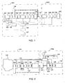
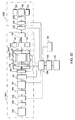
- Fig. 1 shows a system block diagram of the present invention in a systematic configuration of the active rotational power source, the first and the second dynamo-electric units, an operational clutch and an optional transmission unit.
- the split serial-parallel hybrid dual-power drive system illustrated in Fig. 1 is essentially comprised of sub units or device such as active rotational power source, dynamo-electrical units, transmission unit, transmission speed regulating unit, clutch, drive control unit, central control unit, rechargeable device, or auxiliary rechargeable device, or power driven load, each element of present system described above with its specific function as follows:
- the split serial-parallel hybrid dual-power drive system provides partial or all of the following functions:
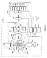
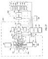
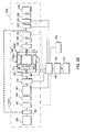
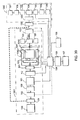
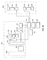
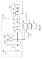
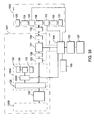
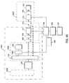
- Figs. 2 through 39 are preferred embodiments of the present invention based on those sub systems and functions, and those preferred embodiment do not limit any other applications on the same principles.
- the continuously variable transmission unit 109, the auxiliary rechargeable device 110, the startup switch 111, the startup motor 121, the central control unit 105, and the control interface 107 as illustrated in Fig. 1 are omitted while the engine functions as the active rotational power source 100 with the first dynamo-electric unit 101, the second dynamo-electric unit 103, clutches 102, 112, 122, and 132, the drive control unit 104 and the optional rechargeable device 106, the power drive load 130 are retained in those preferred embodiments illustrated in Figs. 2 through 39 to drive the load 120.
- Figs. 2 through 51 are preferred embodiment of various drive systems based on the system as illustrated in Fig. 1 with each individual preferred embodiment provides all or partial of the following operating functions:
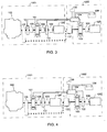
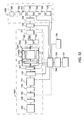
- Fig. 2 shows the block diagram of a first preferred embodiment of the split serial-parallel hybrid dual-power drive system of the present invention, essentially comprised of the first drive system 1001 and the second drive system 1002.
- the rotary part applied to output the rotational kinetic energy from the active rotational power source 100 is coupled to the optional transmission unit 129 and the optional clutch 102 to drive the first dynamo-electrical unit 101 and to further drive the respective load 120 through the clutch 112 and the optional transmission unit 109.
- the second dynamo-electrical unit 103 served as the power source for the second drive system 1002 to drive the respective load 120 through the optional clutch 122 and the optional transmission unit 109 to comprise the second drive system 1002.
- the first drive system 1001 and the second drive system 1002 constitutes the split serial-parallel hybrid dual-power drive system.
- the output terminal of the rotational kinetic energy of the active rotational power source 100, the output terminal of the transmission unit 129 coupled to, the rotary part to output the rotational kinetic energy of the clutch 102 coupled to, or the rotary part of the first dynamo-electrical unit 101 driven by the first drive system 1001 is coupled to the input end of the clutch 132; meanwhile the output terminal of the clutch 132 is coupled to the rotary part of the second dynamo-electrical unit 103 serving as the power source for the second drive system 1002, or the output terminal of the clutch 122 coupled to, the output terminal of the optional transmission unit 109 coupled to, or the input terminal of the load 120 driven by the second drive system 1002 for the control of the transmission status of the rotational kinetic energy between the first drive system 1001 and the second drive system 1002.
- Fig. 3 shows the block diagram of a second preferred embodiment of the split serial-parallel hybrid dual-power drive system of the present invention, essentially comprised of the first drive system 1001 and the second drive system 1002.
- the rotary part applied to output the rotational kinetic energy from the active rotational power source 100 is coupled to the optional transmission unit 129 and the optional clutch 102 to drive the first dynamo-electrical unit 101 and to further drive the respective load 120 through the clutch 112 and the optional transmission unit 109.
- the second dynamo-electrical unit 103 served as the power source for the second drive system 1002 drives the respective load 120 through the optional transmission unit 109.
- the first drive system 1001 and the second drive system 1002 constitutes the split serial-parallel hybrid dual-power drive system.
- the output terminal of the rotational kinetic energy of the active rotational power source 100, the output terminal of the transmission unit 129 coupled to, the rotary part to output the rotational kinetic energy of the clutch 102 coupled to, or the rotary part of the first dynamo-electrical unit 101 driven by the first drive system 1001 is coupled to the input terminal of the clutch 132; meanwhile the output terminal of the clutch 132 is coupled to the rotary part of the second dynamo-electrical unit 103 serving as the power source for the second drive system 1002, the output terminal of the optional transmission unit 109 coupled to, or the input terminal of the load 120 driven by the second drive system 1002 for the control of the transmission status of the rotational kinetic energy between the first drive system 1001 and the second drive system 1002.
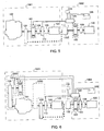
- Fig. 4 shows the block diagram of the third preferred embodiment of the split serial-parallel hybrid dual-power drive system of the present invention, essentially comprised of the first drive system 1001 and the second drive system 1002.
- the rotary part applied to output the rotational kinetic energy from the active rotational power source 100 is coupled to the optional transmission unit 129 to drive the first dynamo-electrical unit 101 and to further drive the adapted load 120 through the clutch 112 and the optional transmission unit 109.
- the second dynamo-electrical unit 103 serving as the power source for the second drive system 1002 drives the adapted load 120 through the optional clutch 122 and optional transmission unit 109.
- the first drive system 1001 and the second drive system 1002 constitutes the split serial-parallel hybrid dual-power drive system.
- the output terminal of the rotational kinetic energy of the active rotational power source 100, the output terminal of the transmission unit 129 coupled to, or the rotary part of the first dynamo-electrical unit 101 driven by the first drive system 1001 is coupled to the input terminal of the clutch 132; meanwhile the output terminal of the clutch 132 is coupled to the rotary part of the second dynamo-electrical unit 103 serving as the power source for the second drive system 1002, the output terminal of the clutch 122 coupled to, the output terminal of the optional transmission unit 109 coupled to, or the input terminal of the load 120 driven by the second drive system 1002 for the control of the transmission status of the rotational kinetic energy between the first drive system 1001 and the second drive system 1002.
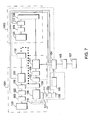
- Fig. 5 shows the block diagram of the fourth preferred embodiment of the split serial-parallel hybrid dual-power drive system of the present invention, essentially comprised of the first drive system 1001 and the second drive system 1002.
- the rotary part applied to output the rotational kinetic energy from the active rotational power source 100 is coupled to the optional transmission unit 129 to drive the first dynamo-electrical unit 101 and to further drive the respective load 120 through the clutch 112 and the optional transmission unit 109.
- the second dynamo-electrical unit 103 serving as the power source for the second drive system 1002 drives the respective load 120 through optional transmission unit 109.
- the first drive system 1001 and the second drive system 1002 constitutes the split serial-parallel hybrid dual-power drive system.
- the output terminal of the rotational kinetic energy of the active rotational power source 100, the output terminal of the transmission unit 129 coupled to the active rotational power source 100, or the rotary part of the first dynamo-electrical unit 101 driven by the first drive system 1001 is coupled to the input terminal of the clutch 132; meanwhile the output terminal of the clutch 132 is coupled to the rotary part of the second dynamo-electrical unit 103 serving as the power source for the second drive system 1002,or the output terminal of the optional transmission unit 109, or the input terminal of the load 120 driven by the second drive system 1002 for the control of the transmission status of the rotational kinetic energy between the first drive system 1001 and the second drive system 1002.
- Fig. 6 shows the block diagram of the fifth preferred embodiment of the split serial-parallel hybrid dual-power drive system of the present invention, essentially comprised of the first drive system 1001 and the second drive system 1002.
- An independent power generation unit 2000 is comprised of the optional transmission unit 109 and the optional clutch 102 provided either on the same side but not on the same shaft, not on the same side but on the same shaft, or neither on the same side nor on the same shaft of the output terminal of the load 120 driven by the active rotational power source to be coupled to the first dynamo-electrical unit 101; and the rotary part of the active rotational power source 100 is coupled to the optional transmission unit 129, the optional clutch 112 and the optional transmission 109 to drive the respective load 120 to comprise the first drive system 1001.
- the second dynamo-electrical unit 103 serving as the power source for the second drive system 1002 drives the adapted load 120 through the optional clutch 122 and optional transmission unit 109.
- the first drive system 1001 and the second drive system 1002 constitutes the split serial-parallel hybrid dual-power drive system.
- the output terminal of the rotational kinetic energy of the active rotational power source 100, or the output terminal of the transmission unit 129 coupled to, or the rotary part to output the rotational kinetic energy of the clutch 112 coupled to, or the output terminal of the optional transmission unit 109 provided to, or the rotary part of the first dynamo-electrical unit 101 driven by the first drive system 1001 is coupled to the input end of the clutch 132; meanwhile the output terminal of the clutch 132 is coupled to the rotary part of the second dynamo-electrical unit 103 serving as the power source for the second drive system 1002, the output terminal of the clutch 122 coupled to, the output terminal of the optional transmission unit 109 provided to, or the input end of the load 120 driven by the second drive system 1002 for the control of the transmission status of the rotational kinetic energy between the first drive system 1001 and the second drive system 1002.
- Fig. 7 shows the block diagram of a sixth preferred embodiment of the split serial-parallel hybrid dual-power drive system of the present invention, essentially comprised of the first drive system 1001 and the second drive system 1002.
- the rotary part to output the rotational kinetic energy from the active rotational power source 100 is coupled to the optional transmission unit 129, the optional clutch 102, and the optional transmission unit 109 to drive the first dynamo-electrical unit 101 and to further drive the adapted load 120 through the non-coaxial-aligned transmission unit 129, the clutch 112, and the optional transmission unit 109.
- the second dynamo-electrical unit 103 serving as the power source for the second drive system 1002 drives the respective load 120 through the optional clutch 122 and optional transmission unit 109.
- control of the operation of the first drive system 1001 and the second drive system 1002 constitutes the split serial-parallel hybrid dual-power drive system.
- the output terminal of the rotational kinetic energy of the active rotational power source 100, the output terminal of the transmission unit 129 coupled to, the output terminal of the transmission unit 129 coupled to, or the rotary part to output the rotational kinetic energy of the clutch 102 coupled to, the output terminal of the transmission unit 109 provided to, or the rotary part of the first dynamo-electrical unit 101 driven by the first drive system 1001 is coupled to the input end of the clutch 132; meanwhile the output terminal of the clutch 132 is coupled to the rotary part of the second dynamo-electrical unit 103 serving as the power source for the second drive system 1002, the output terminal of the clutch 122 coupled to, the output terminal of the optional transmission unit 109 provided to, or the input end of the load 120 driven by the second drive system 1002 for the control of the transmission status of the rotational kinetic energy between the first drive system 1001 and the second drive system 1002.
- Fig. 8 shows the block diagram of the seventh preferred embodiment of the split serial-parallel hybrid dual-power drive system of the present invention, essentially comprised of the first drive system 1001 and the second drive system 1002.
- the rotary part applied to output the rotational kinetic energy from the active rotational power source 100 is coupled to the optional transmission unit 129, the optional clutch 102, and the transmission unit 109 to drive the first dynamo-electrical unit 101 and to further drive the each respective load 120 by the rotary part of the first dynamo-electrical unit 101 through the transmission unit 129 to transmit the rotational kinetic energy to two or multiple clutches 112 and transmission units 109 individually selected.
- Two or multiple second drive systems are comprised of multiple second dynamo-electrical unit 103 serving as the power source for the second drive system 1002, and multiple clutches 122 and multiple transmission units 109 individually selected to drive the adapted loads 120 respectively.
- control of the operation of the first drive system 1001 and the second drive system 1002 constitutes the split serial-parallel hybrid dual-power drive system.
- the output terminal of the rotational kinetic energy of the active rotational power source 100, the output terminal of the transmission unit 129 coupled to, the rotary part to output the rotational kinetic energy of the clutch 102 coupled to, the output terminal of the optional transmission unit 109 provided to, or the rotary part of the first dynamo-electrical unit 101 driven by the first drive system 1001 is coupled to the input end of the transmission unit 129 operating on multi-shaft transmission; the output terminals of those clutches 132 are respectively coupled to rotations parts of those multiple second dynamo-electrical units 103 serving as the power source of the second drive system 1002, or respectively coupled to output terminals of those clutches 122, or coupled to output terminals of those transmission units 109 individually selected, or to input terminals of those loads respectively driven by the second drive system 1002 for the control of the transmission status of the rotational kinetic energy between the first drive system 1001 and the second drive system 1002.
- Fig. 9 shows the block diagram of the eighth preferred embodiment of the split serial-parallel hybrid dual-power drive system of the present invention, essentially comprised of multiple first drive systems 1001 and multiple second drive systems 1002.
- the rotary part to output the rotational kinetic energy from the active rotational power source 100 is coupled to the optional transmission unit 129 provided with multiple output shafts respectively coupled to two or multiple optional clutches 102 and transmission units 109 to drive two or multiple first dynamo-electrical units 101, two or multiple clutches 112, and two or multiple transmission units 109 to respectively drive the adapted loads 120 through the respective clutch 112 and the optional transmission unit 109.
- tow or multiple second dynamo-electrical units 103 serving as the power source for the second drive system 1002 respectively drive multiple adapted load 120 through multiple optional clutches 122 and multiple optional transmission units 109.
- control of the operation of the first drive system 1001 and the second drive system 1002 constitutes the split serial-parallel hybrid dual-power drive system.
- the output terminal of the rotational kinetic energy of the active rotational power source 100, the output terminal of the transmission unit 129 coupled to, or the rotary part of individual output of the transmission unit 109 operating on multi-shaft transmission coupled to, or the rotary parts to output the rotational kinetic energy of the clutches 102 respectively coupled to, each output end of the optional transmission units 109, or each rotary part of the first dynamo-electrical units 101 driven by the first drive system 1001 is coupled to the input end of the clutch 132; meanwhile the output terminal of the clutch 132 is coupled to each rotary part of the second dynamo-electrical units 103 serving as the power source for the second drive system 1002, each output end of the clutches 122 coupled to, each output end of the optional transmission units 109 coupled to, or each input end of the loads 120 driven by the second drive system 1002 for the control of the transmission status of the rotational kinetic energy between the first drive system 1001 and the second drive system 1002.
- Fig. 10 shows the block diagram of the ninth preferred embodiment of the split serial-parallel hybrid dual-power drive system of the present invention, essentially comprised of the first drive system 1001 and the second drive system 1002.
- the rotary part applied to output the rotational kinetic energy from the active rotational power source 100 is coupled to the optional transmission unit 129, the optional clutch 102, and the transmission unit 109 to drive the first dynamo-electrical unit 101 and to further drive those loads 120 adapted to both output terminals of the differential transmission unit 109 through the optional transmission unit 109, the clutch 112 and the differential transmission unit 109.
- two or multiple second dynamo-electrical units 103 serving as the power source for the second drive system 1002 respectively drive multiple adapted load 120 through each optional transmission units 109.
- control of the operation of the first drive system 1001 and the second drive system 1002 constitutes the split serial-parallel hybrid dual-power drive system.
- the output terminal of the rotational kinetic energy of the active rotational power source 100, the output terminal of the transmission unit 129 coupled to, the rotary part to output the rotational kinetic energy of the clutch 102 coupled to, the rotary part to output the rotational kinetic energy of the clutch 102 coupled to, the output terminal of the optional transmission unit 109 provided to, or the rotary part of the first dynamo-electrical unit 101 driven by the first drive system 1001 is coupled to the input end of the clutch 132; meanwhile the output terminal of the clutch 132 is coupled to the input end of the differential transmission unit 109.
- Both output ends of the differential transmission unit 109 are respectively coupled to both rotary parts of the second dynamo-electrical units 103 serving as the power source for the second drive system 1002 for the control of the transmission status of the rotational kinetic energy between the first drive system 1001 and the second drive system 1002.
- Fig. 11 shows the block diagram of the tenth preferred embodiment of the split serial-parallel hybrid dual-power drive system of the present invention, essentially comprised of the first drive system 1001 and the second drive system 1002.
- the rotary part to output the rotational kinetic energy from the active rotational power source 100 is coupled to the optional transmission unit 129, the optional clutch 102, and the transmission unit 109 to drive the first dynamo-electrical unit 101 and the rotary part of the first dynamo-electrical unit 101 is coupled to the optional transmission unit 109 and the clutch 112 to drive two loads 120 respectively adapted to both output terminals of the differential transmission unit 109.
- multiple second dynamo-electrical units 103 serving as the power source for the second drive system 1002 respectively drive multiple loads 120 adapted to both output terminals of the differential transmission unit 109 through the optional transmission unit 109, the clutch 122, and the differential transmission unit 109.
- control of the operation of the first drive system 1001 and the second drive system 1002 constitutes the split serial-parallel hybrid dual-power drive system.
- the output terminal of the rotational kinetic energy of the active rotational power source 100, the output terminal of the transmission unit 129 coupled to, the rotary part to output the rotational kinetic energy of the clutch 102 coupled to, the input end of the optional transmission unit 109, or the rotary part of the first dynamo-electrical unit 101 driven by the first drive system 1001 is coupled to the input end of the clutch 132; meanwhile the output terminal of the clutch 132 is coupled to the rotary part of the second dynamo-electrical unit 103 serving as the power source for the second drive system 1002, or the output terminal of the optional transmission unit 109, the output terminal of the clutch 122 coupled to the second drive system 1002, or to the input end of the differential transmission unit 109 located at where between the clutch 122 and the driven load 120 for the control of the transmission status of the rotational kinetic energy between the first drive system 1001 and the second drive system 1002.
- Fig. 12 shows the block diagram of the eleventh preferred embodiment of the split serial-parallel hybrid dual-power drive system of the present invention, essentially comprised of the first drive system 1001 and the second drive system 1002.
- the rotary part to output the rotational kinetic energy from the active rotational power source 100 is coupled to the optional transmission unit 129, the optional clutch 102, and the transmission unit 109 to drive the first dynamo-electrical unit 101 and the rotary part of the first dynamo-electrical unit 101 is coupled to the optional transmission unit 109 and the clutch 112, and further coupled to the optional transmission unit 129 provided with multiple input and output terminals.
- the transmission unit 129 provided with multiple input and output terminals is coupled to an auxiliary dynamo-electrical unit 1010 for the optional transmission unit 109 coupled through the clutch 122 to drive the adapted load 120.
- the second dynamo-electrical unit 103 serving as the power source for the second drive system 1002 drives the adapted load 120 through the operational transmission unit 109.
- control of the operation of the first drive system 1001 and the second drive system 1002 constitutes the split serial-parallel hybrid dual-power drive system.
- the output terminal of the rotational kinetic energy of the active rotational power source 100, the output terminal of the transmission unit 129 coupled to, the rotary part to output the rotational kinetic energy of the clutch 102 coupled to, the input end of the optional transmission unit 109 provided to or the rotary part of the first dynamo-electrical unit 101 driven by the first drive system 1001 is coupled to the input end of the clutch 132; meanwhile the output terminal of the clutch 132 is coupled to the rotary part of the second dynamo-electrical unit 103 serving as the power source for the second drive system 1002, or the output terminal of the optional transmission unit 109 provided to, or the input end of the load 120 driven by the second drive system 1002 for the control of the transmission status of the rotational kinetic energy between the first drive system 1001 and the second drive system 1002.
- Fig. 13 shows the block diagram of the twelfth preferred embodiment of the split serial-parallel hybrid dual-power drive system of the present invention, essentially comprised of the first drive system 1001 and the second drive system 1002.
- the rotary part to output the rotational kinetic energy from the active rotational power source 100 is coupled to the optional transmission unit 129, the optional clutch 102, and the transmission unit 109 to drive the first dynamo-electrical unit 101 and the rotary part of the first dynamo-electrical unit 101 is coupled to the optional transmission unit 109 and the clutch 112, and further to the optional transmission unit 129 provided with multiple input and output terminals.
- the transmission unit 129 provided with multiple input and output terminals is coupled to the auxiliary dynamo-electrical unit 1010 for the differential transmission unit 109 coupled through the clutch 122, and both output terminals of the differential transmission unit 109 drive their respectively adapted loads 120.
- two or multiple second dynamo-electrical unit 103 serving as the power source for the second drive system 1002 drives the respectively adapted loads 120 through the respective operational transmission units 109.
- control of the operation of the first drive system 1001 and the second drive system 1002 constitutes the split serial-parallel hybrid dual-power drive system.
- the output terminal of the rotational kinetic energy of the active rotational power source 100, the output terminal of the transmission unit 129 coupled to, the rotary part to output the rotational kinetic energy of the clutch 102 coupled to, the input end of the optional transmission unit 109 provided to or the rotary part of the first dynamo-electrical unit 101 driven by the first drive system 1001 is coupled to the input end of the clutch 132; meanwhile the output terminal of the clutch 132 is coupled to the input end of the differential transmission unit 109, and both output ends of the differential transmission unit 109 are respectively coupled to both rotary parts of the second dynamo-electrical units 103 serving as the power source for the second drive system 1002 for the control of the transmission status of the rotational kinetic energy between the first drive system 1001 and the second drive system 1002.
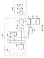
- Fig. 14 shows the block diagram of the thirteenth preferred embodiment of the split serial-parallel hybrid dual-power drive system of the present invention, essentially comprised of the first drive system 1001 and the second drive system 1002.
- the power generation unit 2000 is comprised of making the output terminal of the rotational kinetic energy of the active rotational power source 100 in the configuration of multiple output terminals either on the same side but not on the same shaft, not on the same side but on the same shaft, or neither on the same side nor on the same shaft for coupling with the optional transmission unit 129 and the optional clutch 102 to further couple to the first dynamo-electrical unit 101; and one of the multiple output terminals of the rotational kinetic energy from the active rotational power source 100 is coupled to the optional transmission unit 129, the optional clutch 112 and the optional transmission unit 109 to drive the adapted load 120 with the power generation unit 2000 to jointly constitute the first drive system 1001.
- the second dynamo-electrical unit 103 serving as the power source for the second drive system
- control of the operation of the first drive system 1001 and the second drive system 1002 constitutes the split serial-parallel hybrid dual-power drive system.
- the output terminal of the rotational kinetic energy of the active rotational power source 100, the output terminal of the transmission unit 129 coupled to, the rotary part to output the rotational kinetic energy of the clutch 112 coupled to, the output terminal of the optional transmission unit 109 provided to the first drive system 1001, or the input end of the driven load 120 is coupled to the input end of the clutch 132; meanwhile the output terminal of the clutch 132 is coupled to the rotary part of the second dynamo-electrical unit 103 serving as the power source for the second drive system 1002, or the output terminal of the clutch 122 coupled to, or the output terminal of the optional transmission unit 109 provided to, or the input end of the load 120 driven by the second drive system 1002 for the control of the transmission status of the rotational kinetic energy between the first drive system 1001 and the second drive system 1002.
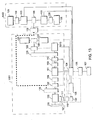
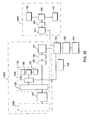
- Fig. 15 shows the block diagram of the fourteenth preferred embodiment of the split serial-parallel hybrid dual-power drive system of the present invention, essentially comprised of the first drive system 1001 and the second drive system 1002.
- the power generation unit 2000 is comprised of making the output terminal of the rotational kinetic energy of the active rotational power source 100 in the configuration of multiple output terminals either on the same side but not on the same shaft, not on the same side but on the same shaft, or neither on the same side nor on the same shaft for coupling with the optional transmission unit 129 and the optional clutch 102 to further couple to the first dynamo-electrical unit 101; and one of the output terminals of the rotational kinetic energy from the active rotational power source 100 is coupled to the optional transmission unit 129, the optional clutch 112 and the optional differential transmission unit 109 to respectively drive two loads 120 adapted to both output terminals of the differential transmission unit 109 with the power generation unit 2000 to jointly constitute the first drive system 1001.
- two or multiple second dynamo-electrical units 103 serving as the power source for the second drive system 1002 respectively drive the adapted loads 120 through the optional transmission units 109.
- the clutch 132 By switching the clutch 132 to engage or disengage status to regulate the transmission of the rotational kinetic energy between the first drive system 1001 and the second drive system 1002 are regulated to perform those functions described in System Functions 1 through 80.
- the output terminal of the rotational kinetic energy of the active rotational power source 100, the output terminal of the transmission unit 129 coupled to, the rotary part to output the rotational kinetic energy of the clutch 112 coupled to the first drive system 1001, or the output terminal of the differential transmission unit 109 is coupled to the input end of the clutch 132; meanwhile the output terminal of the clutch 132 is coupled to the input end of the differential transmission unit 109 provided in the second drive system 1002 to respectively drive two rotary parts of both second dynamo-electrical units 103 serving as the power source for the second drive system 1002 for the control of the transmission status of the rotational kinetic energy between the first drive system 1001 and the second drive system 1002.
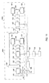
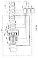
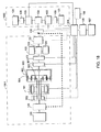
- Figs. 16 and 17 respectively illustrate the block diagrams of a fifteenth and a sixteenth preferred embodiments of the split serial-parallel hybrid dual-power drive system of the present invention.
- each is essentially comprised of the first drive system 1001 and the second drive system 1002.
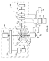
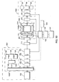
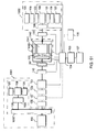
- the rotary part applied to output the rotational kinetic energy of the active rotational power source 100 is coupled to the optional transmission unit 129 and further coupled to the planet gear 803 of the planetary gear set 801.
- the rotary part of the first dynamo-electrical unit 101 is coupled to the sun gear 802 of the planetary gear set 801 while the relative motion between the rotary part and the stationary part of the first dynamo-electrical unit 101 is controlled by the drive control unit 104 to operates as a motor to output the rotational kinetic energy or as a generator to produce damping while generating power, with the effect of damping to transfer the rotational kinetic energy from the active rotational power source 100 to the external gear 804; or alternatively, by the regulating of the drive control unit 104, the stationary part and the rotary part are locked by electro-magnetic force, the function of electro-magnetic lock could be altered by the optional brake 902 with the rotary part of the first dynamo-electrical unit 101 coupled to the rotary part of the brake 902 and the stationary side of the brake 902 locked to the vehicle frame or the stationary part of the first dynamo-electrical unit 101; accordingly, the first dynamo-electrical unit 101 is in locked status allowing the
- the brake 901 is required for the active rotational power source 100 to drive the first dynamo-electrical unit 101 to operate as a generator.
- the external gear 804 of the planetary gear set 801 coupled to the input end of the clutch 112 and the rotary part of the brake 901; the stationary part of the brake 901 is locked to the frame; and the other terminal of the clutch 112 might directly output to drive the load 120 or through the optional transmission unit 109 as illustrated in Fig. 16 or the other terminal of the clutch 112 might be coupled to the input terminal of the differential transmission unit 109 as illustrated in Fig. 17 .
- Both differential output terminals of the differential transmission unit 109 are provided to drive their respective loads 120 to constitute the first drive system 1001.
- the first drive system 1001 may or may not be provided with the second dynamo-electrical unit 103 depending on requirement. While the second dynamo-electrical unit 103 is provided to the first drive system 1001, the second dynamo-electrical unit 103 illustrated in Fig. 16 may be coupled directly or through the optional transmission unit 109 to the load 120; or coupled to the input terminal of the differential transmission unit 109 driven by the clutch 112, the clutch 112 as illustrated in Fig. 17 . Wherein, the clutch 112 and the brake 901 may be separately provided or arranged in common structure.
- the second drive system 1002 adapt the second dynamo-electrical unit 103 as the power source to couple to the optional transmission unit 109 or any other transmission device for driving one or multiple load 120, or as required, the rotary part of the second dynamo-electrical unit 103 is coupled to the input terminal of the differential transmission unit 109, and both differential output terminals of the differential transmission unit 109 are provided to drive respectively adapted loads 120 to constitute the second drive system 1002.
- the clutch 132 By switching the clutch 132 to engage or disengage status for regulating the transmission of the rotational kinetic energy between the first drive system 1001 and the second drive system 1002 makes the system to perform those functions described in System Functions 1 through 80.
- the primary functions of the preferred embodiments illustrated in Figs. 16 and 17 include that while the brake 901 is closed and the clutch 112 is disengaged, the external gear 804 is locked to make the active rotational power source 100 to solely drive the sun gear 802 through the planet gear 803 thus to drive the first dynamo-electrical unit 101 to operate as a generator for driving the second dynamo-electrical unit 103 optionally adapted to the first drive system 1001, or for driving the second dynamo-electrical unit 103 adapted to the second drive system 1002, or driving both second dynamo-electrical units 103 adapted to the first drive system 1001 and the second drive system 1002 to provide the capability of generating the serial hybrid power output and/or recharge the rechargeable device 106.
- the power generated from the first dynamo-electrical unit 101 and the rechargeable device 106 jointly drive the second dynamo-electrical unit 103 in the first drive system 1001, or the second dynamo-electrical unit 103 in the second drive system 1002 or both of the second dynamo-electrical units 103 simultaneously.
- the second dynamo-electrical unit 103 in the first drive system 1001 and in the second drive system 1002 drive the load 120 jointly by utilizing the rotational kinetic energy from the active rotational power source 100 with the power from the rechargeable device 106 when the clutch 112 is engaged.
- the clutch 112 When the clutch 112 is disengaged and the first dynamo-electrical unit 101 driven by the active rotational power source 100 operates as a generator, under the control of the drive control unit 104 the second dynamo-electrical unit 103 operates in the serial hybrid power transmission mode by utilizing the power generated from the first dynamo-electrical unit 101.
- the power from the rechargeable device 106 regulated by the drive control unit 104 solely drives the second dynamo-electrical unit 103 to operate as a motor; or the power generated from the first dynamo-electrical unit 101 and that from the rechargeable device 106 jointly drive the second dynamo-electrical unit 103 to operate as a motor under the control of the drive control unit 104.
- the regenerated power of feedback braking regeneration provided by the second dynamo-electrical unit 103 recharges the rechargeable device 106 or supply power to other electrical power driven load.
- the operation between the rotary part of the optionally adapted second dynamo-electrical unit 103 of the first drive system 1001 and the load 120 may either directly or through the optional transmission unit 109 or other transmission device to drive one or multiple load 120; or as required, the rotary part of the second dynamo-electrical unit 103 is coupled to the input end of the differential transmission unit 109 for both differential output ends of the differential transmission unit 109 to drive their respectively adapted loads 120. Accordingly, the adapted load 120 is driven by the structure and operation of the first drive system 1001 as described above.
- the rotational kinetic energy output terminal of the active rotational power source 100 in the first drive system 1001, or the output terminal of the transmission unit 129 coupled to the power source 100 is coupled to the input terminal of the clutch 132.
- the output terminal of the clutch 132 is coupled to the rotary part of the second dynamo-electrical unit 103 serving as the power source for the second drive system 1002, or to the output terminal of the optional transmission unit 109 coupled to the second drive system 1002 as illustrated in Fig. 16 ; or coupled to the rotary part of the second dynamo-electrical unit 103 serving as the power source for the second drive system 1002 as illustrated in Fig. 17 , or to the input terminal of the differential transmission unit 109 of multiple loads 120 optionally adapted to the second drive system 1002 for the control of the transmission status of the rotational kinetic energy between the first drive system 1001 and the second drive system 1002.
- Fig. 18 shows a block diagram of the seventeenth preferred embodiment of the split serial-parallel hybrid dual-power drive system of the present invention.
- the preferred embodiment is comprised of the first drive system 1001 and the second drive system 1002.
- the rotary part applied to output the rotational kinetic energy from the active rotational power source 100 is coupled to the optional transmission unit 129 and the planet gear 803 of the planetary gear set 801; and the rotary part of the first dynamo-electrical unit 101 is coupled to the sun gear 802 of the planetary gear set 801.
- the operation between the rotary part and the stationary part of the first dynamo-electrical unit 101 could optionally providing the functions as a motor to output the rotational kinetic energy, or to operate as a generator to produce damping while generating power output, with the effect of the damping, the rotational kinetic energy from the active rotational power source 100 is routed to the external gear 804.
- the relative motion between the stationary part and the rotary part of the first dynamo-electrical unit 101 is locked by electro-magnetic force.
- the electro-magnetic lockup function may be replaced by the dynamic brake 902 with the rotary part of the first dynamo-electrical unit 101 coupled to the rotary part of the brake 902 and the stationary part of the brake 902 is locked to the frame or to the stationary part of the first dynamo-electrical unit 101. Accordingly, the first dynamo-electrical unit 101 is locked up, which makes the rotational kinetic energy from the active rotational power source 100 to be routed through the external gear 804.
- the brake 901 is required for the active rotational power source 100 to drive the first dynamo-electrical unit 101 to operate as a generator.
- the external gear 804 of the planetary gear set 801 is coupled to the input terminal of the clutch 112 and coupled to the rotary part of the brake 901; the stationary part of the brake 901 is locked to the frame; and the other terminal of the clutch 112 may directly drive the load 120 or through the optional transmission unit 109.
- the first drive system 1001 may or may not be provided with the second dynamo-electrical unit 103. If the second dynamo-electrical unit 103 is provided to the first drive system 1001, the second dynamo-electrical unit 103 may coupled to the load 120 directly or through the optional transmission unit 109; or coupled to the input terminal of the differential transmission unit 109 driven by the clutch 112, the clutch 112 as illustrated in Fig. 17 . Wherein, the clutch 112 and the brake 901 may be separately provided or arranged in common structure.
- the second drive system 1002 equipped with multiple second dynamo-electrical units 103 as the power source to respectively coupled to the optional transmission unit 109 or any other transmission device to drive respectively adapted loads 120 to constitute the second drive system 1002.
- the primary operation functions of the preferred embodiments illustrated in Fig. 18 include that when the brake 901 is closed and the clutch 112 is disengaged, the external gear 804 is locked to make the active rotational power source 100 to solely drive the sun gear 802 through the planet gear 803 thus to drive the first dynamo-electrical unit 101 to operate as a generator for driving the second dynamo-electrical unit 103 optionally adapted to the first drive system 1001, or for driving the second dynamo-electrical unit 103 adapted to the second drive system 1002, or driving both second dynamo-electrical units 103 adapted to the first drive system 1001 and the second drive system 1002 to provide the capability of generating the serial hybrid power output and/or recharge the rechargeable device 106.
- the power generated from the first dynamo-electrical unit 101 and from the rechargeable device 106 jointly drive the second dynamo-electrical unit 103 in the first drive system 1001, or the second dynamo-electrical unit 103 in the second drive system 1002 or both of the second dynamo-electrical units 103 simultaneously.
- the clutch 112 When the clutch 112 is disengaged, the brake 901 is closed, the brake 902 is disengaged, and the first dynamo-electrical unit 101 is driven by the active rotational power source 100 through the planet gear set 801 to operate as a generator, under the control of the drive control unit 104 the second dynamo-electrical unit 103 operates in the serial hybrid power transmission mode by utilizing the power generated from the first dynamo-electrical unit 101.
- the power from the rechargeable device 106 regulated by the drive control unit 104 solely drives the second dynamo-electrical unit 103 to operate as a motor; or the power generated from the first dynamo-electrical unit 101 and that from the rechargeable device 106 jointly drive the second dynamo-electrical unit 103 to operate as a motor under the control of the drive control unit 104.
- the regenerated power of feedback braking regeneration provided by the second dynamo-electrical unit 103 recharges the rechargeable device 106 or supply power to other electrical power driven load.
- the operation between the rotary part of the second dynamo-electrical unit 103 optionally adapted to the first drive system 1001 and the load 120 may either directly or through the optional transmission unit 109 or other transmission device drive one or multiple load 120; or as required, the rotary part of the second dynamo-electrical unit 103 is coupled to the input terminal of the differential transmission unit 109 for both differential output terminals of the differential transmission unit 109 to drive their respectively adapted loads 120. Accordingly, the adapted load 120 is driven by the structure and operation of the first drive system 1001 as described above.
- the rotational kinetic energy output terminal of the active rotational power source 100 in the first drive system 1001, or the output terminal of the transmission unit 129 coupled to the power source 100 is coupled to the input terminal of the clutch 132.
- the output terminal of the clutch 132 is coupled to the input terminal of the differential transmission unit 109 optionally provided to the second drive system 1002 for the control of the transmission status of the rotational kinetic energy between the first drive system 1001 and the second drive system 1002.
- Fig. 19 shows a block diagram of the eighteenth preferred embodiment of the split serial-parallel hybrid dual-power drive system of the present invention.
- the construction of the first drive system 1001 and the second drive system 1002 for the preferred embodiment illustrated in Fig. 19 is identical with that given in Fig. 16 .
- Fig. 20 shows a block diagram of the nineteenth preferred embodiment of the split serial-parallel hybrid dual-power drive system of the present invention.
- the construction of the first drive system 1001 and the second drive system 1002 for the preferred embodiment illustrated in Fig. 20 is identical with that given in Fig. 17 .
- the input terminal of the clutch 132 respectively illustrated in Figs.
- 19 and 20 is coupled to the rotary part of the second dynamo-electrical unit 103 adapted to the first drive system 1001, or to the input terminal or output terminal of the transmission unit 109 adapted to the second dynamo-electrical unit 103; and the output terminal of the clutch 132 is coupled to the rotary part of the second dynamo-electrical unit 103 serving as the power source for the second drive system 1002, or to the transmission unit 109 optionally adapted to the rotary part of the second dynamo-electrical unit 103, or to the input terminal of the differential transmission unit 109.
- the clutch 132 may be optionally provided to control the transmission status between the first drive system 1001 and the second drive system 1002 while the transmission unit 109 may be optionally provided to the output terminal of the active rotational power source 100 to drive the planet gear 803 of the planetary gear set 801.
- Fig. 21 shows a block diagram of the twentieth preferred embodiment of the split serial-parallel hybrid dual-power drive system of the present invention.
- the construction of the first drive system 1001 and the second drive system 1002 for the preferred embodiment illustrated in Fig. 21 is identical with that given in Fig. 18 .
- the clutch 132 may be optionally provided to control the transmission status of the rotational kinetic energy between the first drive system 1001 and the second drive system 1002 while transmission unit 109 may be optionally provided to the output terminal of the active rotational power source 100 to drive the planet gear 803 of the planetary gear set 801.
- the differential function of the planetary gear set adapted to the first drive system 1001 as respectively illustrated in Figs. 16 , 17 , 18 , 19 , 20 , and 21 may be replaced by the rotational gear set 1030 working on the same principles but provided in different structure.
- Fig. 22 shows the twenty-first preferred embodiment of the present invention with the differential gear set to replace the separation type of the planet gear set as illustrated in Fig. 16 .
- Fig. 23 shows the twenty-second preferred embodiment of the present invention with the differential gear set to replace the separation type of the planet gear set as illustrated in Fig. 17 .
- the rotational gear set 1030 substitutes the planetary gear set 801.
- the first input and output terminal 501 is coupled to the first input and output gear set 511 and to the input and output terminal of the rotational kinetic energy from the active rotational power source 100, or to the optionally provided transmission unit 129 while the transmission unit 129 is driven by the active rotational power source 100.
- the second input and output terminal 502 is coupled to the first dynamo-electrical unit 101, the brake 902 and the second input and output gear set 512.
- Both of the first and the second input and output gear sets 511, 512 are coupled to the differential gear set 5130 for a rotary arm 5131 to draw the differential output gear set 5132 and the third input and output gear set 513 for the third input and output gear set 513 to drive the third input and output terminal 503 and the rotary part of the brake 901 and the clutch 112 coupled to the third input and output terminal 503.
- the other terminal of the clutch 112 might drives the load 120 directly or through the optionally provided transmission unit 109.
- the other terminal of the clutch 112 is coupled to the input terminal of the differential transmission unit 109 for both differential output terminals of the differential transmission unit 109 to drive their respectively adapted loads 120 to constitute the first drive system 1001.
- the first drive system 1001 may be optionally provided with a second dynamo-electrical unit 103. If the second dynamo-electrical unit 103 is deployed, that illustrated in Fig. 22 may coupled to the load 120 directly or through the optionally provided transmission unit 109; and that illustrated in Fig. 23 may coupled to the input terminal of the differential transmission unit 109 driven by the clutch 112.
- the second drive system 1002 with the second dynamo-electrical unit 103 as the power source for the second drive system 1002 is coupled to the optionally provided transmission unit 109 or any other transmission device to drive one or multiple load 120; or alternatively, the rotary part of the second dynamo-electrical unit 103 is coupled to the input terminal of the differential transmission unit 109 for both differential output terminals of the differential transmission unit 109 to drive their respectively adapted loads 120 to constitute the second drive system 1002.
- the transmission status of the rotational kinetic energy between the first drive system 1001 and the second drive system 1002 is controlled by engaging or disengaging the clutch 132 to provide those functions described in System Functions 1 through 80.
- the primary operating functions of both preferred embodiments illustrated in Figs. 22 and 23 include that while the clutch 112 is disengaged, the brake 901 is closed and the brake 902 is disengaged, the active rotational power source 100 drives the first dynamo-electrical unit 101 through the rotational gear set 1030 to operate as a generator, through the control of the drive control unit 104, the power generated by the first dynamo-electrical unit 101 is applied to drive the second dynamo-electrical unit 103 in the first drive system 1001, or that in the second drive system 1002, or both at the same time to operate as a motor for driving the load to provide the functions of a serial hybrid power transmission.
- the second dynamo-electrical unit 103 operating as a motor to drive the load 120 by receiving the power from the first dynamo-electrical unit 101 and the rechargeable device 106.
- the second dynamo-electrical unit 103 operates as a motor to drive the load 120 by receiving the power from the rechargeable device 106.
- the brake 901 While the brake 901 is disengaged, the brake 902 is engaged and the clutch 112 is also engaged, under the control of the drive control unit 104, the second dynamo-electrical unit 103 operating as a motor to drive the load 120 jointly with the rotational kinetic energy from the active rotational power source 100 by receiving the power from the rechargeable device 106.
- the second dynamo-electrical unit 103 performs power regeneration by recycling the kinetics to recharge the rechargeable device 106 or supply power to any other electrical power driven load 130.
- the rotational kinetic energy output terminal of the active rotational power source 100 in the first drive system 1001, or the output terminal of the transmission unit 129 coupled to the active rotational power source 100 is coupled to the input terminal of the clutch 132 while the output terminal of the clutch 132 is coupled to the rotary part of the second dynamo-electrical unit 103 as the power source of the second drive system 1002, or to the output terminal of the optionally provided transmission unit 109 as illustrated in Fig. 22 , or coupled to the rotary part of the second dynamo-electrical unit 103 of the power source of the second drive system 1002, or to the input terminal of the differential transmission unit 109 of multiple loads 120 optionally provided to the second drive system 1002 as illustrated in Fig. 23 for the control of the transmission status of the rotational kinetic energy between the first drive system 1001 and the second drive system 1002.
- Fig. 24 shows the twenty-third preferred embodiment of the present invention with the differential gear set to replace the separation type of the planetary gear set as illustrated in Fig. 18 .
- the rotational gear set 1030 substitutes the planet gear set 801.
- the first input and output terminal 501 is coupled to the first input and output gear set 511, and to the input and output terminal of the rotational kinetic energy from the active rotational power source 100, or to the optionally provided transmission unit 129 while the transmission unit 129 is driven by the active rotational power source 100.
- the second input and output terminal 502 is coupled to the first dynamo-electrical unit 101, the brake 902 and the second input and output gear set 512.
- Both of the first and the second input and output gear sets 511, 512 are coupled to the differential gear set 5130 for a rotary arm 5131 to draw the differential output gear set 5132 and the third input and output gear set 513 for the third input and output gear set 513 to drive the third input and output terminal 503 and the rotary part of the brake 901 and the clutch 112 coupled to the third input and output terminal 503.
- the other terminal of the clutch 112 is coupled to the input terminal of the differential transmission unit 109 with both differential output terminals of the differential transmission unit 109 to drive their respectively adapted loads 120 to constitute the first drive system 1001.
- the first drive system 1001 may be optionally provided with a second dynamo-electrical unit 103. If the second dynamo-electrical unit 103 is deployed, it may be coupled to the clutch 112 or to the input of the differential transmission unit 109 driven by the clutch 112.
- Each of the multiple second dynamo-electrical units 103 serving as the power source for the second drive system 1002 is coupled to the optionally provided transmission unit 109 or any other transmission device to drive one or multiple load 120 to constitute the second drive system 1002.
- the transmission status of the rotational kinetic energy between the first drive system 1001 and the second drive system 1002 is controlled by engage or disengage the clutch 132 to provide those functions described in System Functions 1 through 80.
- the primary operation functions of both preferred embodiments illustrated in Fig. 24 include that when the clutch 112 is disengaged, the brake 901 is closed and the brake 902 is disengaged, the active rotational power source 100 drives through the rotational gear set 1030 the first dynamo-electrical unit 101 to operate as a generator; and either or both of the second dynamo-electrical unit 103 in the first drive system 1001 and that in the second drive system 1002 receives the power generated from the first dynamo-electrical unit 101 to operate as a motor as controlled by the drive control unit 104 to drive the load and provide those functions of the series combine power.
- the second dynamo-electrical unit 103 by accepting the power from the first dynamo-electrical unit 101 and the rechargeable device 106 operates as a motor to drive the load 120 through the control by the drive control unit 104; or the second dynamo-electrical unit 103 by receiving the power from the rechargeable device 106 operates as a motor to drive the load 120 through the control by the drive control unit 104.
- the brake 901 When the brake 901 is disengaged, the brake 902 is closed up and the clutch 112 is also closed up, the second dynamo-electrical unit 103 by accepting the power from the rechargeable device 106 operates as a motor to jointly drive the load 120 through the control by the drive control unit 104 and the rotational kinetic energy from the active rotational power source 100.
- the second dynamo-electrical unit 103 executes power regeneration by reclaiming the kinetics to recharge the rechargeable device 106 or supply power to any other electrical power driven load 130.
- the rotational kinetic energy output terminal of the active rotational power source 100 in the first drive system 1001, or the output terminal of the transmission unit 129 coupled to the first drive system 1001 is coupled to the input terminal of the clutch 132 while the output terminal of the clutch 132 is coupled to the input of the differential transmission unit 109 of multiple loads 120 optionally provided to the second drive system 1002 for the control of the transmission status of the rotational kinetic energy between the first drive system 1001 and the second drive system 1002.
- Fig. 25 shows a block diagram of the twenty-fourth preferred embodiment of the present invention.
- the differential gear substitutes the separation type of the preferred embodiment of the planetary gear set as illustrated in Fig. 19 .
- the construction of the first drive system 1001 and the second drive system 1002 is identical with illustrated in Fig. 22 .
- Fig. 26 shows a block diagram of the twenty-fifth preferred embodiment of the present invention.
- the differential gear substitutes the separation type of the preferred embodiment of the planetary gear set as illustrated in Fig. 20 .
- the construction of the first drive system 1001 and the second drive system 1002 is identical with that as illustrated in Fig. 23 .
- the input terminal of the clutch 132 as respectively illustrated in Figs. 25 and 26 is coupled to the rotary part of the second dynamo-electrical unit 103 adapted to the first drive system 101, or to the input terminal or output terminal of the transmission unit 109 adapted to the second dynamo-electrical unit 103 while the output terminal of the clutch 132 is coupled to the rotary part of the second dynamo-electrical unit 103 serving as the power source for the second drive system 1002, or to the transmission unit 109 optionally adapted to the rotary part of the second dynamo-electrical unit 103, or to the input terminal of the differential transmission unit 109.
- the clutch 132 may be optionally provided to control the transmission status of the rotational kinetic energy between the first drive system 1001 and the second drive system 1002 while the output terminal of the active rotational power source 100 may be optionally provided with a transmission unit 109 to further drive the planet gear 803 of the planetary gear set 801.
- Fig. 27 shows a block diagram of the twenty-sixth preferred embodiment of the present invention.
- the differential gear substitutes the separation type of the preferred embodiment of the planetary gear set as illustrated in Fig. 21 .
- the construction of the first drive system 1001 and the second drive system 1002 is identical with that as illustrated in Fig. 24 .
- the clutch 132 may be optionally provided to control the transmission status of the rotational kinetic energy between the first drive system 1001 and the second drive system 1002 while the output terminal of the active rotational power source 100 may be optionally provided with a transmission unit 109 to further drive the planet gear 803 of the planetary gear set 801.
- the differential function provided by the planetary gear set adapted to the first drive unit 1001 respectively illustrated in Figs. 16 , 17 , 18 , 19 , 20 and 21 is replaced with a dual motion dynamo-electrical unit providing the similar functions but different structure.
- Fig. 28 shows a block diagram of the twenty-seventh preferred embodiment of the present invention, wherein, the dual motion dynamo-electrical unit substitutes the split installed planetary gear set illustrated in Fig. 16 ; and Fig. 29 shows a block diagram of the twenty-eighth preferred embodiment of the present invention, wherein, the dual motion dynamo-electrical unit substitute the split installed planetary gear set illustrated in Fig. 16 .
- the rotary part to output the rotational kinetic energy of the active rotational power source 100 is coupled to the transmission unit 129, the clutch 102 and the transmission unit 109 optionally provided to drive the rotary part of the first dynamo-electrical unit 101.
- the dual motion dynamo-electrical unit 1040 could be implemented in the form of AC or DC, brush or brushless, synchronous or asynchronous.
- the dual motion dynamo-electrical unit 1040 made in a cylinder, disk or cone structure is comprised of the first rotary part 1041 and the second rotary part 1042 with the controllable clutch 122 arranged between the first and the second rotary parts 1041, 1042.
- the first rotary part 1041 is coupled to the rotary part of the brake 901, and through the clutch 112 to couple with the rotary part of the first dynamo-electrical unit 101.
- the stationary part of the brake 901 is locked to the frame.
- the second rotary part 1042 of the dual motion dynamo-electrical unit 1040 as illustrated in Fig. 28 drives the load 120 directly or through the optionally provided transmission unit 109, or as illustrated in Fig. 29 , coupled to the input terminal of the differential transmission unit 109 with both differential output terminals of the differential transmission unit 109 to drive their respectively adapted loads 120 to constitute the first drive system 1001.
- the second dynamo-electrical unit 103 may be or may not be provided to the first drive system 1001. While the second dynamo-electrical unit 103 is provided, its rotary part as illustrated in Fig. 28 is coupled to the load 120 directly or through the optionally provided transmission unit 109, or to the differential transmission unit 109 driven by the second rotary part 1042 as illustrated in Fig. 29 .
- the second drive system 1002 deploy the second dynamo-electrical unit 103 as the power source to drive one or multiple load 120 through the optionally provided transmission unit 109 or any other transmission device; or the rotary part of the second dynamo-electrical unit 103 is coupled to the input terminal of the differential transmission unit 109 with both differential output terminals of the differential transmission unit 109 to drive their respectively adapted loads 120 to constitute the second drive system 1002.
- the clutch 132 between engaging or disengaging status to regulate the rotational kinetic energy between the first drive system 1001 and the second drive system 1002 to provide those functions described in System Functions 1 through 80.
- the primary functions of both preferred embodiments given in Figs. 28 and 29 include that while the clutch 112 is disengaged and the brake 901 is closed, the active rotational power source 100 drives the first dynamo-electrical unit 101 to operate as a generator; and either or both of the second dynamo-electrical unit 103 in the first drive system 1001 and that in the second drive system 1002 receives the power generated from the first dynamo-electrical unit 101 to operate as a motor controlled by the drive control unit 104 to drive the load and provide the functions of serial hybrid power transmission.
- the second dynamo-electrical unit 103 receive the power from the first dynamo-electrical unit 101 and the rechargeable device 106 to operate as a motor to drive the load 120; or the second dynamo-electrical unit 103 with the power from the rechargeable device 106 to operate as a motor to drive the load.
- the second dynamo-electrical unit 103 receive the power from the rechargeable device 106 to operate as a motor to jointly drive the load 120 with the rotational kinetic energy from the active rotational power source 100.
- the second dynamo-electrical unit 103 performs power regeneration by recycling the feedback brake kinetics to recharge the rechargeable device 106 or supply power to any other electrical power driven load 130.
- the rotational kinetic energy output terminal of the active rotational power source 100 in the first drive system 1001, or the output terminal of the transmission unit 129 coupled to the first drive system 1001 is coupled to the input terminal of the clutch 132 while the output terminal of the clutch 132 is coupled to rotary part of the second dynamo-electrical unit 103 serving as the power source for the second drive system 1002, or to the output terminal of the transmission unit 109 optionally provided as illustrated in Fig. 28 ; or coupled to the rotary part of the second dynamo-electrical unit 103 serving as the power source for the second drive system 1002, or to the input terminal of the differential transmission units 109 of multiple loads 120 coupled to the second drive system 1002 optionally provided as illustrated in Fig. 29 for the control of the transmission status of the rotational kinetic energy between the first drive system 1001 and the second drive system 1002.
- Fig. 30 shows the block diagram of the twenty-ninth preferred embodiment of the present invention.
- the dual motion dynamo-electrical unit substitutes the split planetary gear set illustrated in Fig. 18 .
- the rotary part applied to output the rotational kinetic energy of the active rotational power source 100 is coupled to the transmission unit 129, the clutch 102 and the transmission unit 109 optionally provided to drive the rotary part of the first dynamo-electrical unit 101.
- a dual motion dynamo-electrical unit 1040 made in the form of AC or DC, brush or brushless, synchronous or asynchronous is provided.
- the dual motion dynamo-electrical unit 1040 made in a cylinder, disk or cone shape is comprised of the first rotary part 1041 and the second rotary part 1042 with the controllable clutch 122 installed between the first and the second rotary parts 1041, 1042.
- the first rotary part 1041 is coupled to the rotary part of the brake 901, and further to the rotary part of the first dynamo-electrical unit 101 through the clutch 112.
- the stationary part of the brake 901 is locked to the frame.
- the second rotary part 1042 of the dual motion dynamo-electrical unit 1040 is coupled to the input terminal of the differential transmission unit 109 with both differential outputs of the differential transmission unit 109 to drive their respectively adapted loads 120 to constitute the first drive system 1001.
- the second dynamo-electrical unit 103 may be or may not be provided to the first drive system 1001. When the second dynamo-electrical unit 103 is provided, it is coupled to the second rotary part 1042 or to the input terminal of the differential transmission unit 109 driven by the second rotary part 1042.
- the second drive system 1002 deployed multiple second dynamo-electrical units 103 as the power source drives separately coupled to the optionally transmission unit 109 or any other transmission device to drive their respectively adapted loads 120 to constitute the second drive system 1002.
- the clutch 132 to be disengaged or engaged to regulate the transmission status of the rotational kinetic energy between the first drive system 1001 and the second drive system 1002 to provide those functions described in System Functions 1 through 80.
- the primary functions of the preferred embodiment given in Fig. 30 and 29 include that when the clutch 112 is disengaged, and the brake 901 is closed, the active rotational power source 100 drives the first dynamo-electrical unit 101 to operate as a generator; under the regulation of the drive control unit 104, either or both of the second dynamo-electrical unit 103 in the first drive system 1001 and that in the second drive system 1002 receive power generated from the first dynamo-electrical unit 101 to operate as a motor to drive the load and provide the function of the serial hybrid power transmission.
- the second dynamo-electrical unit 103 receive the power from the first dynamo-electrical unit 101 and the rechargeable device 106 operates as a motor to drive the load 120.
- the second dynamo-electrical unit 103 When both clutches 102, 112 are engaged, and both of the clutch 122 and the brake 901 are disengaged, under the control of the drive control unit 104 the second dynamo-electrical unit 103 receive the power from the rechargeable device 106 operates as a motor for driving the load 120; or the second dynamo-electrical unit 103 receive the power from the rechargeable device 106 to operate as a motor to jointly drive the load 120 with the rotational kinetic energy from the active rotational power source 100.
- the second dynamo-electrical unit 103 performs power regeneration by recycling the feedback brake kinetics to recharge the rechargeable device 106 or supply power to any other electrical power driven load 130.
- the rotational kinetic energy output terminal of the active rotational power source 100 in the first drive system 1001, or the output terminal of the transmission unit 129 coupled to the first drive system 1001 is coupled to the input terminal of the clutch 132 while the output terminal of the clutch 132 is coupled to the input terminal of the differential transmission unit 109 of multiple second dynamo-electrical unit 103 coupled to the optionally provided second drive system 1002 for the control of the transmission status of the rotational kinetic energy between the first drive system 1001 and the second drive system 1002.
- Fig. 31 shows the block diagram of the thirtieth preferred embodiment of the present invention.
- the dual motion dynamo-electrical unit substitutes the split planetary gear set illustrated in Fig. 19 .
- the construction of the first drive system 1001 and the second drive system 1002 of the preferred embodiment illustrated in Fig. 31 is identical with that illustrated in Fig. 28 .
- Fig. 32 shows the block diagram of the thirty-first preferred embodiment of the present invention.
- the dual motion dynamo-electrical unit substitutes the split planetary gear set illustrated in Fig. 20 .
- the construction of the first drive system 1001 and the second drive system 1002 of the preferred embodiment illustrated in Fig. 32 is identical with that illustrated in Fig. 29 .
- the transmission unit 109 may be also optionally provided to the output terminal of the active rotational power source 100 in the system respectively illustrated in Figs. 31 and 32 so to further drive the planet gear 803 of the planetary gear set 801.
- the clutch 132 is optionally provided for the control of the transmission status of the rotational kinetic energy between the first drive system 1001 and the second drive system 1002. The difference respectively between both preferred embodiment given in Figs. 31 and 32 and those in Figs.
- the input terminal of the clutch 132 respectively of the thirtieth and the thirty-first preferred embodiments is coupled to the rotary part of the second dynamo-electrical unit 103 optionally adapted to the first drive system 1001, or to the input terminal or output terminal of the transmission unit 109 adapted to the second dynamo-electrical unit 103 while the output terminal of the clutch 132 is coupled to the rotary part of the second dynamo-electrical unit 103 serving as the power source for the second drive system 1002, or to the transmission unit 109 optionally provided to the rotary part of the second dynamo-electrical unit 013 in the second drive system, or to the input terminal of the differential transmission unit 109.
- Fig. 33 shows the block diagram of the thirty-second preferred embodiment of the present invention.
- the dual motion dynamo-electrical unit substitutes the split planet gear set illustrated in Fig. 21 .
- the construction of the first drive system 1001 and the second drive system 1002 of the preferred embodiment illustrated in Fig. 33 is identical with that illustrated in Fig. 30 .
- the transmission unit 109 may be also optionally provided to the output terminal of the active rotational power source 100 in the system illustrated in Figs. 33 so to further drive the planet gear 803 of the planetary gear set 801.
- the clutch 132 is optionally provided for the control of the transmission status of the rotational kinetic energy between the first drive system 1001 and the second drive system 1002. The difference respectively between both preferred embodiment given in Figs.
- the input terminal of the clutch 132 respectively of the thirtieth and the thirty-first preferred embodiments is coupled to the rotary part of the second dynamo-electrical unit 103 optionally adapted to the first drive system 1001, or to the input terminal or output terminal of the transmission unit 109 adapted to the second dynamo-electrical unit 103 while the output terminal of the clutch 132 is coupled to the input terminal of the differential transmission unit 109 optionally provided to the second drive system 1002 with both output terminals of the differential transmission unit 109 to be respectively coupled to the rotary parts of multiple second dynamo-electrical units 103 serving as the power source for the second drive system 1002.
- the output terminal of the active rotational power source 100 in the split serial-parallel hybrid dual-power drive system is firstly coupled to the clutch 1020.
- the clutch 1020 is operating by manual, mechanical force, eccentric force, air pressure, or hydraulic flow force, or electro-magneto controlled clutch, or single way clutch, or coupler with torque control capability, or any other transmission device that transmits or interrupt the mechanical rotational kinetic energy transfer.
- the clutch 1020 is coupled to the transmission unit 109 serving as the pilot drive unit 1000 and coupled to the transmission device 129 and the load 120 to control the load 120 driven by the pilot drive unit 1000 which generates the rotational kinetic energy.
- the power generated by the first dynamo-electrical unit 101 driven by the active rotational power source 100 drives the second dynamo-electrical unit 103 in the second drive system 1002 directly or under the regulation of the drive control unit 104 to provide the capability of serial hybrid power transmission, or to operate the primary functions of the parallel hybrid power transmission and other operations described in System Functions 1 through 80 under the regulation of a control system.
- Fig. 34 is the first block diagram showing that a pilot drive unit is provided to the output terminal of the active rotational power source of the present invention
- Fig. 35 is a second block diagram showing that a pilot drive unit is provided to the output terminal of the active rotational power source of the present invention.
- Each of both preferred embodiments illustrated in Figs. 34 and 35 essentially includes the pilot drive unit 1000 comprised of the output terminal of the active rotational power source 100 that is firstly coupled to the transmission unit 129, the auxiliary clutch 1020, and a transmission unit 109 of the prior art optionally provided to drive the load 120.
- the clutch 1020 is provided to control the transmission status of the rotational kinetic energy between the active rotational power source 100 and the load 120 to the pilot drive unit 1000.
- the pilot drive unit 1000 may be optionally provided to any other output terminal of the active rotational power source 100.
- the clutch 102 and the transmission unit 109 are optionally provided to the same output terminal or different output terminals of the active rotational power source 100 to drive the first dynamo-electrical unit 101 to constitute the first drive system 1001 with the pilot drive unit 1000.
- the second drive system 1002 with the second dynamo-electrical unit 103 as the power source is coupled to the transmission unit 109 of the prior art optionally provided for driving one or multiple loads 120 adapted to the transmission unit 109 to constitute the second drive system 1002.
- the input terminal of the clutch 1020 in the pilot drive unit 1000 is coupled to the output terminal of the transmission unit 129 driven by the active rotational power source 100, or to another output terminal of the active rotational power source 100.
- the transmission unit 109 coupled between the clutch 1020 and the load 120 may be comprised of the transmission unit 109 which provides the capability of controllable multistage transmission, continuously variable transmission, reversing or idling function as illustrated in Fig. 34 to drive the load 120, or may be comprised of the transmission unit 109 which provides with the capability of controllable multistage transmission, continuously variable transmission, reversing or idling function and multiple shafts for differential output as illustrated in Fig. 35 to drive the loads 120 respectively adapted to each differential output terminal for differential operation.
- the second drive system 1002 with the second dynamo-electrical unit 103 as the power source is coupled to the transmission unit 109 of the prior art optionally provided for driving one or multiple loads 120 adapted to the transmission unit 109 to constitute the second drive system 1002.
- the transmission unit 109 driven by the second dynamo-electrical unit 103 may be provided with the capability of controllable multistage transmission, continuously variable transmission, reversing or idling function as illustrated in Fig. 34 to drive the load 120, or in the form of the transmission unit 109 that is provided with the capability of controllable multistage transmission, continuously variable transmission, reversing or idling function and multiple shafts for the operation of differential output as illustrated in Fig. 35 to drive the loads 120 respectively adapted to each differential output terminal for differential transmission.
- the clutch 102 coupled to the output terminal of the active rotational power source 100 through the transmission unit 129, the optionally provided transmission unit 109 and the first dynamo-electrical unit 101 may coupled with the first drive system 1001, or coupled with the second drive system 1002 or provide standalone operation.
- the operation of the active rotational power source 100 may further include driving the first dynamo-electrical unit 101 by the active rotational power source 100 to operate as a generator with the power generated to drive the second dynamo-electrical unit 103 in the second drive system 1002 to produce the rotational kinetic energy to drive the load 120 for the system to provide the serial hybrid power transmission.
- the active rotational power source 100 drives the first dynamo-electrical unit 101 to operate as a generator with the power generated to recharge the rechargeable device 106 or supply power to any other electrical power driven load 130 (including any externally connected unspecified load), and drive the second dynamo-electrical unit 103 in the second drive system 1002 to drive the load 120.
- the active rotational power source 100 drives the first dynamo-electrical unit 101 to operate as a generator to recharge the rechargeable device 106 or to supply power to other electrical power driven load 130 (including any externally connected unspecified load).
- the first dynamo-electrical unit 101 operates as a generator with the power from the rechargeable device 106 to jointly drive the second dynamo-electrical unit 103 to produce the rotational kinetic energy to drive the load 120 or supply power to any other electrical power driven load 130 (including any externally connected unspecified load).
- the power from the rechargeable device 106 drives the second dynamo-electrical unit 103 in the second drive system 1002 to generate the rotational kinetic energy for driving the load.
- the power from the rechargeable device 106 drives the second dynamo-electrical unit 103 in the second drive system 1002 to generate the rotational kinetic energy for jointly driving the load with the power from the active rotational power source 100.
- the recycled power from feedback braking regeneration by the first dynamo-electrical unit 101 or the second dynamo-electrical unit 103 recharges the rechargeable device 106 or supply power to any other electrical power driven load 130 (including any externally connected unspecified load).
- Fig. 36 is the third block diagram showing that a pilot drive unit is provided to the output terminal of the active rotational power source of the present invention.
- the preferred embodiment illustrated in Fig. 36 includes the pilot drive unit 1000 comprised of the output terminal of the active rotational power source 100 that is coupled first to the transmission unit 129, the auxiliary clutch 1020, and a transmission unit 109 of the prior art optionally provided to drive the load 120.
- the clutch 1020 is provided to control the transmission status of the rotational kinetic energy between the active rotational power source 100 and the load 120 to the pilot drive unit 1000.
- the pilot drive unit 1000 may be optionally provided to any other output terminal of the active rotational power source 100.
- the clutch 102 and the transmission unit 109 are optionally provided to the same output terminal or different output terminals of the active rotational power source 100 to drive the first dynamo-electrical unit 101 to constitute the first drive system 1001 with the pilot drive unit 1000.
- the input terminal of the clutch 1020 in the pilot drive unit 1000 is coupled to the output terminal of the transmission unit 129 driven by the active rotational power source 100, or to another output terminal of the active rotational power source 100.
- the input terminal of the clutch 1020 is coupled to the output terminal of the transmission unit 129 driven by the active rotational power source 100 or to the other output terminal of the active rotational power source 100.
- the transmission unit 109 coupled between the clutch 1020 and the load 120 may be comprised of the transmission unit 109 which provides the capability of controllable multistage transmission, continuously variable transmission, reversing or idling function or may be comprised of the transmission unit 109 which provides the capability of controllable multistage transmission, continuously variable transmission, reversing or idling function and multiple shafts for the operation of differential output to drive the loads 120 respectively adapted to each differential output terminal for differential operation.
- the second drive system 1002 with the second dynamo-electrical unit 103 as the power source is coupled to the transmission unit 109 of the prior art optionally provided for driving one or multiple loads 120 adapted to the transmission unit 109 to constitute the second drive system 1002.
- the transmission unit 109 driven by the second dynamo-electrical unit 103 may be provided with the capability of controllable multistage transmission, continuously variable transmission, reversing or idling function as illustrated in Fig. 34 to drive the load 120, or in the form of the transmission unit 109 that is provided with the capability of controllable multistage transmission, continuously variable transmission, reversing or idling function and multiple shafts for the operation of differential output to drive the loads 120 respectively adapted to each differential output terminal for differential operation.
- the clutch 102 coupled to the output terminal of the active rotational power source 100 through the transmission unit 129, the optionally provided transmission unit 109 and the first dynamo-electrical unit 101 may coupled with the first drive system 1001, or coupled with the second drive system 1002 or provide standalone operation.
- the operation of the active rotational power source 100 may further drive the first dynamo-electrical unit 101 by the active rotational power source 100 to operate as a generator with the power generated to drive multiple second dynamo-electrical units 103 in the second drive system 1002 to produce the rotational kinetic energy to drive the load 120 for the system to provide the serial hybrid power transmission.
- the active rotational power source 100 drives the first dynamo-electrical unit 101 to operate as a generator with the power generated to recharge the rechargeable device 106 or supply power to any other electrical power driven load 130 (including any externally connected unspecified load), and drive multiple second dynamo-electrical units 103 in the second drive system 1002 to drive the load 120.
- the active rotational power source 100 drives the first dynamo-electrical unit 101 to operate as a generator with the power generated to recharge the rechargeable device 106 or to supply power to other electrical power driven load 130 (including any externally connected unspecified load).
- the power generated and that from the rechargeable device 106 jointly drive the second dynamo-electrical unit 103 to produce the rotational kinetic energy to drive the load 120 or supply power to any other electrical power driven load 130 (including any externally connected unspecified load).
- the power from the rechargeable device 106 drives alone the second dynamo-electrical unit 103 in the second drive system 1002 to produce the rotational kinetic energy for driving the load; or the rotational kinetic energy produced by the second dynamo-electrical unit 103 in the second drive system 1002 as driven by the power from the rechargeable device 106 and that from the active rotational power source 100 jointly drive the load.
- the recycled power from feedback braking regeneration by the first dynamo-electrical unit 101 or the second dynamo-electrical unit 103 recharges the rechargeable device 106 or supply power to any other electrical power driven load 130 (including any externally connected unspecified load).
- Fig. 37 is the fourth block diagram showing that a pilot drive unit is provided to the output terminal of the active rotational power source of the present invention.
- Fig. 38 is the fifth block diagram showing that a pilot drive unit is provided to the output terminal of the active rotational power source of the present invention.
- the clutch 132 is installed between the rotary part of the first dynamo-electrical unit 101 and the rotary part of the second drive system 1002.
- the system essentially includes the pilot drive unit 1000 comprised of the output terminal of the active rotational power source 100 that is coupled first to the transmission unit 129, the auxiliary clutch 1020, and a transmission unit 109 of the prior art optionally provided to drive the load 120.
- the clutch 1020 is provided to control the transmission status of the rotational kinetic energy between the active rotational power source 100 and the load 120 to the pilot drive unit 1000.
- the pilot drive unit 1000 may be optionally provided to any other output terminal of the active rotational power source 100.
- the clutch 102 and the transmission unit 109 are optionally provided to the same output terminal or different output terminals of the active rotational power source 100 to drive the first dynamo-electrical unit 101 to constitute the first drive system 1001 with the pilot drive unit 1000.
- the input terminal of the clutch 1020 in the pilot drive unit 1000 is coupled to the output terminal of the transmission unit 129 driven by the active rotational power source 100, or to another output terminal of the active rotational power source 100.
- the transmission unit 109 coupled between the clutch 1020 and the load 120 may be comprised of the transmission unit 109 which provides the capability of controllable multistage transmission, continuously variable transmission, reversing or idling function as illustrated in Fig. 37 to drive the load 120, or may be comprised of the transmission unit 109 which provides the capability of controllable multistage transmission, continuously variable transmission, reversing or idling function and multiple shafts for the operation of differential output as illustrated in Fig. 38 to drive the loads 120 respectively adapted to each differential output terminal for differential operation.
- the rotary part of the first dynamo-electrical unit 101 adapted to the first drive system 1001, or the rotary part of the optionally provided transmission unit 109 coupled to the first drive system 1001 is coupled to the input terminal of the clutch 132 while the output terminal of the clutch 132 is coupled to the rotary part of the second dynamo-electrical unit 103 serving as the power source for the second drive system 1002, or to the input terminal of the differential transmission unit 109 coupled to the rotary part of the second dynamo-electrical unit 103 in the second drive system 1002.
- Both differential output terminals of the differential transmission unit 109 are coupled to their respectively adapted loads 120 while the clutch 132 is used to control the transmission status of the rotational kinetic energy between the first drive system 1001 and the second drive system 1002.
- the second drive system 1002 with the second dynamo-electrical unit 103 as the power source is coupled to the transmission unit 109 of the prior art optionally provided for driving one or multiple loads 120 adapted to the transmission unit 109 to constitute the second drive system 1002.
- the transmission unit 109 driven by the second dynamo-electrical unit 103 may be provided in the form of the transmission unit 109 which provides the capability of controllable multistage transmission, continuously variable transmission, reversing or idling function as illustrated in Fig. 37 to drive the load 120, or in the form of the transmission unit 109 which provides the capability of controllable multistage transmission, continuously variable transmission, reversing or idling function and multiple shafts for the operation of differential output as illustrated in Fig. 38 to drive the loads 120 respectively adapted to each differential output terminal for differential operation.
- the clutch 102 coupled to the out put end of the active rotational power source 100 through the transmission unit 129, the optionally provided transmission unit 109, and the first dynamo-electrical unit 101 may coupled with the first drive system 1001, or coupled with the second drive system 1002 or provide standalone operation.
- the operation of the active rotational power source 100 may further drive the first dynamo-electrical unit 101 by the active rotational power source 100 to operate as a generator with the power generated to drive the second dynamo-electrical unit 103 in the second drive system 1002 to produce the rotational kinetic energy to drive the load 120 for the system to provide the serial hybrid power transmission.
- the active rotational power source 100 drives the first dynamo-electrical unit 101 to operate as a generator with the power generated to recharge the rechargeable device 106 or supply power to any other electrical power driven load 130 (including any externally connected unspecified load), and drive the second dynamo-electrical unit 103 in the second drive system 1002 to produce the rotational kinetic energy for driving the load 120.
- the active rotational power source 100 drives the first dynamo-electrical unit 101 to operate as a generator with the power generated to recharge the rechargeable device 106 or supply power to nay other electrical power driven load 130 (including any externally connected unspecified load).
- the first dynamo-electrical unit 101 operates as a generator with the power generated and that from the rechargeable device 106 to jointly drive the second dynamo-electrical unit 103 to produce the rotational kinetic energy to drive the load 120 or supply power to any other electrical power driven load 130 (including any externally connected unspecified load); or the power from the rechargeable device 106 alone drives the second dynamo-electrical unit 103 adapted in the second drive system 1002 to produce the rotational kinetic energy to drive the load.
- the rotational kinetic energy produced by the second dynamo-electrical unit 103 in the second drive system 1002 as driven by the power from the rechargeable device 106 and that from the active rotational power source 100 jointly drive the load.
- the recycled power from feedback braking regeneration by the first dynamo-electrical unit 101 or the second dynamo-electrical unit 103 recharges the rechargeable device 106 or supply power to any other electrical power driven load 130 (including any externally connected unspecified load); or the transmission status of the rotational kinetic energy between the first drive system 1001 and the second drive system 1002 is controlled by switching the clutch 132 to disengaged or engaged state.
- Fig. 39 is the sixth block diagram showing that a pilot drive unit is provided to the output terminal of the active rotational power source of the present invention.
- the controllable clutch 132 is installed between the rotary part of the first dynamo-electrical unit 101 and the rotary part of the second drive system 1002.
- the system essentially include the pilot drive unit 1000 comprised of the active rotational power source 100 that is coupled first to the transmission unit 129, the auxiliary clutch 1020, and a transmission unit 109 of the prior art optionally provided to drive the load 120.
- the clutch 1020 is provided to control the transmission status of the rotational kinetic energy between the active rotational power source 100 and the load 120 to the pilot drive unit 1000.
- the pilot drive unit 1000 may be optionally provided to any other output terminal of the active rotational power source 100.
- the clutch 102 and the transmission unit 109 are optionally provided to the same output terminal or different output terminals of the active rotational power source 100 to drive the first dynamo-electrical unit 101 to constitute the first drive system 1001 with the pilot drive unit 1000.
- the input terminal of the clutch 1020 in the pilot drive unit 1000 is coupled to the output terminal of the transmission unit 129 driven by the active rotational power source 100, or to another output terminal of the active rotational power source 100.
- the transmission unit 109 coupled between the clutch 1020 and the load 120 may be comprised of the transmission unit 109 which provides the capability of controllable multistage transmission, continuously variable transmission, reversing or idling function or may be comprised of the transmission unit 109 which provides the capability of controllable multistage transmission, continuously variable transmission, reversing or idling function and multiple shafts for the operation of differential output to drive the loads 120 respectively adapted to each differential output terminal for differential operation.
- the rotary part of the first dynamo-electrical unit 101 adapted to the first drive system 1001, or that of the optionally provided transmission unit 109 coupled to the first drive system 1001 is coupled to the input terminal of the clutch 132 while the output terminal of the clutch 132 is coupled to two rotary parts of both second dynamo-electrical units 103 serving as the power source for the second drive unit 1002, or coupled to the input terminal of the differential transmission unit 109 operationally adapted to the second drive system 1002.
- the two differential output terminals of the differential transmission unit 109 coupled to rotary parts of multiple second dynamo-electrical units 103, the transmission status of the rotational kinetic energy between the first drive system 1001 and the second drive system 1002 is controlled through the clutch 132.
- the transmission unit 109 coupled between the clutch 1020 of the pilot drive unit 1000 and the load 120 may be provided with the capability of controllable multistage transmission, reversing or idling functions; or may be further provided in a construction of a transmission unit that is provided with multiple output shafts with the capability of controllable multistage transmission, reversing or idling functions for differential transmission output so to drive each load 120 coupled to the differential output terminals.
- the second drive system 1002 with the second dynamo-electrical unit 103 as the power source is coupled to the transmission unit 109 of the prior art optionally provided for driving one or multiple loads 120 adapted to the transmission unit 109 to constitute the second drive system 1002.
- the differential transmission unit 109 is provided to the second drive system 1002 to be driven by the clutch 132. Both output terminals of the differential transmission unit 109 are respectively coupled to the rotary parts from multiple second dynamo-electrical units 103. As required, the differential transmission unit 109 may be provided with controllable multistage transmission, continuously variable transmission, reversing or idling function, and multiple shafts output for the operation of differential output to drive the loads 120 respectively adapted to each differential output terminal for differential operation.
- the clutch 102 coupled to the output terminal of the active rotational power source 100 through the transmission unit 129 and the clutch 132, the optionally provided transmission unit 109 and the clutch 132 and the first dynamo-electrical unit 101 may be incorporated to the second drive system 1002 or standalone operating as required.
- the primary operation of the active rotational power source 100 driving the pilot drive unit 1000 may further drive the first dynamo-electrical unit 101 by the active rotational power source 100 to operate as a generator with the generated power to drive multiple second dynamo-electrical units 103 in the second drive system 1002 to produce the rotational kinetic energy to drive the load 120 for the system to provide the serial hybrid power transmission.
- the active rotational power source 100 drives the first dynamo-electrical unit 101 to operate as a generator to recharge the rechargeable device 106 or supply power to any other electrical power driven load 130 (including any externally connected unspecified load), and drive two or multiple second dynamo-electrical units 103 in the second drive system 1002 to produce rotational kinetic energy for driving the load 120.
- the active rotational power source 100 drives the first dynamo-electrical unit 101 to operate as a generator to recharge the rechargeable device 106 or to supply power to other electrical power driven load 130 (including any externally connected unspecified load).
- the generated power and power from the rechargeable device 106 jointly drive the second dynamo-electrical unit 103 to produce the rotational kinetic energy to drive the load 120 or supply power to any other electrical power driven load 130 (including any externally connected unspecified load).
- the power from the rechargeable device 106 drives alone the second dynamo-electrical unit 103 in the second drive system 1002 to produce the rotational kinetic energy for driving the load; or the rotational kinetic energy generated by the second dynamo-electrical unit 103 in the second drive system 1002 as driven by the power from the rechargeable device 106 drive the load jointly with the power from the active rotational power source 100.
- the regenerated power of feedback braking regeneration by the first dynamo-electrical unit 101 or the second dynamo-electrical unit 103 recharges the rechargeable device 106 or supply power to any other electrical power driven load 130 (including any externally connected unspecified load); or the transmission status of the rotational kinetic energy between the first drive system 1001 and the second drive system 1002 is regulated by switching the clutch 132 to engage or disengaged state.
- Fig. 40 is the seventh block diagram showing the pilot drive unit provided to the output terminal of the active rotational power source of the present invention
- Fig. 41 is the eighth block diagram showing the pilot drive unit is provided to the output terminal of the active rotational power source of the present invention.
- the controllable clutch 132 is installed between the transmission unit 129 coupled to the output terminal of the active rotational power source 100 and the rotary part of the second drive system 1002, and essentially include the pilot drive unit 1000 comprised of the rotational power source 100 that is coupled first to the transmission unit 129, the auxiliary clutch 1020, and a transmission unit 109 of the prior art optionally provided to drive the load 120.
- the clutch 1020 is provided to control the transmission status of the rotational kinetic energy between the active rotational power source 100 and the load 120 to the pilot drive unit 1000.
- the pilot drive unit 1000 may be optionally provided to any other output terminal of the active rotational power source 100.
- the clutch 102 and the transmission unit 109 are optionally provided to the same output terminal or different output terminals of the active rotational power source 100 to drive the first dynamo-electrical unit 101 to constitute the first drive system 1001 with the pilot drive unit 1000.
- the input terminal of the clutch 1020 in the pilot drive unit 1000 is coupled to the output terminal of the transmission unit 129 driven by the active rotational power source 100, or to another output terminal of the active rotational power source 100.
- the transmission unit 109 coupled at where between the clutch 1020 and the load 120 may be comprised of the transmission unit 109 which provides the capability of controllable multistage transmission, continuously variable transmission, reversing or idling function as illustrated in Fig. 40 or may be comprised of the transmission unit 109 which provides the capability of controllable multistage transmission, continuously variable transmission, reversing or idling function and multiple shafts for the operation of differential output to drive the loads 120 respectively adapted to each differential output terminal for executing the differential operation as illustrated in Fig. 41
- the transmission unit 129 coupled to the output terminal of the active rotational power source 100 adapted to the first drive system 1001 is coupled to the input terminal of the clutch 132 while the output terminal of the clutch 132 is coupled to the rotary part of the second dynamo-electrical unit 103 serving as the power source for the second drive system 1002, or to the input terminal of the differential transmission unit 109 optionally provided in the second drive system 1002 to be coupled to the rotary part of the second dynamo-electrical unit 103.
- Both differential output terminals of the differential transmission unit 109 are coupled to their respectively adapted loads 120 for the control of the transmission status of the rotational kinetic energy between the first drive system 1001 and the second drive system 1002 through the control by the clutch 132.
- the second drive system 1002 with the second dynamo-electrical unit 103 as the power source is coupled to the transmission unit 109 of the prior art optionally provided for driving one or multiple loads 120 adapted to the transmission unit 109 to constitute the second drive system 1002.
- the transmission unit 109 driven by the second dynamo-electrical unit 103 may be provided in the form of the transmission unit 109 which provides the capability of controllable multistage transmission, continuously variable transmission, reversing or idling function as illustrated in Fig. 40 to drive the load 120, or in the form of the transmission unit 109 which provides the capability of controllable multistage transmission, continuously variable transmission, reversing or idling function and multiple shafts for the operation of differential output to drive the loads 120 respectively adapted to each differential output terminal for executing the differential operation as illustrated in Fig. 41 .
- the clutch 102 coupled to the output terminal of the active rotational power source 100 through the transmission unit 129, the optionally provided transmission unit 109 and the first dynamo-electrical unit 101 may be incorporated to the second drive system 1002 or provided standalone operation as required.
- the operation of the active rotational power source 100 may further drive the first dynamo-electrical unit 101 by the active rotational power source 100 to operate as a generator with the power generated to drive two or multiple second dynamo-electrical units 103 in the second drive system 1002 to produce the rotational kinetic energy to drive the load 120 for the system to provide the serial hybrid power transmission.
- the active rotational power source 100 drives the first dynamo-electrical unit 101 to operate as a generator with the power generated to recharge the rechargeable device 106 or supply power to any other electrical power driven load 130 (including any externally connected unspecified load), and drive two or multiple second dynamo-electrical units 103 in the second drive system 1002 to produce rotational kinetic energy for driving the load 120.
- the active rotational power source 100 drives the first dynamo-electrical unit 101 to operate as a generator to recharge the rechargeable device 106 or to supply power to other electrical power driven load 130 (including any externally connected unspecified load).
- the generated power and power from the rechargeable device 106 jointly drive the second dynamo-electrical unit 103 to produce the rotational kinetic energy to drive the load 120 or supply power to any other electrical power driven load 130 (including any externally connected unspecified load).
- the power from the rechargeable device 106 drives alone the second dynamo-electrical unit 103 in the second drive system 1002 to produce the rotational kinetic energy for driving the load; or the rotational kinetic energy produced by the second dynamo-electrical unit 103 in the second drive system 1002 as driven by the power from the rechargeable device 106 and that from the active rotational power source 100 jointly drive the load.
- the regenerated power of feedback braking regeneration power by the first dynamo-electrical unit 101 or the second dynamo-electrical unit 103 recharges the rechargeable device 106 or supply power to any other electrical power driven load 130 (including any externally connected unspecified load); or the transmission status of the rotational kinetic energy between the first drive system 1001 and the second drive system 1002 is regulated by switching the clutch 132 to engage or disengage status to perform the System Functions 1 through 80.
- Fig. 42 is the ninth block diagram showing that the pilot drive unit is provided to the output terminal of the active rotational power source of the present invention.
- the controllable clutch 132 is installed between the transmission unit 129 coupled to the output terminal of the active rotational power source 100 and the rotary part of the second drive system 1002, and essentially include the pilot drive unit 1000 comprised of having first coupled the transmission unit 129, the auxiliary clutch 1020 and the transmission unit 109 of the prior art optionally provided to drive the load 120.
- the clutch 1020 is provided to regulate the transmission status of the rotational kinetic energy between the active rotational power source 100 and the load 120 to the pilot drive unit 1000.
- the pilot drive unit 1000 may be optionally provided to any other output terminal of the active rotational power source 100.
- the clutch 102 and the transmission unit 109 are optionally provided to the same output terminal or different output terminals of the active rotational power source 100 to drive the first dynamo-electrical unit 101 to constitute the first drive system 1001 with the pilot drive unit 1000.
- the input terminal of the clutch 1020 in the pilot drive unit 1000 is coupled to the output terminal of the transmission unit 129 driven by the active rotational power source 100, or to another output terminal of the active rotational power source 100.
- the transmission unit 109 coupled between the clutch 1020 and the load 120 may be comprised of the transmission unit 109 which provides the capability of controllable multistage transmission, continuously variable transmission, reversing or idling function or may be comprised of the transmission unit 109 which provides the capability of controllable multistage transmission, continuously variable transmission, reversing or idling function and multiple shafts for the operation of differential output to drive the loads 120 respectively adapted to each differential output terminal for differential operation.
- the transmission unit 129 coupled to the output terminal of the active rotational power source 100 adapted to the first drive system 1001 is coupled to the input terminal of the clutch 132 while the output terminal of the clutch 132 is coupled to the rotary parts of both second dynamo-electrical units 103, or to the input terminal of the differential transmission unit 109 optionally adapted to the second drive system 1002.
- the transmission status of the rotational kinetic energy between the first drive system 1001 and the second drive system 1002 is regulated through the clutch 132.
- the transmission unit 109 coupled between the clutch 1020 of the pilot drive unit 1000 and the load 120 may be provided in the construction of a transmission unit which provides the capability of controllable transmission, reversing or idling functions; or may be further provided in a construction of the transmission unit 109 that is provided with multiple shafts for executing differential transmission output so to drive each load 120 coupled to the differential output terminal to execute the differential operation.
- the second drive system 1002 with the second dynamo-electrical unit 103 as the power source is coupled to the transmission unit 109 of the prior art optionally provided for driving one or multiple loads 120 adapted to the transmission unit 109 to constitute the second drive system 1002.
- the differential transmission unit 109 is provided to the second drive system 1002 to be driven by the clutch 132. Both output terminals of the differential transmission unit 109 are respectively coupled to the rotary parts from multiple second dynamo-electrical units 103. As required, the differential transmission unit 109 may be provided with controllable multistage transmission, continuously variable transmission, reversing or idling function, and multiple shafts for the operation of differential output to drive the loads 120 respectively adapted to each differential output terminal for differential operation.
- the clutch 102 coupled to the out put end of the active rotational power source 100 through the transmission unit 129, the optionally provided transmission unit 109 and the clutch 132 and the first dynamo-electrical unit 101 may be incorporated to the second drive system 1002 or provided standing alone as required.
- the primary operation of the active rotational power source 100 driving the pilot drive unit 1000 may further drive the first dynamo-electrical unit 101 by the active rotational power source 100 to operate as a generator with the power generated to drive two or multiple second dynamo-electrical units 103 in the second drive system 1002 to produce the rotational kinetic energy to drive the load 120 for the system to provide the serial hybrid power transmission.
- the active rotational power source 100 drives the first dynamo-electrical unit 101 to operate as a generator with the power generated to recharge the rechargeable device 106 or supply power to any other electrical power driven load 130 (including any externally connected unspecified load), and drive two or multiple second dynamo-electrical units 103 in the second drive system 1002 to produce rotational kinetic energy for driving the load 120.
- the active rotational power source 100 drives the first dynamo-electrical unit 101 to operate as a generator to recharge the rechargeable device 106 or to supply power to other electrical power driven load 130 (including any externally connected unspecified load).
- the generated power and the power from the rechargeable device 106 jointly drive the second dynamo-electrical unit 103 to produce the rotational kinetic energy to drive the load 120 or supply power to any other electrical power driven load 130 (including any externally connected unspecified load).
- the power from the rechargeable device 106 drives alone the second dynamo-electrical unit 103 in the second drive system 1002 to generate the rotational kinetic energy for driving the load; or the rotational kinetic energy produced by the second dynamo-electrical unit 103 in the second drive system 1002 as driven by the power from the rechargeable device 106 jointly drive the load 120 with the power from the active rotational power source 100.
- the regenerated power of feedback braking regeneration by the first dynamo-electrical unit 101 or the second dynamo-electrical unit 103 recharges the rechargeable device 106 or supply power to any other electrical power driven load 130 (including any externally connected unspecified load); or the transmission status of the rotational kinetic energy between the first drive system 1001 and the second drive system 1002 is controlled by switching the clutch 132 to engage or disengage state for the system to operating with those System Functions 1 through 80.
- Fig. 43 is the tenth block diagram showing that a pilot drive unit is provided to the output terminal of the active rotational power source of the present invention
- Fig. 44 is the eleventh block diagram showing that a pilot drive unit is provided to the output terminal of the active rotational power source of the present invention.
- Both preferred embodiments respectively illustrated in Figs. 43 and 44 are each comprised of the first drive system 1001 and the second drive system 1002.
- the construction of the first drive system 1001 includes the pilot drive unit 1000 comprised with the output shaft of the active rotational power source 100 coupled to the additionally provided transmission unit 129, and further to the auxiliary clutch 1020 and the optionally provided transmission unit 109 of the prior art to drive the load 120, and the active rotational power source 100.
- the input terminal of the clutch 1020 in the pilot drive unit 1000 is coupled to the output terminal of the transmission unit 129 driven by the active rotational power source 100, or to another output terminal of the active rotational power source 100.
- the transmission unit 109 coupled between the clutch 1020 and the load 120 may be comprised of the transmission unit 109 which provides the capability of controllable multistage transmission, continuously variable transmission, reversing or idling function as illustrated in Fig. 43 or may be comprised of the transmission unit 109 which provides the capability of controllable multistage transmission, continuously variable transmission, reversing or idling function and multiple shafts for the operation of differential output to drive the loads 120 respectively adapted to each differential output terminal for differential operation as illustrated in Fig. 44 .
- Another output terminal of the transmission unit 129 is provided to drive the planet gear 803 of the planetary gear set 801.
- the rotary part of the first dynamo-electrical unit 101 is coupled to the sun gear 802 of the planetary gear set 801.
- the operation between the rotary part and the stationary part of the first dynamo-electrical unit 101 as required may function as a motor under the regulation of the drive control unit 104 to output the rotational kinetic energy, or as a generator to produce damping while generating the power for the damping to make the rotational kinetic energy from the active rotational power source 100 to be routed to the external gear 804, or under the regulation of the drive control unit 104 to control the electromagnetic lock up operation between the stationary part and the rotary part of the first dynamo-electrical unit 101.
- the EM lockup function may be replaced by the brake 902 when required with the rotary part of the first dynamo-electrical unit 101 coupled to the rotation side of the brake 902 and the stationary part of the brake 902 locked to the frame or to the stationary part of the first dynamo-electrical unit 101 for locking up the first dynamo-electrical unit 101 and routing the rotational kinetic energy from the active rotational power source 100 to be transfer through the external gear 804.
- the brake 901 is required for the active rotational power source 100 to drive the first dynamo-electrical unit 101 to operate as a generator.
- the external gear 804 of the planetary gear set 801 is coupled to the input terminal of the clutch 132 and coupled to the rotation side of the brake 901; the stationary part of the brake 901 is locked to the frame; and another end of the clutch 132 is coupled to the rotary part of the second dynamo-electrical unit 103 in the second drive system 1002, or to the input terminal of the optionally provided transmission unit 109 in the second drive system 1002.
- the optionally provided clutch 132 controls the transmission of the rotational kinetic energy between the first drive unit 1001 and the second drive unit 1002 while the clutch 132 and the brake 901 may be split installed or share the compact structure.
- the second drive system 1002 as illustrated in Fig. 43 is comprised of the second dynamo-electrical unit 103 serving as the power source coupled to the optionally provided transmission unit 109 or any other transmission device to drive one or multiple load 120; or as illustrated in Fig. 44 , the rotary part of the second dynamo-electrical unit 103 as required is coupled to the input terminal of the differential transmission unit 109, and both differential output terminals of the differential transmission unit 109 drive their respectively adapted loads 120.
- the planetary gear set 801, the first dynamo-electrical unit 101, the brake 902, the brake 901, and the clutch 132 may be incorporated to the first drive system 1001, or to the second drive system 1002 or provided standing alone.
- the operation of the active rotational power source 100 may further drive the first dynamo-electrical unit 101 by the active rotational power source 100 to operate as a generator with the power generated to drive two or multiple second dynamo-electrical units 103 in the second drive system 1002 to produce the rotational kinetic energy to drive the load 120 for the system to provide the serial hybrid power transmission.
- the active rotational power source 100 drives the first dynamo-electrical unit 101 to operate as a generator with the power generated to recharge the rechargeable device 106 or supply power to any other electrical power driven load 130 (including any externally connected unspecified load), and drive two or multiple second dynamo-electrical units 103 in the second drive system 1002 to produce rotational kinetic energy for driving the load 120.
- the active rotational power source 100 drives the first dynamo-electrical unit 101 to operate as a generator with the power generated to recharge the rechargeable device 106 or to supply power to other electrical power driven load 130 (including any externally connected unspecified load).
- the generated power and power from the rechargeable device 106 jointly drive the second dynamo-electrical unit 103 to produce the rotational kinetic energy to drive the load 120 or supply power to any other electrical power driven load 130 (including any externally connected unspecified load).
- the power from the rechargeable device 106 drives alone the second dynamo-electrical unit 103 in the second drive system 1002 to produce the rotational kinetic energy for driving the load; or the rotational kinetic energy produced by the second dynamo-electrical unit 103 in the second drive system 1002 as driven by the power from the rechargeable device 106 jointly drive the load 120 with the power from the active rotational power source 100.
- the regenerated power of feedback braking regeneration by the first dynamo-electrical unit 101 or the second dynamo-electrical unit 103 recharges the rechargeable device 106 or supply power to any other electrical power driven load 130 (including any externally connected unspecified load); or the transmission status of the rotational kinetic energy between the first drive system 1001 and the second drive system 1002 is controlled by switching the clutch 132 to engage or disengage state for the system to operating with those System Functions 1 through 80.
- Fig. 45 is the twelfth block diagram showing that a pilot drive unit is provided to the output terminal of the active rotational power source of the present invention.
- the preferred embodiment illustrated in Fig. 45 is comprised of the first drive system 1001 and the second drive system 1002.
- the construction of the first drive system 1001 includes the pilot drive unit 1000 comprised with the output shaft of the active rotational power source 100 coupled to the additionally provided transmission unit 129, and further to the auxiliary clutch 1020 and the optionally provided transmission unit 109 of the prior art to drive the load 120, and the active rotational power source 100.
- the input terminal of the clutch 1020 in the pilot drive unit 1000 is coupled to the output terminal of the transmission unit 129 driven by the active rotational power source 100, or to another output terminal of the active rotational power source 100.
- the transmission unit 109 coupled between the clutch 1020 and the load 120 may be comprised of the transmission unit 109 which provides the capability of controllable multistage transmission, continuously variable transmission, reversing or idling function, or may be comprised of the transmission unit 109 which provides the capability of controllable multistage transmission, continuously variable transmission, reversing or idling function and multiple shafts for the operation of differential output to drive the loads 120 respectively adapted to each differential output terminal for differential operation.
- Another output terminal of the transmission unit 129 is provided to drive the planet gear 803 of the planetary gear set 801.
- the rotary part of the first dynamo-electrical unit 101 is coupled to the sun gear 802 of the planetary gear set 801.
- the operation between the rotary part and the stationary part of the first dynamo-electrical unit 101 as required may function as a motor under the regulation of the drive control unit 104 to output the rotational kinetic energy, or as a generator to produce damping while generating the power for the damping to make the rotational kinetic energy from the active rotational power source 100 to be transferred from the external gear 804, or under the regulation of the drive control unit 104 for electromagnetic lock up operation between the stationary part and the rotary part of the first dynamo-electrical unit 101.
- the EM lockup function may be replaced by the brake 902 with the rotary part of the first dynamo-electrical unit 101 coupled to the rotation side of the brake 902 and the stationary part of the brake 902 locked to the frame or to the stationary part of the first dynamo-electrical unit 101 for locking up the first dynamo-electrical unit 101 and routing the rotational kinetic energy from the active rotational power source 100 to be transferred through the external gear 804.
- the brake 901 is required for the active rotational power source 100 to drive the first dynamo-electrical unit 101 to operate as a generator.
- the external gear 804 of the planetary gear set 801 is coupled to the input terminal of the clutch 112 and coupled to the rotation side of the brake 901; the stationary part of the brake 901 is locked to the frame; and another end of the clutch 132 is coupled to the rotary part of the second dynamo-electrical unit 103 in the second drive system 1002, or to the input terminal of the optionally provided transmission unit 109 in the second drive system 1002.
- the optionally provided clutch 132 regulates the transmission of the rotational kinetic energy between the first drive unit 1001 and the second drive unit 1002 while the clutch 132 and the brake 901 may be split installed or share common structure.
- the second drive system 1002 as illustrated in Fig. 45 is comprised of multiple second dynamo-electrical units 103 serving as the power source respectively coupled to the optionally provided transmission unit 109 or any other transmission device their respectively coupled loads 120.
- the planetary gear set 801, the first dynamo-electrical unit 101, the brake 902, the brake 901, and the clutch 132 may be incorporated to the first drive system 1001, or to the second drive system 1002 or provide standalone operation.
- the operation of the active rotational power source 100 may further drive the first dynamo-electrical unit 101 by the active rotational power source 100 to operate as a generator with the power generated to drive two or multiple second dynamo-electrical units 103 in the second drive system 1002 to produce the rotational kinetic energy to drive the load 120 for the system to provide the serial hybrid power transmission.
- the active rotational power source 100 drives the first dynamo-electrical unit 101 to operate as a generator with the power generated to recharge the rechargeable device 106 or supply power to any other electrical power driven load 130 (including any externally connected unspecified load), and drive two or multiple second dynamo-electrical units 103 in the second drive system 1002 to produce rotational kinetic energy for driving the load 120.
- the active rotational power source 100 drives the first dynamo-electrical unit 101 to operate as a generator with the generated power to recharge the rechargeable device 106 or to supply power to other electrical power driven load 130 (including any externally connected unspecified load).
- the generated power and power from the rechargeable device 106 jointly drive the second dynamo-electrical unit 103 to produce the rotational kinetic energy to drive the load 120 or supply power to any other electrical power driven load 130 (including any externally connected unspecified load).
- the power from the rechargeable device 106 drives alone the second dynamo-electrical unit 103 in the second drive system 1002 to produce the rotational kinetic energy for driving the load 120; or the rotational kinetic energy produced by the second dynamo-electrical unit 103 in the second drive system 1002 as driven by the power from the rechargeable device 106 jointly drive the load 120 with the power from the active rotational power source 100.
- the regenerated power of feedback braking regeneration by the first dynamo-electrical unit 101 or the second dynamo-electrical unit 103 recharges the rechargeable device 106 or supply power to any other electrical power driven load 130 (including any externally connected unspecified load); or the transmission status of the rotational kinetic energy between the first drive system 1001 and the second drive system 1002 is controlled by switching the clutch 132 to engaged or disengage to perform System Functions 1 through 80.
- Fig. 46 is the thirteenth block diagram showing that a pilot drive unit is provided to the output terminal of the active rotational power source of the present invention
- Fig. 47 is the fourteenth block diagram showing that a pilot drive unit is provided to the output terminal of the active rotational power source of the present invention.
- Both preferred embodiments respectively illustrated in Figs. 46 and 47 are each comprised of the first drive system 1001 and the second drive system 1002.
- the construction of the first drive system 1001 includes the pilot drive unit 1000 comprised with the output shaft of the active rotational power source 100 coupled to the additionally provided transmission unit 129, and further to the auxiliary clutch 1020 and the optionally provided transmission unit 109 of the prior art to drive the load 120, and the active rotational power source 100.
- the input terminal of the clutch 1020 in the pilot drive unit 1000 is coupled to the output terminal of the transmission unit 129 driven by the active rotational power source 100, or to another output terminal of the active rotational power source 100.
- the transmission unit 109 coupled between the clutch 1020 and the load 120 may be comprised of the transmission unit 109 which provides the capability of controllable multistage transmission, continuously variable transmission, reversing or idling function as illustrated in Fig. 46 or may be comprised of the transmission unit 109 which provides the capability of controllable multistage transmission, continuously variable transmission, reversing or idling function and multiple shafts for the operation of differential output to drive the loads 120 respectively adapted to each differential output terminal for executing the differential operation as illustrated in Fig. 47 .
- the first input and output terminal 501 is coupled to the first input and output gear set 511, and to another output terminal of the additionally provided transmission unit 129.
- the second input and output terminal 502 is coupled to the first dynamo-electrical unit 101, the brake 902 and the second input and output gear set 512.
- Both of the first and the second input and output gear sets 511, 512 are coupled to the differential gear set 5130 for a rotary arm 5131 to draw the differential output gear set 5132 and the third input and output gear set 513 for the third input and output gear set 513 to drive the third input and output terminal 503 and the rotary part of the brake 901 and the input terminal of the clutch 132.
- the stationary part of the brake 901 is locked to the frame and another end of the clutch 132 is coupled to the rotary part of the second dynamo-electrical unit 103 adapted to the second drive system 1002, or to the input terminal of the optionally provided transmission unit 109.
- the optionally provided clutch 132 regulates the transmission of the rotational kinetic energy between the first drive system 1001 and the second drive system 1002.
- the clutch 132 and the brake 901 may be split installed or share the common structure.
- the second drive system 1002 is comprised with the second dynamo-electrical unit 103 as the power source as illustrated in Fig. 46 to be coupled to the optionally provided transmission unit 109 or any other transmission device to drive one or multiple load 120; or as illustrated in Fig. 47 , with the rotary part of the optionally provided second dynamo-electrical unit 103 to be coupled to the input terminal of the differential transmission unit 109 for both differential output terminals of the differential transmission unit 109 to drive their respectively adapted loads 120.
- the rotational gear set 1030, the first dynamo-electrical unit 101, the brake 902, the brake 901, and the clutch 132 may be incorporated to the first drive system 1001, or to the second drive system 1002 or providing standalone operation.
- the operation of the active rotational power source 100 may further drive the first dynamo-electrical unit 101 by the active rotational power source 100 to operate as a generator with the power generated to drive two or multiple second dynamo-electrical units 103 in the second drive system 1002 to produce the rotational kinetic energy to drive the load 120 for the system to provide the serial hybrid power transmission.
- the active rotational power source 100 drives the first dynamo-electrical unit 101 to operate as a generator with the power generated to recharge the rechargeable device 106 or supply power to any other electrical power driven load 130 (including any externally connected unspecified load), and drive two or multiple second dynamo-electrical units 103 in the second drive system 1002 to produce rotational kinetic energy for driving the load 120.
- the active rotational power source 100 drives the first dynamo-electrical unit 101 to operate as a generator with the power generated to recharge the rechargeable device 106 or to supply power to other electrical power driven load 130 (including any externally connected unspecified load).
- the generated power and power from the rechargeable device 106 jointly drive the second dynamo-electrical unit 103 to produce the rotational kinetic energy to drive the load 120 or supply power to any other electrical power driven load 130 (including any externally connected unspecified load).
- the power from the rechargeable device 106 drives alone the second dynamo-electrical unit 103 in the second drive system 1002 to produce the rotational kinetic energy for driving the load; or the rotational kinetic energy produced by the second dynamo-electrical unit 103 in the second drive system 1002 as driven by the power from the rechargeable device 106 jointly drive the load with the power from the active rotational power source 100.
- the regenerated power of feedback braking regeneration by the first dynamo-electrical unit 101 or the second dynamo-electrical unit 103 recharges the rechargeable device 106 or supply power to any other electrical power driven load 130 (including any externally connected unspecified load); or the transmission status of the rotational kinetic energy between the first drive system 1001 and the second drive system 1002 is regulated by switching the clutch 132 between engage or disengage to perform System Functions 1 through 80.
- Fig. 48 is the fifteenth block diagram showing that a pilot drive unit is provided to the output terminal of the active rotational power source of the present invention.
- the preferred embodiment illustrated in Fig. 48 is comprised of the first drive system 1001 and the second drive system 1002.
- the construction of the first drive system 1001 includes the pilot drive unit 1000 comprised with the output shaft of the active rotational power source 100 coupled to the additionally provided transmission unit 129, and further to the auxiliary clutch 1020 and the optionally provided transmission unit 109 of the prior art to drive the load 120, and the active rotational power source 100.
- the input terminal of the clutch 1020 in the pilot drive unit 1000 is coupled to the output terminal of the transmission unit 129 driven by the active rotational power source 100, or to another output terminal of the active rotational power source 100.
- the transmission unit 109 coupled between the clutch 1020 and the load 120 may be comprised of the transmission unit 109 which provides the capability of controllable multistage transmission, continuously variable transmission, reversing or idling function or may be comprised of the transmission unit 109 which provides the capability of controllable multistage transmission, continuously variable transmission, reversing or idling function and multiple shafts for the operation of differential output to drive the loads 120 respectively adapted to each differential output terminal for differential operation
- the first input and output terminal 501 is coupled to the first input and output gear set 511, and to another output terminal of the additionally provided transmission unit 129.
- the second input and output terminal 502 is coupled to the first dynamo-electrical unit 101, the brake 902 and the second input and output gear set 512.
- Both of the first and the second input and output gear sets 511, 512 are coupled to the differential gear set 5130 for a rotary arm 5131 to draw the differential output gear set 5132 and the third input and output gear set 513 for the third input and output gear set 513 to drive the third input and output terminal 503 and the rotary part of the brake 901 and the input terminal of the clutch 132.
- the stationary part of the brake 901 is locked to the frame and another end of the clutch 132 is coupled to the rotary part of the second dynamo-electrical unit 103 adapted to the second drive system 1002, or to the input terminal of the optionally provided transmission unit 109.
- the optionally provided clutch 132 controls the transmission of the rotational kinetic energy between the first drive system 1001 and the second drive system 1002.
- the clutch 132 and the brake 901 may be split installed or share common structure.
- the second drive system 1002 with multiple second dynamo-electrical units 103 as the power source is coupled to the individual optionally provided transmission unit 109 or any other transmission device for driving their respectively adapted loads 120.
- the rotational gear set 1030, the first dynamo-electrical unit 101, the brake 902, the brake 901, and the clutch 132 may be incorporated to the first drive system 1001, or to the second drive system 1002 or providing standalone operation as required.
- the primary operation of the active rotational power source 100 with the clutch 132 is disengaged may further drive the first dynamo-electrical unit 101 by the active rotational power source 100 to operate as a generator with the power generated to drive two or multiple second dynamo-electrical units 103 in the second drive system 1002 to generate the rotational kinetic energy to drive the load 120 for the system to provide the serial hybrid power transmission.
- the active rotational power source 100 drives the first dynamo-electrical unit 101 to operate as a generator with the power generated to recharge the rechargeable device 106 or supply power to any other electrical power driven load 130 (including any externally connected unspecified load), and drive two or multiple second dynamo-electrical units 103 in the second drive system 1002 to produce rotational kinetic energy for driving the load 120.
- the active rotational power source 100 drives the first dynamo-electrical unit 101 to operate as a generator with the power generated to recharge the rechargeable device 106 or to supply power to other electrical power driven load 130 (including any externally connected unspecified load).
- the generated power and power from the rechargeable device 106 jointly drive the second dynamo-electrical unit 103 to produce the rotational kinetic energy to drive the load 120 or supply power to any other electrical power driven load 130 (including any externally connected unspecified load).
- the power from the rechargeable device 106 drives alone the second dynamo-electrical unit 103 in the second drive system 1002 to produce the rotational kinetic energy for driving the load 120; or the rotational kinetic energy produced by the second dynamo-electrical unit 103 in the second drive system 1002 as driven by the power from the rechargeable device 106 drive the load 120 jointly with the power from the active rotational power source 100.
- the regenerated power of feedback braking regeneration by the first dynamo-electrical unit 101 or the second dynamo-electrical unit 103 recharges the rechargeable device 106 or supply power to any other electrical power driven load 130 (including any externally connected unspecified load); or the transmission status of the rotational kinetic energy between the first drive system 1001 and the second drive system 1002 is regulated by switching the clutch 132 to engaged or disengaged status to perform the System Functions 1 through 80.
- Fig. 49 is the sixteenth block diagram showing that a pilot drive unit is provided to the output terminal of the active rotational power source of the present invention
- Fig. 50 is the seventeenth block diagram showing that a pilot drive unit is provided to the output terminal of the active rotational power source of the present invention.
- Both preferred embodiments respectively illustrated in Figs. 49 and 50 are each comprised of the first drive system 1001 and the second drive system 1002.
- the construction of the first drive system 1001 includes the pilot drive unit 1000 comprised with the output shaft of the active rotational power source 100 coupled to the additionally provided transmission unit 129, and further to the auxiliary clutch 1020 and the optionally provided transmission unit 109 of the prior art to drive the load 120, and the active rotational power source 100.
- the input terminal of the clutch 1020 in the pilot drive unit 1000 is coupled to the output terminal of the transmission unit 129 driven by the active rotational power source 100, or to another output terminal of the active rotational power source 100.
- the transmission unit 109 coupled between the clutch 1020 and the load 120 may be comprised of the transmission unit 109 which provides the capability of controllable multistage transmission, continuously variable transmission, reversing or idling function or may be comprised of the transmission unit 109 which provides the capability of controllable multistage transmission, continuously variable transmission, reversing or idling function and multiple shafts for the operation of differential output to drive the loads 120 respectively adapted to each differential output terminal for differential operation
- a dual motion dynamo-electrical unit 1040 made in the form of AC or DC, brush or brushless, synchronous or asynchronous is provided in the first drive system 1001.
- the dual motion dynamo-electrical unit 1040 made in a cylinder, disk or cone shape is comprised of a first rotary part 1041 and a second rotary part 1042 with a controllable clutch 122 installed between the first and the second rotary parts 1041, 1042.
- the first rotary part 1041 is coupled to that of the brake 901, and further to that of the first dynamo-electrical unit 101 through the clutch 112.
- the stationary part of the brake 901 is locked to the frame.
- the second rotary part 1042 of the dual motion dynamo-electrical unit 1040 is coupled to the input terminal of the clutch 132 and another end of the clutch 132 is coupled to the rotary part of the second dynamo-electrical unit 103 adapted to the second drive system 1002, or coupled to the input terminal of the optionally provided transmission unit 109 adapted to the second drive system 1002.
- the clutch 132 is provided for the control of the transmission of the rotational kinetic energy between the first drive system 1001 and the second drive system 1002.
- the second drive system 1002 is comprised with the second dynamo-electrical unit 103 as the power source as illustrated in Fig. 49 to be coupled to the optionally provided transmission unit 109 or any other transmission device to drive one or multiple load 120; or as illustrated in Fig. 50 , having the rotary part of the optionally provided second dynamo-electrical unit 103 to be coupled to the input terminal of the differential transmission unit 109 for both differential output terminals of the differential transmission unit 109 to drive their respectively adapted loads 120.
- the clutch 102, the transmission unit 109, the first dynamo-electrical unit 101, the clutch 112, the brake 901, the dual motion dynamo-electrical unit 1040, the clutch 122, and the clutch 132 may be incorporated to the first drive system 1001, or to the second drive system 1002 or providing standalone operation.
- the operation of the active rotational power source 100 may further drive the first dynamo-electrical unit 101 by the active rotational power source 100 to operate as a generator with the power generated to drive two or multiple second dynamo-electrical units 103 in the second drive system 1002 to produce the rotational kinetic energy to drive the load 120 for the system to provide the serial hybrid power transmission.
- the active rotational power source 100 drives the first dynamo-electrical unit 101 to operate as a generator to recharge the rechargeable device 106 or supply power to any other electrical power driven load 130 (including any externally connected unspecified load), and drive two or multiple second dynamo-electrical units 103 in the second drive system 1002 to produce rotational kinetic energy for driving the load 120.
- the active rotational power source 100 drives the first dynamo-electrical unit 101 to operate as a generator with the power generated to recharge the rechargeable device 106 or to supply power to other electrical power driven load 130 (including any externally connected unspecified load).
- the power generated and that from the rechargeable device 106 jointly drive the second dynamo-electrical unit 103 to produce the rotational kinetic energy to drive the load 120 or supply power to any other electrical power driven load 130 (including any externally connected unspecified load).
- the power from the rechargeable device 106 drives alone the second dynamo-electrical unit 103 in the second drive system 1002 to produce the rotational kinetic energy for driving the load; or the rotational kinetic energy produced by the second dynamo-electrical unit 103 in the second drive system 1002 as driven by the power from the rechargeable device 106 drive the load jointly with the power from the active rotational power source 100.
- the regenerated power of feedback braking regeneration by the first dynamo-electrical unit 101 or the second dynamo-electrical unit 103 recharges the rechargeable device 106 or supply power to any other electrical power driven load 130 (including any externally connected unspecified load); or the transmission status of the rotational kinetic energy between the first drive system 1001 and the second drive system 1002 is regulated by switching the clutch 132 to be engaged or disengaged status to operate in System Functions 1 through 80.
- Fig. 51 is the eighteenth block diagram showing that a pilot drive unit is provided to the output terminal of the active rotational power source of the present invention.
- the preferred embodiment illustrated in Fig. 51 is comprised of the first drive system 1001 and the second drive system 1002.
- the construction of the first drive system 1001 includes the pilot drive unit 1000 comprised with the output shaft of the active rotational power source 100 coupled to the additionally provided transmission unit 129, and further to the auxiliary clutch 1020 and the optionally provided transmission unit 109 of the prior art to drive the load 120, and the active rotational power source 100.
- the input terminal of the clutch 1020 in the pilot drive unit 1000 is coupled to the output terminal of the transmission unit 129 driven by the active rotational power source 100, or to another output terminal of the active rotational power source 100.
- the transmission unit 109 coupled at where between the clutch 1020 and the load 120 may be comprised of the transmission unit 109 which provides the capability of controllable multistage transmission, continuously variable transmission, reversing or idling function or may be comprised of the transmission unit 109 which provides the capability of controllable multistage transmission, continuously variable transmission, reversing or idling function and multiple shafts for the operation of differential output to drive the loads 120 respectively adapted to each differential output terminal for differential operation.
- a dual motion dynamo-electrical unit 1040 made in the form of AC or DC, brush or brushless, synchronous or asynchronous is provided.
- the dual motion dynamo- electric unit 1040 made in a cylinder, disk or cone shape is comprised of a first rotary part 1041 and a second rotary part 1042 with a controllable clutch 122 installed between the first and the second rotary parts 1041, 1042.
- the first rotary part 1041 is coupled to that of the brake 901, and further to that of the first dynamo-electrical unit 101 through the clutch 112.
- the stationary part of the brake 901 is locked to the frame.
- the second rotary part 1042 of the dual motion dynamo-electrical unit 1040 is coupled to the input terminal of the clutch 132 and another end of the clutch 132 is coupled to the rotary part of the second dynamo-electrical unit 103 adapted to the second drive system 1002, or coupled to the input terminal of the optionally provided transmission unit 109 adapted to the second drive system 1002.
- the clutch 132 is provided for the control of the transmission of the rotational kinetic energy between the first drive system 1001 and the second drive system 1002.
- the second drive system 1002 is comprised with multiple second dynamo-electrical units 103 as the power source respectively coupled to the optionally provided transmission unit 109 or any other transmission device to drive one or multiple load 120.
- the clutch 102, the transmission unit 109, the first dynamo-electrical unit 101, the clutch 112, the brake 901, the dual motion dynamo-electrical unit 1040, the clutch 122, and the clutch 132 may be incorporated to the first drive system 1001, or to the second drive system 1002 or providing standalone operation.
- the operation of the active rotational power source 100 may further drive the first dynamo-electrical unit 101 by the active rotational power source 100 to operate as a generator with the power generated to drive two or multiple second dynamo-electrical units 103 in the second drive system 1002 to produce the rotational kinetic energy to drive the load 120 for the system to provide the serial hybrid power transmission.
- the active rotational power source 100 drives the first dynamo-electrical unit 101 to operate as a generator with the power generated to recharge the rechargeable device 106 or supply power to any other electrical power driven load 130 (including any externally connected unspecified load), and drive two or multiple second dynamo-electrical units 103 in the second drive system 1002 to produce rotational kinetic energy for driving the load 120.
- the active rotational power source 100 drives the first dynamo-electrical unit 101 to operate as a generator to recharge the rechargeable device 106 or to supply power to other electrical power driven load 130 (including any externally connected unspecified load).
- the power generated and that from the rechargeable device 106 jointly drive the second dynamo-electrical unit 103 to produce the rotational kinetic energy to drive the load 120 or supply power to any other electrical power driven load 130 (including any externally connected unspecified load).
- the power from the rechargeable device 106 drives alone the second dynamo-electrical unit 103 in the second drive system 1002 to produce the rotational kinetic energy for driving the load 120; or the rotational kinetic energy produced by the second dynamo-electrical unit 103 in the second drive system 1002 as driven by the power from the rechargeable device 106 drive the load 120 jointly with the power from the active rotational power source 100.
- the regenerated power of feedback braking regeneration by the first dynamo-electrical unit 101 or the second dynamo-electrical unit 103 recharges the rechargeable device 106 or supply power to any other electrical power driven load 130 (including any externally connected unspecified load); or the transmission status of the rotational kinetic energy between the first drive system 1001 and the second drive system 1002 is regulated by switching the clutch 132 to be engaged or disengaged status to operate in System Functions 1 through 80.
- a clutch 132 may be optionally provided between any two second drive systems 1002 as required by the application for the control of the transmission of the rotational kinetic energy.
- the clutch 132 may be comprised of one that operates by manual, mechanical force, eccentric force, air pressure, or hydraulic pressure, or electro-magnetic force, or a single way clutch to transmit or interrupt the transmission of the mechanical rotational kinetic energy so that when the clutch 132 is engaged, it allows the incorporation of the drive units provided at its both ends; or when disengaged, individual operation of both drive units provided at its both ends.
- one or multiple first drive system 1001, and one or multiple second drive system 1002 may be provided as required by the system.
- the split serial-parallel hybrid dual-power drive system is innovative in that it may be controlled to provide the serial hybrid power drive operation or the parallel hybrid power drive operation; and provide the serial hybrid power drive operation or the parallel hybrid power drive operation between both independently provided first and second drive systems.
- a controllable clutch is provided to control the status of mutual transmission of the rotational kinetic energy between two units for the system to give more types of drive features depending on the load to be driven.
- first dynamo-electrical unit 101 or off-lined second dynamo-electrical unit 103 the structure of those preferred embodiments of present invention: "The separated series-parallel hybrid twin-power driving system", is identical as prior art, which further equipped with clutch unit and the transmission unit 119, or transmission unit 129, or speed-variable transmission unit 109, between the shaft of electrical machinery and the engine-driven shaft. While the function of first dynamo-electrical unit 101 or second dynamo-electrical unit 103 is not required, by disengaging the clutch unit, the first dynamo-electrical unit 101 or second dynamo-electrical unit 103 could be isolated without influencing the driving operation of system.
- the split serial-parallel hybrid dual-power drive system allowing the operation in the better brake specific fuel consumption (BSFC) status when applied in lower power output, such as in a car driving in downtown area, to correct the defectives of lower efficiency and higher pollution found with the internal combustion engine running at lower rpm or for a light load provides specific innovative functions. Therefore this application for a patent is duly filed accordingly.
- BSFC better brake specific fuel consumption
Landscapes
- Engineering & Computer Science (AREA)
- Mechanical Engineering (AREA)
- Transportation (AREA)
- Chemical & Material Sciences (AREA)
- Combustion & Propulsion (AREA)
- Power Engineering (AREA)
- Automation & Control Theory (AREA)
- General Engineering & Computer Science (AREA)
- Electric Propulsion And Braking For Vehicles (AREA)
- Hybrid Electric Vehicles (AREA)
- Arrangement Of Transmissions (AREA)
- Control Of Driving Devices And Active Controlling Of Vehicle (AREA)
- Structure Of Transmissions (AREA)
- Retarders (AREA)
- Control Of Vehicle Engines Or Engines For Specific Uses (AREA)
- Control Of Multiple Motors (AREA)
- Control Of Eletrric Generators (AREA)
- Other Liquid Machine Or Engine Such As Wave Power Use (AREA)
- Facsimiles In General (AREA)
Claims (21)
- Système d'entraînement hybride à division de puissance en série ou en parallèle à double source, se composant de deux ou de plus de deux systèmes d'entraînement de séparation permettant un fonctionnement indépendant pour entraîner respectivement une charge, ou toutes les charges entraînées individuellement sont incorporées dans un châssis commun comprenant les caractéristiques suivantes :un premier système d'entraînement (1001), comportant une source de puissance de rotation active (100), un embrayage (102) pour transférer une commande par puissance de rotation, une première unité d'équipement électrique (101) pour assurer une fonction de génération de puissance, et une unité de transmission (109), pour entraîner une première unité d'équipement électrique (101) ;un second système d'entraînement (1002), comportant une seconde unité d'équipement électrique (103) pour assurer une fonction de moteur électrique, un embrayage (122) pour transférer une commande par puissance de rotation, et une unité de transmission (109), pour entraîner une charge (120) appliquée sur le second système d'entraînement ;les fonctions opérationnelles du système d'entraînement à double source comprenant une ou plusieurs de ce qui suit :par commande manuelle ou par un système de commande, la relation de transmission entre la source de puissance de rotation active (100) et la première unité d'équipement électrique (101) est réglée à un état relié, et la première unité d'équipement électrique (101) et la seconde unité d'équipement électrique (103) installées dans le second système d'entraînement sont réglées à un état relié par l'intermédiaire d'une unité de commande d'entraînement (104) ; lorsque la première unité d'équipement électrique (101) est entraînée par la source de puissance de rotation active (100), la seconde unité d'équipement électrique (103) est entraînée par l'unité de commande d'entraînement (104), de façon à être amenée à fonctionner en tant que moteur électrique, et de façon à entraîner la charge (120) appliquée sur le second système d'entraînement (1002) ; à ce moment, un autre embrayage (112) du premier système d'entraînement est débrayé et la charge (120) du premier système d'entraînement ne reçoit pas de puissance ;et la commande, manuelle ou par le système de commande, de l'autre embrayage (112) de telle sorte qu'une extrémité de sortie de la source de puissance de rotation active (100) est reliée à l'unité de transmission (109) du premier système d'entraînement (1001), de façon à entraîner la charge (120) appliquée sur le premier système d'entraînement (1001) par l'intermédiaire de l'unité de transmission.
- Système d'entraînement hybride à division de puissance en série ou en parallèle à double source, selon la revendication 1, comprenant en outre :un embrayage (132) positionné entre la source de puissance de rotation active (100) du premier système d'entraînement (1001) et le second système d'entraînement (1002), pour effectuer des opérations de combinaison ou d'interruption de la puissance de rotation entre la source de puissance de rotation active (100) et le second système d'entraînement (1002) ;les fonctions opérationnelles du système d'entraînement à double source comprenant en outre une ou plusieurs de ce qui suit :c) par commande manuelle ou par un système de commande, l'embrayage (132) est commandé de telle sorte que l'extrémité de sortie de la source de puissance de rotation active (100) est reliée à l'unité de transmission (109) du second système d'entraînement (1002), de façon à entraîner la charge (120) appliquée sur le second système d'entraînement (1002) par l'intermédiaire de l'unité de transmission installée dans le second système d'entraînement (1002) ; à ce moment, l'autre embrayage (112) est débrayé et la charge (120) du premier système d'entraînement ne reçoit pas de puissance ;d) par la commande, manuelle ou par un système de commande, de l'embrayage (102) et de l'autre embrayage (112), une extrémité de sortie de la source de puissance de rotation active (100) est reliée à l'unité de transmission (109) du premier système d'entraînement (1001), de façon à entraîner la première charge (120) appliquée sur le premier système d'entraînement (1001) par l'intermédiaire de l'unité de transmission du premier système d'entraînement (1001), et par la commande, manuelle ou par le système de commande, de l'embrayage (132), une extrémité de sortie de la source de puissance de rotation active (100) est reliée à l'unité de transmission (109) du second système d'entraînement (1002), de façon à entraîner la seconde charge (120) appliquée sur le second système d'entraînement (1002) par l'intermédiaire de l'unité de transmission (109) installée dans le second système d'entraînement (1002).
- Système d'entraînement hybride à division de puissance en série ou en parallèle à double source, selon l'une des revendications 1 ou 2, comprenant en outre :un dispositif de charge/décharge électrique (106), connecté à la première unité d'équipement électrique (101), à la seconde unité d'équipement électrique (103) et à l'unité de commande (104) ;les fonctions opérationnelles du système d'entraînement à double source comprenant en outre une ou plusieurs de ce qui suit :e) par commande, manuelle ou par un système de commande, la première unité d'équipement électrique (101) est entraînée par la source de puissance de rotation active (100) du premier système d'entraînement (1001) de façon à fonctionner en tant que générateur d'électricité, et l'électricité générée est utilisée pour charger le dispositif de charge/décharge électrique (106) par l'intermédiaire de l'unité de commande d'entraînement (104) ;f) par la commande, manuelle ou par le système de commande, du dispositif de charge/décharge électrique (106), la seconde unité d'équipement électrique (103) installée dans le second système d'entraînement (1002) est entraînée par l'intermédiaire de l'unité de commande d'entraînement (104) de façon à fonctionner en tant que moteur pour entraîner la seconde charge (120) appliquée sur le second système d'entraînement (1002).g) par commande manuelle ou par le système de commande, la seconde unité d'équipement électrique (103) installée au second système d'entraînement (1002) est reliée par l'intermédiaire de la seconde charge (120) appliquée sur le second système d'entraînement, de façon à assurer une fonction de récupération d'électricité pour charger le dispositif de charge/décharge électrique (106) par l'intermédiaire de l'unité de commande d'entraînement (104) ;h) par commande manuelle ou par le système de commande, la première unité d'équipement électrique (101) est entraînée par l'intermédiaire de la source de puissance de rotation active (100) du premier système d'entraînement (1001), de façon à fonctionner en tant que générateur d'électricité, et l'électricité générée est utilisée pour charger le dispositif de charge/décharge électrique (106) par l'intermédiaire de l'unité de commande d'entraînement (104), et la seconde unité d'équipement électrique (103) installée dans le second système d'entraînement (1002) est entraînée de façon à fonctionner en tant que moteur pour entraîner la seconde charge (120) appliquée sur le second système d'entraînement ;i) par commande manuelle ou par le système de commande, la première unité d'équipement électrique (101) est entraînée par l'intermédiaire de la source de puissance de rotation active (100) du premier système d'entraînement (1001) de façon à fonctionner en tant que générateur d'électricité, et l'électricité générée et l'électricité stockée dans le dispositif de charge/décharge électrique (106) travaillent ensemble pour entraîner la seconde unité d'équipement électrique (103) installée dans le second système d'entraînement (1001) par l'intermédiaire de l'unité de commande d'entraînement (104) de façon à fonctionner en tant que moteur pour entraîner la seconde charge (120) appliquée sur le second système d'entraînement (1002) ;j) par commande manuelle ou par le système de commande, la première unité d'équipement électrique (101) est entraînée par la source de puissance de rotation active (100) du premier système d'entraînement (1001) par l'intermédiaire de l'embrayage (102) de façon à fonctionner comme générateur d'électricité, et l'électricité générée est utilisée pour charger le dispositif de charge/décharge électrique (106), par l'intermédiaire de l'unité de commande d'entraînement (104) et par la commande, manuelle ou par le système de commande, de l'embrayage (112), une extrémité de sortie de la source de puissance de rotation active (100) est reliée à l'unité de transmission (109) du premier système d'entraînement (1001), de façon à entraîner la première charge (120) appliquée sur le premier système d'entraînement ;k) par la commande, manuelle ou par le système de commande, du dispositif de charge/décharge électrique (106) de façon à entraîner la seconde unité d'équipement électrique (103) installée dans le second système d'entraînement (1002) par l'intermédiaire de l'unité de commande d'entraînement (104), pour fonctionner comme moteur pour entraîner la seconde charge (120) appliquée sur le second système d'entraînement (1002), et par la commande, manuelle ou par le système de commande, de l'embrayage (102) et de l'autre embrayage (112) de telle sorte qu'une extrémité de sortie de la source de puissance de rotation active (100) est reliée à l'unité de transmission (109) du premier système d'entraînement (1001), de façon à entraîner la première charge (120) appliquée sur le premier système d'entraînement ;1) par commande manuelle ou par le système de commande, la première unité d'équipement électrique (101) est entraînée par la source de puissance de rotation active (100) du premier système d'entraînement (1001) par l'intermédiaire de l'embrayage (102) de façon à fonctionner comme générateur d'électricité, l'électricité générée étant utilisée pour charger le dispositif de charge/décharge électrique (106), par l'intermédiaire de l'unité de commande d'entraînement (104), la seconde unité d'équipement électrique (103) installée dans le second système d'entraînement (1002) est entraînée de façon à fonctionner comme moteur pour entraîner la seconde charge (120) appliquée sur le second système d'entraînement, et la commande, manuelle ou par le système de commande, de l'autre embrayage (112) de telle sorte qu'une extrémité de sortie de la source de puissance de rotation active (100) est reliée à l'unité de transmission (109) du premier système d'entraînement (1001), de façon à entraîner la première charge (120) appliquée sur le premier système d'entraînement (1001) ; etm) par commande manuelle ou par le système de commande, la première unité d'équipement électrique (101) est entraînée par la source de puissance de rotation active (100) du premier système d'entraînement (1001) par l'intermédiaire de l'embrayage (102) de façon à fonctionner comme générateur d'électricité, l'électricité générée et l'électricité stockée dans le dispositif de charge/décharge électrique (106) agissant ensemble pour entraîner la seconde unité d'équipement électrique (103) installée dans le second système d'entraînement (1002) par l'intermédiaire de l'unité de commande d'entraînement (104) de façon à fonctionner comme moteur pour entraîner la seconde charge (120) appliquée sur le second système d'entraînement (1002), et par la commande, manuelle ou par le système de commande, de l'autre embrayage (112) de telle sorte qu'une extrémité de sortie de la source de puissance de rotation active (100) est reliée à l'unité de transmission (109) du premier système d'entraînement (1001), de façon à entraîner la première charge (120) appliquée sur le premier système d'entraînement (1001).
- Système d'entraînement hybride à division de puissance en série ou en parallèle à double source, selon la revendication 3, considérée dans la dépendance de la revendication 2,
dans lequel les fonctions opérationnelles du système d'entraînement à double source comprennent en outre une ou plusieurs de ce qui suit :n) par la commande, manuelle ou par le système de commande, de l'embrayage (132) entre la source de puissance de rotation active (100) du premier système d'entraînement (1001) et le second système d'entraînement (1002), de telle sorte qu'une extrémité de sortie de la source de puissance de rotation active (100) est reliée à l'unité de transmission (109) et la charge (120) du second système d'entraînement, et l'autre embrayage (112) est commandé et le dispositif de charge/décharge électrique (106) est commandé pour entraîner la seconde unité d'équipement électrique (103) installée dans le second système d'entraînement (1002) par l'intermédiaire de l'unité de commande d'entraînement (104), de façon à fonctionner comme moteur pour entraîner les charges (120) appliquées sur le second système d'entraînement et le premier système d'entraînement ;o) par la commande, manuelle ou par le système de commande, de l'embrayage (132) entre la source de puissance de rotation active (100) du premier système d'entraînement (1001) et le second système d'entraînement (1002), de telle sorte qu'une extrémité de sortie de la source de puissance de rotation active (100) est reliée à l'unité de transmission (109) et la charge (120) du second système d'entraînement (1002), et l'autre embrayage (112) est commandé de telle sorte que la seconde unité d'équipement électrique (103) installée dans le second système d'entraînement est reliée par l'intermédiaire des charges (120) appliquées sur le second système d'entraînement (1002) et le premier système d'entraînement (1001) pour assurer une fonction de récupération d'électricité pour charger le dispositif de charge/décharge électrique (106) par l'intermédiaire de l'unité de commande d'entraînement (104) ;p) par la commande, manuelle ou par un système de commande, de l'embrayage (132) entre la source de puissance de rotation active (100) du premier système d'entraînement (1001) et le second système d'entraînement (1002), de telle sorte qu'une extrémité de sortie de la source de puissance de rotation active (100) est reliée à l'unité de transmission (109) et la charge (120) du second système d'entraînement (1002), et la première unité d'équipement électrique (101) est entraînée par la source de puissance de rotation active du premier système d'entraînement par l'intermédiaire de l'embrayage (102) de façon à fonctionner comme générateur d'électricité, l'électricité générée étant utilisée pour charger le dispositif de charge/décharge électrique (106) par l'intermédiaire de l'unité de commande d'entraînement (104), et pour entraîner la seconde unité d'équipement électrique (103) installée dans le second système d'entraînement (1002) de façon à fonctionner comme moteur pour entraîner les charges (120) appliquées sur le second système d'entraînement (1002) et le premier système d'entraînement par l'intermédiaire de l'embrayage (132), de l'embrayage (102) et de l'autre embrayage (112) ;q) par la commande, manuelle ou par un système de commande, de l'embrayage (132) entre la source de puissance de rotation active (100) du premier système d'entraînement et le second système d'entraînement, de telle sorte qu'une extrémité de sortie de la source de puissance de rotation active (100) est reliée à l'unité de transmission (109) et la charge (120) du second système d'entraînement (1002), et la première unité d'équipement électrique (101) est entraînée par l'intermédiaire de la source de puissance de rotation active (100) du premier système d'entraînement (1001) par l'intermédiaire de l'embrayage (102) de façon à fonctionner comme générateur d'électricité, l'électricité générée et l'électricité stockée dans le dispositif de charge/décharge électrique (106) agissant ensemble pour entraîner la seconde unité d'équipement électrique (103) installée dans le second système d'entraînement (1002) par l'intermédiaire de l'unité de commande d'entraînement (104) de façon à fonctionner comme moteur pour entraîner les charges (120) appliquées sur le second système d'entraînement (1002) et le premier système d'entraînement (1001) ;r) par la commande, manuelle ou par un système de commande, de l'embrayage (132) entre la source de puissance de rotation active (100) du premier système d'entraînement (1001) et le second système d'entraînement (1002), de telle sorte qu'une extrémité de sortie de la source de puissance de rotation active (100) est reliée à l'unité de transmission (109) et la charge (120) du second système d'entraînement (1002), et la première unité d'équipement électrique (101) est entraînée par la source de puissance de rotation active du premier système d'entraînement par l'intermédiaire de l'embrayage (102) de façon à fonctionner comme générateur d'électricité, l'électricité générée étant utilisée pour charger le dispositif de charge/décharge électrique (106) par l'intermédiaire de l'unité de commande d'entraînement (104), et par la commande, manuelle ou par le système de commande, de l'embrayage (102) et de l'autre embrayage (112), de telle sorte que l'extrémité de sortie de la source de puissance de rotation active (100) est reliée à l'unité de transmission du premier système d'entraînement (1001), de façon à entraîner les charges (120) appliquées sur le premier système d'entraînement (1001) et le second système d'entraînement (1002) ;s) par la commande, manuelle ou par un système de commande, de l'embrayage (132) entre la source de puissance de rotation active (100) du premier système d'entraînement (1001) et le second système d'entraînement (1002), de telle sorte qu'une extrémité de sortie de la source de puissance de rotation active (100) est reliée à l'unité de transmission (109) et la charge (120) du second système d'entraînement (1002), et le dispositif de charge/décharge électrique (106) est commandé pour entraîner la seconde unité d'équipement électrique (103) installée dans le second système d'entraînement (1002) par l'intermédiaire de l'unité de commande d'entraînement (104) de façon à fonctionner comme moteur pour entraîner les charges (120) appliquées sur le second système d'entraînement (1002) et le premier système d'entraînement (1001) ; et par la commande, manuelle ou par un système de commande, de l'embrayage (102) et de l'autre embrayage (112), de telle sorte que l'extrémité de sortie de la source de puissance de rotation active (100) est reliée à l'unité de transmission du premier système d'entraînement (1001), de façon à entraîner les charges appliquées sur le premier système d'entraînement (1001) et le second système d'entraînement (1002) ;t) par la commande, manuelle ou par le système de commande, de l'embrayage (132) entre la source de puissance de rotation active (100) du premier système d'entraînement (1001) et le second système d'entraînement (1002), de telle sorte qu'une extrémité de sortie de la source de puissance de rotation active (100) est reliée à l'unité de transmission (109) et la charge (120) du second système d'entraînement (1002), et la première unité d'équipement électrique (101) est entraînée par la source de puissance de rotation active (100) du premier système d'entraînement (1001) par l'intermédiaire de l'embrayage (102) de façon à fonctionner comme générateur d'électricité, l'électricité générée étant utilisée pour charger le dispositif de charge/décharge électrique (106) par l'intermédiaire de l'unité de commande d'entraînement (104), et la seconde unité d'équipement électrique (103) installée dans le second système d'entraînement (1002) est entraînée de façon à fonctionner comme moteur pour entraîner les charges (120) appliquées sur le second système d'entraînement (1002) et le premier système d'entraînement (1001), et par la commande, manuelle ou par un système de commande, de l'embrayage (102) et de l'autre embrayage (112), de telle sorte que l'extrémité de sortie de la source de puissance de rotation active (100) est reliée à l'unité de transmission du premier système d'entraînement (1001), de façon à entraîner les charges appliquées sur le premier système d'entraînement (1001) et le second système d'entraînement (1002) ; etu) par la commande, manuelle ou par un système de commande, de l'embrayage (132) entre la source de puissance de rotation active (100) du premier système d'entraînement (1001) et le second système d'entraînement (1002), de telle sorte qu'une extrémité de sortie de la source de puissance de rotation active (100) est reliée à l'unité de transmission (109) et la charge (120) du second système d'entraînement (1002), la première unité d'équipement électrique (101) est entraînée par la source de puissance de rotation active (100) du premier système d'entraînement (1001) par l'intermédiaire de l'embrayage (102) de façon à fonctionner comme générateur d'électricité, l'électricité générée et l'électricité stockée dans le dispositif de charge/décharge électrique (106) agissant ensemble pour entraîner la seconde unité d'équipement électrique (103) installée dans le second système d'entraînement (1002) par l'intermédiaire de l'unité de commande d'entraînement (104) de façon à fonctionner comme moteur pour l'entraînement des charges (120) appliquées sur le second système d'entraînement (1002) et le premier système d'entraînement (1001), et par la commande, manuelle ou par le système de commande, de l'embrayage (102) et de l'autre embrayage (112) de telle sorte que l'extrémité de sortie de la source de puissance de rotation active (100) est reliée à l'unité de transmission du premier système d'entraînement (1001) de façon à entraîner les charges appliquées sur le premier système d'entraînement (1001) et le second système d'entraînement (1002). - Système d'entraînement hybride à division de puissance en série ou en parallèle à double source selon l'une quelconque des revendications 1 à 4, dans lequel le premier système d'entraînement comporte en outre une unité d'équipement électrique auxiliaire (1010), pour entraîner la première charge appliquée sur le premier système d'entraînement par l'intermédiaire de l'unité de commande d'entraînement (104) avec l'électricité générée par l'un de l'unité d'équipement électrique (101) et du dispositif de charge/décharge électrique (106), ou les deux.
- Système d'entraînement hybride à division de puissance en série ou en parallèle à double source selon l'une quelconque des revendications précédentes, dans lequel l'état de fonctionnement de l'un du premier système d'entraînement (1001) et du second système d'entraînement (1002) ou des deux comprend un entraînement de charge légère dans lequel laquelle l'un du premier système d'entraînement (1001) et du second système d'entraînement (1002) ou les deux sont entraînés individuellement par la seconde unité d'équipement électrique (103) installée à l'un du premier système d'entraînement (1001) et du second système d'entraînement (1002) ou aux deux, et un entraînement de charge lourde dans lequel l'un du premier système d'entraînement (1001) et du second système d'entraînement (1002) ou les deux sont entraînés individuellement par la puissance cinétique de rotation mécanique de la source de puissance de rotation active.
- Système d'entraînement hybride à division de puissance en série ou en parallèle à double source selon l'une quelconque des revendications précédentes, dans lequel l'état de fonctionnement de l'un du premier système d'entraînement (1001) et du second système d'entraînement (1002) ou des deux comprend un entraînement de charge légère dans lequel l'un du premier système d'entraînement (1001) et du second système d'entraînement (1002) ou les deux sont entraînés individuellement par la seconde unité d'équipement électrique (103) installée à l'un du premier système d'entraînement (1001) et du second système d'entraînement (1002) ou aux deux, et un entraînement de charge lourde dans lequel l'une des première et seconde charges ou les deux sont entraînées individuellement par la puissance cinétique de rotation mécanique de la source de puissance de rotation active (100) ou entraînées ensemble par la seconde unité d'équipement électrique (103) entraînée par l'électricité du dispositif de charge/décharge électrique (106) par l'intermédiaire de l'unité de commande d'entraînement (104).
- Système d'entraînement hybride à division de puissance en série ou en parallèle à double source selon l'une quelconque des revendications 1 à 4, dans lequel, pendant le fonctionnement, la première unité d'équipement électrique (101) est entraînée par la source de puissance de rotation active (100) de façon à fonctionner comme générateur d'électricité, l'électricité générée étant utilisée pour entraîner la seconde unité d'équipement électrique (103) de façon à fonctionner comme moteur pour entraîner la seconde charge (120), de telle sorte que la source de puissance de rotation active consomme moins de carburant lorsqu'elle est actionnée, et une plage de vitesse de rotation d'une zone de rotation à économie de carburant, qui a un rendement de sortie relatif supérieur, est obtenue, de telle sorte que la consommation de carburant spécifique au freinage parfaite est obtenue.
- Système d'entraînement hybride à division de puissance en série ou en parallèle à double source selon l'une quelconque des revendications 1 à 4, dans lequel, pendant le fonctionnement, la première unité d'équipement électrique (101) est entraînée par la source de puissance de rotation active (100) de façon à fonctionner comme générateur d'électricité, alors que l'électricité générée est utilisée pour entraîner la seconde unité d'équipement électrique (103) du second système d'entraînement (1002) par l'intermédiaire de l'unité de commande d'entraînement (104) de façon à fonctionner comme moteur pour entraîner la seconde charge (120), et tout en étant actionnée pour charger le dispositif de charge/décharge électrique (106), et alors que la seconde unité d'équipement électrique (103) du second système d'entraînement (102) est entraînée conjointement avec l'électricité du dispositif de charge/décharge électrique (106), la source de puissance de rotation active consomme moins de carburant alors qu'elle est actionnée, et une plage de vitesse de rotation d'une zone de rotation à économie de carburant, qui a un rendement de sortie relatif supérieur, est obtenue, de telle sorte que la consommation de carburant spécifique au freinage parfaite est obtenue.
- Système d'entraînement hybride à division de puissance en série ou en parallèle à double source selon l'une quelconque des revendications 1 à 4, dans lequel la première charge (120) est entraînée seule par la puissance du moteur à combustion.
- Système d'entraînement hybride à division de puissance en série ou en parallèle à double source selon l'une quelconque des revendications 1 à 4, qui est dans une configuration d'accouplement systématique de la source de puissance de rotation active, des première et seconde unités dynamo-électriques, d'un embrayage opérationnel et une d'unité de transmission facultative ; ayant essentiellement l'unité ou dispositif d'ensemble se composant de la source de puissance de rotation active, des unités dynamo-électriques, de l'unité de transmission, de l'unité de transmission, de l'embrayage, de l'unité de commande d'entraînement, de l'unité de commande centrale, d'un dispositif rechargeable ou d'un dispositif rechargeable auxiliaire, ou d'une charge entraînée par la puissance, chacun ayant sa fonction spécifique pouvant être décrite comme suit :- la source de puissance de rotation active (100) : composée d'un ou plusieurs moteurs à combustion interne, moteurs à combustion externe, turbomoteurs ou toute autre source de puissance cinétique de rotation actionnée à effet physique. La partie tournante de la source de rotation active peut être directement accouplée à la première unité dynamo-électrique (101), ou accouplée à la partie tournante de la première unité dynamo-électrique (101) par l'intermédiaire d'une unité de transmission facultative (109), d'une unité de transmission (129) ou d'un embrayage (102) ;- la première unité dynamo-électrique (101) : composée d'un ou plusieurs moteurs électriques rotatifs assurant les fonctions d'un générateur, ou d'un ou plusieurs moteurs électriques rotatifs à courant alternatif, sans balais, avec balais, synchrones ou asynchrones qui peuvent être commutés pour fonctionner comme générateur ou comme moteur. Lorsque la seconde unité dynamo-électrique (103) est adaptée au premier système d'entraînement (1001), la partie tournante de la première unité dynamo-électrique (101) est accouplée à la seconde unité dynamo-électrique (103) par l'intermédiaire de l'autre embrayage (112) ou d'un train d'engrenages différentiels ou d'un train épicycloïdal ; ou par l'intermédiaire de l'autre embrayage (112) et d'une unité de transmission facultative (109) ;- la seconde unité dynamo-électrique (103) : composée d'un ou plusieurs moteurs électriques rotatifs assurant les fonctions d'un générateur, ou d'un ou plusieurs moteurs électriques rotatifs à courant alternatif, sans balais, avec balais, synchrones ou asynchrones qui peuvent être commutés pour fonctionner comme générateur ou comme moteur pour devenir la source de puissance de rotation pour le second système d'entraînement (1002) ; la borne de sortie de la partie tournante de la seconde unité dynamo-électrique (103) délivrant en sortie directement l'énergie cinétique de rotation pour entraîner la charge ou par l'intermédiaire de l'embrayage (122) ou de l'unité de transmission facultative (109) ;
Si un embrayage facultatif (132) est adapté sur le système, la borne d'entrée de la seconde unité dynamo-électrique (103) est accouplée à l'embrayage (132) soit directement, soit par l'intermédiaire de l'unité de transmission ou de l'unité de transmission différentielle (109) ;- l'embrayage (102) : se rapporte à une transmission fonctionnant par force manuelle, force mécanique, force excentrique, pression d'air ou force d'écoulement hydraulique, ou un embrayage commandé par électromagnétisme, ou un embrayage unidirectionnel ou un coupleur avec couple commandable, ou tout dispositif de transmission qui transmet ou interrompt l'énergie cinétique de rotation mécanique. L'embrayage (102) est accouplé, directement ou par l'intermédiaire de l'unité de transmission (109), entre la partie tournante de la source de puissance de rotation active (100) et la première unité dynamo-électrique (101). Selon les besoins, un ou plusieurs embrayages (102) peuvent être prévus ou il peut ne pas être prévu d'embrayage du tout ;- l'autre embrayage (112) : un élément facultatif se rapporte à une transmission fonctionnant par force manuelle, force mécanique, force excentrique, pression d'air ou force d'écoulement hydraulique, ou un embrayage commandé par électromagnétisme, ou un embrayage unidirectionnel, ou un coupleur avec couple commandable, ou tout autre dispositif de transmission qui transmet ou interrompt l'énergie cinétique de rotation mécanique.
L'autre embrayage (112) est accouplé entre la partie tournante de la seconde unité dynamo-électrique (103) et la borne de sortie de la source de puissance de rotation active (100), ou entre la seconde unité dynamo-électrique (103) et la première unité dynamo-électrique (101) ;- l'embrayage (122) : se rapporte à une transmission fonctionnant par force manuelle, force mécanique, force excentrique, pression d'air ou force d'écoulement hydraulique, ou un embrayage commandé par électromagnétisme, ou un embrayage unidirectionnel, ou un coupleur avec couple commandable, ou tout autre dispositif de transmission qui transmet ou interrompt l'énergie cinétique de rotation mécanique. L'embrayage (122) est accouplé entre la borne d'entrée de la charge (120) et la partie tournante de la seconde unité dynamo-électrique (103). Selon les besoins, un ou plusieurs embrayages (122) peuvent être prévus. La fonction de l'embrayage (122) peut être remplacée par la fonction de ralenti ou la fonction d'accouplement de couple avec couple commandable assurée par le dispositif de transmission (109) accouplé à la borne d'entrée de la charge (120) ;- l'embrayage (132) : se rapporte à une transmission fonctionnant par force manuelle, force mécanique, force excentrique, pression d'air ou force d'écoulement hydraulique, ou un embrayage commandé par électromagnétisme, ou un embrayage unidirectionnel, ou un coupleur avec couple commandable, ou tout autre dispositif de transmission qui transmet ou interrompt l'énergie cinétique de rotation mécanique. L'embrayage (132) est accouplé entre l'unité de transmission (129) accouplée à la partie tournante de la source de puissance de rotation active (100) et la partie tournante de la seconde unité dynamo-électrique (103) du second système d'entraînement (1002) ; ou, en variante, accouplé entre le mécanisme de rotation d'un groupe motopropulseur qui produit ou transmet l'énergie cinétique de rotation active dans le premier système d'entraînement (1001) et le mécanisme de rotation qui produit ou transmet la fonction de rotation active dans le second système d'entraînement (1002) de façon à commander la transmission ou l'interruption de l'énergie cinétique de rotation entre les premier et second systèmes d'entraînement (1001, 1002) ; ou, dans le cas où de multiples seconds systèmes d'entraînement (1002) sont adaptés sur le système, pour transmettre ou interrompre l'énergie cinétique de rotation entre ou parmi les seconds systèmes d'entraînement (1002). Selon les besoins, un ou de multiples embrayages (132) peuvent être prévus ou il peut ne pas être prévu d'embrayage du tout ;- l'unité de transmission (129) : composée d'un dispositif de transmission automatique, semi-automatique ou manuelle, à vitesses multiples ou à variation continue, ou un à un rapport de vitesse fixe, ou un train d'engrenages différentiels, ou un train d'engrenages rotatifs, un coupleur de couple à fluide, ou une transmission à variation continue (CVT) par courroie ou toute autre transmission de l'état antérieur de la technique qui comporte des fonctions de ralenti et de marche arrière devant être facultativement accouplée à la partie tournante de la source de puissance de rotation active (100) ; avec la borne de sortie de l'unité de transmission (120) devant soit directement, soit par l'intermédiaire de l'unité de transmission (109) ou l'embrayage (102), entraîner la première unité dynamo-électrique (101), ou la charge (120) du premier système d'entraînement (1001) ; ou est accouplée à la borne d'entrée de l'embrayage (132). Selon les besoins, l'unité de transmission (129) peut ou peut ne pas être prévue, et peut être remplacée par un train épicycloïdal (801), ou un train d'engrenages rotatifs (1030), ou une unité dynamo-électrique à double mouvement (1040) ;- l'unité de transmission (109) : un élément facultatif composé d'un dispositif de transmission automatique, semi-automatique ou manuelle, à vitesses multiples ou à variation continue ou un à un rapport de vitesse fixe, ou un train d'engrenages différentiels, ou un train d'engrenages rotatifs, un coupleur de couple à fluide, ou une transmission à variation continue (CVT) par courroie ou toute autre transmission de l'état antérieur de la technique au besoin, est accouplé entre la partie tournante de la source de puissance de rotation active (100) et l'embrayage (102), ou entre l'embrayage (102) et la partie tournante de la première unité dynamo-électrique (101), ou entre les parties tournantes respectivement entre la première unité dynamo-électrique (101) et de l'autre embrayage (112), ou entre les parties tournantes respectivement de l'autre embrayage (112) et de la seconde unité dynamo-électrique (103), ou entre les parties tournantes respectivement entre la seconde unité dynamo-électrique (103) et l'embrayage (122), ou entre les parties tournantes respectivement de l'embrayage (122) et de la charge (120) ;- l'unité de commande d'entraînement (104) : un dispositif facultatif composé d'un circuit électromécanique ou à semi-conducteurs prévu pour le système pour un fonctionnement comme système d'entraînement hybride en série. Lorsqu'elle est adaptée à la première unité dynamo-électrique (101) dans le premier système d'entraînement (1001) fonctionnant comme générateur, l'unité de commande d'entraînement (104) commande la puissance délivrée en sortie pour entraîner la seconde unité dynamo-électrique (103) du premier ou du second système d'entraînement (1001, 1002) et/ou recharger le dispositif rechargeable (106) ; ou commande la puissance provenant du dispositif rechargeable (106) pour entraîner les première et seconde unités dynamo-électriques (101, 103) fonctionnant chacune moteur, ou n'importe laquelle des unités dynamo-électriques désignées ci-dessus pour sa tension de commande, son ampérage, sa polarité (dans le cas d'un courant continu), sa fréquence et sa phase (dans le cas d'un courant alternatif), de ce fait ses direction de rotation, vitesse de rotation, couple et protection vis-à-vis d'anomalies. En variante, lorsqu'elles sont soumises à l'unité de commande d'entraînement (104), la première unité dynamo-électrique (101) dans le premier système d'entraînement (1001) et la seconde unité dynamo-électrique (103) dans le premier ou le second système d'entraînement (1001 ou 1002), ou toute partie des unités dynamo-électriques dans celui-ci, sont entraînées dans le sens opposé pour fonctionner comme générateur pour commander la puissance de recharge délivrée au dispositif rechargeable (106) ou la puissance fournie à une autre charge pour que l'unité dynamo-électrique fonctionne pour une fonction de freinage par puissance récupérée ;- l'unité de contrôle centrale (105) : un élément facultatif composé d'un dispositif à semi-conducteurs ou électromécanique, ou d'une puce et d'un logiciel de travail associé ; soumis à une interface de commande (107) pour commander le fonctionnement du système d'entraînement hybride à division de puissance en série ou en parallèle à double source, en particulier pour la consommation optimale de carburant pour lutter contre la pollution, à savoir la consommation de carburant spécifique au freinage optimale généralement applicable au système fonctionnant comme groupe motopropulseur hybride fonctionnement soit en série, soit en parallèle, en ayant le moteur fonctionnant dans une plage de vitesse de rotation qui consomme moins de carburant mais néanmoins délivre en sortie un rendement de puissance supérieur. L'unité de commande centrale (105) en ayant l'unité de commande d'entraînement (104) pour commander le fonctionnement de fonctions relatives parmi la première unité dynamo-électrique (101) dans le premier système d'entraînement (1001), la seconde unité dynamo-électrique (103) dans le premier ou le second système d'entraînement (1001 ou 1002), et le dispositif rechargeable (106), commande la surveillance à rétroaction et l'interaction parmi diverses unités dans le système ;- le dispositif rechargeable (106) : un élément facultatif composé de divers types de batteries rechargeables, super-condensateurs ou tout autre dispositif rechargeable ;- l'interface de commande (107) : un élément facultatif composé d'un dispositif à semi-conducteurs ou électromécanique, ou d'un puce, et d'un logiciel de travail associé pour recevoir des entrées manuelles ou par des signaux de commande pour commander le fonctionnement du système à division de puissance en série ou en parallèle à deux sources ;- le dispositif rechargeable auxiliaire (110) : composé de divers types de batteries rechargeables, super-condensateurs ou stockage à volant d'inertie, ou tout autre dispositif rechargeable, avec sa puissance commandée par un commutateur de démarrage (111) pour commander un moteur électrique de démarrage (121) adapté au moteur à combustion servant de source de puissance de rotation active (100), directement ou par l'intermédiaire du dispositif de transmission (119), ou pour fournir de la puissance à son équipement périphérique ou toute autre charge entraînée par puissance (130). Le dispositif rechargeable auxiliaire (110), le commutateur de démarrage (111) et le moteur électrique de démarrage (121) sont tous des éléments facultatifs ;- la charge entraînée par puissance (130) : un élément facultatif prévu comme charge périphérique entraînée par la première unité dynamo-électrique (101) ou la seconde unité dynamo-électrique (103) fonctionnant comme générateur, ou par le dispositif rechargeable (106), ou le dispositif rechargeable auxiliaire (110) pour délivrer en sortie l'énergie cinétique de rotation pour entraîner des moyens de transport terrestre ou de surface ou un aéronef, et un équipement industriel qui nécessite de recevoir l'entrée d'une cinétique mécanique de rotation ;
avec le moteur à combustion comme source de puissance de rotation active, le système d'entraînement hybride à division de puissance en série ou en parallèle à double source assure l'une quelconque ou la totalité des fonctions suivantes :- l'énergie cinétique de rotation provenant de la puissance de moteur à combustion entraîne la charge (120) adaptée au premier système d'entraînement (1001) et/ou la charge (120) adaptée au second système d'entraînement (1002) ;- lorsque le système fonctionne comme groupe motopropulseur hybride en série, le moteur à combustion est commandé pour tourner d'une vitesse de rotation inférieure jusqu'à une vitesse de rotation supérieure, ou à une vitesse de rotation préétablie, pour entraîner la première unité dynamo-électrique (101) dans le premier système d'entraînement (1001) à fonctionner comme générateur. Si le système ne comporte pas le dispositif rechargeable (106), la puissance générée par la première unité dynamo-électrique (101) entraîne la seconde unité dynamo-électrique (103) dans le premier système d'entraînement (1001) ou le second système d'entraînement (1002) à fonctionner comme moteur pour délivrer en sortie l'énergie cinétique de rotation pour entraîner la charge (120). Si le dispositif rechargeable (106) est prévu et dans le cas d'une charge légère, la puissance générée par la première unité dynamo-électrique (101) dans le premier système d'entraînement (1001) entraîne la seconde unité dynamo-électrique (103) dans le premier système d'entraînement (1001) ou le second système d'entraînement (1002) tout en rechargeant le dispositif rechargeable (106) en même temps ; et dans le cas d'une charge lourde, la puissance générée par la première unité dynamo-électrique (101) dans le premier système d'entraînement (1001) et celle provenant du dispositif rechargeable (106) entraîne conjointement la seconde unité dynamo-électrique (103) adaptée au premier système d'entraînement (1001) ou au second système d'entraînement (1002) pour délivrer en sortie l'énergie cinétique de rotation pour entraîner la charge (120) dans le but de commander le moteur à combustion pour qu'il tourne à une vitesse de rotation fixe qui fournit un rendement énergétique supérieur pour la réduction de la consommation de carburant et de la pollution. La vitesse de rotation fixe est définie comme se référant d'une manière générale à la plage de vitesse de rotation permettant d'obtenir la consommation de carburant spécifique au freinage optimale, dans laquelle le moteur tourne avec une consommation de carburant inférieure mais délivre relativement une puissance de sortie supérieure lorsque le système fonctionne comme groupe motopropulseur hybride en série ou en parallèle. Lorsque le dispositif rechargeable (106) est prévu, la puissance générée par la première unité dynamo-électrique (101) entraînée par le moteur à combustion recharge le dispositif rechargeable (106) ; ou la puissance provenant du dispositif rechargeable (106) et celle provenant de la première unité dynamo-électrique (101) entraîne conjointement la seconde unité dynamo-électrique (103) pour fonctionner comme moteur pour entraîner la charge (120) pour commander le moteur pour qu'il tourne à une vitesse de rotation fixe qui fournit un rendement énergétique supérieur. La vitesse de rotation fixe est définie comme se référant d'une manière générale à la plage de vitesse de rotation pour obtenir la consommation de carburant spécifique au freinage optimale, dans laquelle le moteur tourne à une consommation de carburant inférieure mais délivre relativement une puissance de sortie supérieure lorsque le système fonctionne comme groupe motopropulseur hybride en série ou en parallèle ;- lorsque le dispositif rechargeable facultatif (106) est prévu et que le système fonctionne comme groupe motopropulseur hybride en parallèle, la puissance provenant du dispositif rechargeable (106) entraîne la première unité dynamo-électrique (101) dans le premier système d'entraînement (1001) et/ou la seconde unité dynamo-électrique (103) dans le premier système d'entraînement (1001) ou dans le second système d'entraînement (1002) pour fonctionner comme moteur pour entraîner conjointement la charge (120) avec le moteur à combustion. Dans le cas d'une charge légère, tout en entraînant la charge (120), l'énergie cinétique de rotation provenant du moteur à combustion entraîne également la première unité dynamo-électrique (101), et la seconde unité dynamo-électrique (103) dans le premier système d'entraînement (1001) ou dans le second système d'entraînement (1002) ou toute partie de la seconde unité dynamo-électrique (103) dans celui-ci, pour recharger le dispositif rechargeable (106) ou fournir de la puissance à toute autre charge entraînée par puissance (130). Dans le cas d'une charge lourde, la puissance provenant du dispositif rechargeable (106) entraîne la première unité dynamo-électrique (101) dans le premier système d'entraînement (1001) et la seconde unité dynamo-électrique (103) dans le premier système d'entraînement (1001) ou dans le second système d'entraînement (1002) ou toute partie de la seconde unité dynamo-électrique (103) dans celui-ci, pour entraîner conjointement la charge avec celle de l'énergie cinétique de rotation délivrée par le moteur à combustion ;- la puissance provenant du dispositif rechargeable (106) entraîne la première unité dynamo-électrique (101) dans le premier système d'entraînement (1001) et la seconde unité dynamo-électrique (103) dans le premier système d'entraînement (1001) ou dans le second système d'entraînement (1002) ou toute partie de la seconde unité dynamo-électrique (103) dans celui-ci, pour fonctionner comme générateur pour l'entraînement de la charge (120) ;- la première unité dynamo-électrique (101) dans le premier système d'entraînement (1001) et la seconde unité dynamo-électrique (103) dans le premier système d'entraînement (1001) ou dans le second système d'entraînement (1002) ou toute partie de la seconde unité dynamo-électrique (103) dans celui-ci est entraînée dans le sens opposé par la charge (120) pour fonctionner comme générateur pour la récupération de puissance pour recharger le dispositif rechargeable (106) ou pour fournir de la puissance à toute autre charge entraînée par puissance (130) ;- la première unité dynamo-électrique (101) dans le premier système d'entraînement (1001) et la seconde unité dynamo-électrique (103) dans le premier système d'entraînement (1001) ou dans le second système d'entraînement (1002) ou toute partie de la seconde unité dynamo-électrique (103) dans celui-ci est entraînée dans le sens opposé par la charge (120) pour fonctionner comme générateur pour une récupération de puissance pour recharger le dispositif rechargeable (106) ou fournir de la puissance à toute autre charge entraînée par puissance (130) ;- lorsque le dispositif rechargeable (106) est prévu, l'amortissement mécanique du moteur à combustion assure une fonction de freinage, et la première unité dynamo-électrique (101) dans le premier système d'entraînement (1001), et la seconde unité dynamo-électrique (103) dans le premier système d'entraînement (1001) ou dans le second système d'entraînement (1002) ou toute partie de la seconde unité dynamo-électrique (103) dans celui-ci, fonctionne comme générateur pour recharger le dispositif rechargeable (106) ou fournir de la puissance à toute autre charge entraînée par puissance (130) ;- le dispositif rechargeable (106) entraîne la première unité dynamo-électrique (101) dans le premier système d'entraînement (1001), et la seconde unité dynamo-électrique (103) dans le premier système d'entraînement (1001) ou dans le second système d'entraînement (1002), ou toute partie de la seconde unité dynamo-électrique (103) dans celui-ci, pour fonctionner comme moteur électrique pour démarrer le moteur à combustion ;- l'embrayage (132) est commandé pour s'embrayer pour la transmission de la fonction de rotation entre l'unité de transmission (129) et le second système d'entraînement (1002) accouplé à la source de puissance de rotation active (100), ou la transmission de la fonction de rotation entre le premier système d'entraînement (1001) et le second système d'entraînement (1002), ou la transmission de la fonction de rotation entre ou parmi de multiples seconds systèmes d'entraînement ; et pour interrompre la transmission de l'énergie cinétique de rotation une fois désembrayé. - Système d'entraînement hybride à division de puissance en série ou en parallèle à double source selon l'une quelconque des revendications 1 à 4, qui se compose essentiellement du premier système d'entraînement (1001) et du second système d'entraînement (1002) ; dans le premier système d'entraînement (1001), la partie tournante pour délivrer l'énergie cinétique de rotation provenant de la source de puissance de rotation active (100) est accouplée à l'unité de transmission facultative (129) et à l'embrayage facultatif (102) pour entraîner la première unité dynamo-électrique (101) et pour entraîner en outre la charge adaptée (120) par l'intermédiaire de l'embrayage (112) et de l'unité de transmission facultative (109) ;
dans le second système d'entraînement (1002), la seconde unité dynamo-électrique (103) servant de source de puissance pour le second système d'entraînement (1002) entraîne la charge adaptée (120) par l'intermédiaire de l'embrayage facultatif (122) et de l'unité de transmission (109) ;
en conséquence, la commande du fonctionnement du premier système d'entraînement (1001) et du second système d'entraînement (1002) constitue le système d'entraînement hybride à division de puissance en série ou en parallèle à double source. - Système d'entraînement hybride à division de puissance en série ou en parallèle à double source selon l'une quelconque des revendications 1 à 4, qui se compose essentiellement du premier système d'entraînement (1001) et du second système d'entraînement (1002) ; dans le premier système d'entraînement (1001), l'unité de génération de puissance indépendante (2000) se compose de l'unité de transmission facultative (109) et de l'embrayage facultatif (102) prévus soit du même côté mais non sur le même arbre, soit non du même côté mais sur le même arbre, soit ni du même côté ni sur le même arbre de la borne de sortie de la charge (120) entraînée par la source de puissance de rotation active devant être accouplée à la première unité dynamo-électrique (101) ; et la partie tournante de la source de puissance de rotation active (100) est accouplée à l'unité de transmission facultative (129), l'embrayage facultatif (112) et la transmission facultative (109) pour entraîner la charge adaptée (120) ; dans le second système d'entraînement (1002), la seconde unité dynamo-électrique (103) servant de source de puissance pour le second système d'entraînement (1002) entraîne la charge adaptée (120) par l'intermédiaire de l'embrayage facultatif (122) et de l'unité de transmission facultative (109) ;
en conséquence, la commande du fonctionnement du premier système d'entraînement (1001) et du second système d'entraînement (1002) constitue le système d'entraînement hybride à division de puissance en série ou en parallèle à double source. - Système d'entraînement hybride à division de puissance en série ou en parallèle à double source selon l'une quelconque des revendications 1 à 4, dans lequel la borne de sortie de l'énergie cinétique de rotation de la source de puissance de rotation active (100), la borne de sortie de sortie de l'unité de transmission (129) accouplée à, la borne de sortie de l'unité de transmission (129) accouplée à, ou la partie tournante pour délivrer l'énergie cinétique de rotation de l'embrayage (102) accouplé à, ou la partie tournante pour émettre l'énergie cinétique de rotation de l'embrayage (112) accouplé à, la borne de sortie de l'unité de transmission (109) disposée sur, ou la partie tournante de la première unité dynamo-électrique (101) entraînée par le premier système d'entraînement (1001) est accouplée à la borne d'entrée de l'embrayage (132) ; simultanément, la borne de sortie de l'embrayage (132) est accouplée à la partie tournante d'une ou plusieurs d'une seconde unité dynamo-électrique (103) servant de source de puissance pour le second système d'entraînement (1002), de la borne de sortie de l'embrayage (122) accouplé à, de la borne de sortie de l'unité de transmission facultative (109) disposée sur, ou de la borne d'entrée de la charge (120) entraînée par le second système d'entraînement (1002) pour la commande de l'état de transmission de l'énergie cinétique de rotation entre le premier système d'entraînement (1001) et le second système d'entraînement (1002).
- Système d'entraînement hybride à division de puissance en série ou en parallèle à double source selon l'une quelconque des revendications 1 à 4, se composant essentiellement du premier système d'entraînement (1001) et du second système d'entraînement (1002) ; dans le premier système d'entraînement (1001), la partie tournante pour délivrer l'énergie cinétique de rotation provenant de la source de puissance de rotation active (100) est accouplée à l'unité de transmission facultative (129), l'embrayage facultatif (102) et l'unité de transmission (109) pour entraîner la première unité dynamo-électrique (101) et pour entraîner en outre chaque charge adaptée (120) par la partie tournante de la première unité dynamo-électrique (101) par l'intermédiaire de l'unité de transmission (129) de multiples arbres de sortie pour transmettre l'énergie cinétique de rotation à de multiples embrayages (102) et unités de transmission (109), de multiples embrayages (112) et de multiples unités de transmission (109) choisies individuellement ;
les multiples seconds systèmes d'entraînement (1002) se composent de multiples secondes unités dynamo-électriques (103) servant de source de puissance pour le second système d'entraînement (1002), et sont, par l'intermédiaire de multiples embrayages (122) et de multiples unités de transmission (109) choisies individuellement pour entraîner respectivement la charge adaptée (120) ;
en conséquence, la commande du fonctionnement du premier système d'entraînement (1001) et du second système d'entraînement (1002) constitue le système d'entraînement hybride à division de puissance en série ou en parallèle à double source. - Système d'entraînement hybride à division de puissance en série ou en parallèle à double source selon l'une quelconque des revendications 1 à 4, dans lequel la borne de sortie de l'énergie cinétique de rotation de la source de puissance de rotation active (100), la borne de sortie de l'unité de transmission (129) accouplée à, la partie tournante pour délivrer l'énergie cinétique de rotation de l'embrayage (102) accouplé à, la partie tournante pour délivrer l'énergie cinétique de rotation de l'embrayage (102) accouplé à, la borne de sortie de l'unité de transmission facultative (109) accouplée à, ou la partie tournante de la première unité dynamo-électrique (101) entraînée par le premier système d'entraînement (1001) est accouplée à la borne d'entrée de l'embrayage (132) ; simultanément, la borne de sortie de l'embrayage (132) est accouplée à la borne d'entrée de l'unité de transmission différentielle (109). Toutes les bornes de sortie de l'unité de transmission différentielle (109) sont accouplées respectivement à toutes les parties tournantes des secondes unités dynamo-électriques (103) servant de source de puissance pour le second système d'entraînement (1002) pour la commande de l'état de transmission de l'énergie cinétique de rotation entre le premier système d'entraînement (1001) et le second système d'entraînement (1002).
- Système d'entraînement hybride à division de puissance en série ou en parallèle à double source selon l'une quelconque des revendications 1 à 4, dans lequel la borne de sortie de l'énergie cinétique de rotation de la source de puissance de rotation active (100), la borne de sortie de l'unité de transmission (129) accouplée à, la partie tournante pour délivrer l'énergie cinétique de rotation de l'embrayage (102) accouplé à, la borne d'entrée de l'unité de transmission facultative (109), ou la partie tournante de la première unité dynamo-électrique (101) entraînée par le premier système d'entraînement (1001) est accouplée à la borne d'entrée de l'embrayage (132) ; simultanément, la borne de sortie de l'embrayage (132) est accouplée à la partie tournante de la seconde unité dynamo-électrique (103) servant de source de puissance pour le second système d'entraînement (1002), ou la borne de sortie de l'unité de transmission facultative (109), la borne de sortie de l'embrayage (122) accouplé au second système d'entraînement (1002), ou la borne d'entrée de l'unité de transmission différentielle (109) située entre l'embrayage (122) et la charge entraînée (120) pour la commande de l'état de transmission de l'énergie cinétique de rotation entre le premier système d'entraînement (1001) et le second système d'entraînement (1002).
- Système d'entraînement hybride à division de puissance en série ou en parallèle à double source selon l'une quelconque des revendications 1 à 4 qui se compose essentiellement du premier système d'entraînement (1001) et du second système d'entraînement (1002) ; dans le premier système d'entraînement (1001), la partie tournante pour délivrer l'énergie cinétique de rotation provenant de la source de puissance de rotation active (100) est accouplée à l'unité de transmission facultative (129), l'embrayage facultatif (102) et l'unité de transmission (109) pour entraîner la première unité dynamo-électrique (101) et la partie tournante de la première unité dynamo-électrique (101) est accouplée à l'unité de transmission facultative (109) et à l'embrayage (112), et en outre accouplée à l'unité de transmission facultative (129) comportant de multiples bornes d'entrée et de sortie. L'unité de transmission (129) comportant de multiples bornes d'entrée et de sortie est accouplée à une unité dynamo-électrique auxiliaire (1010) pour l'unité de transmission facultative (109) accouplée à l'embrayage (122) pour entraîner la charge adaptée (120) ;
dans le second système d'entraînement (1002), la seconde unité dynamo-électrique (103) servant de source de puissance pour le second système d'entraînement (1002) entraîne la charge adaptée (120) par l'intermédiaire de l'unité de transmission facultative (109) ;
en conséquence, la commande du fonctionnement du premier système d'entraînement (1001) et du second système d'entraînement (102) constitue le système d'entraînement hybride à division de puissance en série ou en parallèle à double source. - Système d'entraînement hybride à division de puissance en série ou en parallèle à double source selon l'une quelconque des revendications 1 à 4, qui se compose essentiellement du premier système d'entraînement (1001) et du second système d'entraînement (1002) ; dans le premier système d'entraînement (1001), la partie tournante pour délivrer l'énergie cinétique de rotation provenant de la source de puissance de rotation active (100) est accouplée à l'unité de transmission facultative (129), à l'embrayage facultatif (102) et à l'unité de transmission (109) pour entraîner la première unité dynamo-électrique (101) et la partie tournante de la première unité dynamo-électrique (101) est accouplée à l'unité de transmission facultative (109) et à l'embrayage (112) et en outre à l'unité de transmission facultative (129) comportant de multiples bornes d'entrée et de sortie. L'unité de transmission (129) comportant de multiples bornes d'entrée et de sortie est accouplée à une unité dynamo-électrique auxiliaire (1010) pour l'unité de transmission différentielle (109) accouplée par l'intermédiaire de l'embrayage (122), et toutes les bornes de sortie de l'unité de transmission différentielle (109) entraînant leurs charges respectivement adaptées (120) ;
dans le second système d'entraînement (1002), la seconde unité dynamo-électrique (103) servant de source de puissance pour le second système d'entraînement (1002) entraîne la charge adaptée (120) par l'intermédiaire de l'unité de transmission opérationnelle (109) ;
en conséquence, la commande du fonctionnement du premier système d'entraînement (1001) et du second système d'entraînement (1002) constitue le système d'entraînement hybride à division de puissance en série ou en parallèle à double source ;
de plus, selon les besoins, la borne de sortie de l'énergie cinétique de rotation de la source de puissance de rotation active (100), la borne de sortie de l'unité de transmission (129) accouplée à, la partie tournante pour délivrer l'énergie cinétique de rotation de l'embrayage (102) accouplé à, la borne de sortie de l'unité de transmission facultative (109) disposée sur ou la partie tournante de la première unité dynamo-électrique (101) entraînée par le premier système d'entraînement (1001) est accouplée à la borne d'entrée de l'embrayage (132) ; simultanément, la borne de sortie de l'embrayage (132) est accouplée à la borne d'entrée de l'unité de transmission différentielle (109), et toutes les bornes de sortie de l'unité de transmission différentielle (109) sont accouplées respectivement à toutes les parties tournantes des secondes unités dynamo-électriques (103) servant de source de puissance pour le second système d'entraînement (1002) pour la commande de l'état de transmission de l'énergie cinétique de rotation entre le premier système d'entraînement (1001) et le second système d'entraînement (1002). - Système d'entraînement hybride à division de puissance en série ou en parallèle à double source selon l'une quelconque des revendications 1 à 4, qui se compose essentiellement du premier système d'entraînement (1001) et du second système d'entraînement (1002) ; dans le premier système d'entraînement (1001), une unité de génération de puissance (2000) est composée de la borne de sortie de l'énergie cinétique de rotation de la source de puissance de rotation active (100) construite dans la configuration de plusieurs bornes de sortie soit du même côté mais non sur le même arbre, soit non du même côté mais sur le même arbre, ou ni du même côté ni sur le même arbre pour que l'unité de transmission facultative (129) et l'embrayage facultatif (102) se couplent à la première unité dynamo-électrique (101) ; et l'une des bornes de sortie de l'énergie cinétique de rotation provenant de la source de puissance de rotation active (100) est accouplée à l'unité de transmission facultative (129), l'embrayage facultatif (112) et l'unité de transmission facultative (109) pour entraîner la charge adaptée (120) pour constituer conjointement avec l'unité de génération de puissance (2000) le premier système d'entraînement (1001) ;
dans le second système d'entraînement, la seconde unité dynamo-électrique (103) servant de source de puissance pour le second système d'entraînement (1002) entraîne la charge adaptée (120) par l'intermédiaire de l'embrayage facultatif (122) et de l'unité de transmission facultative (109) ;
en conséquence, la commande du fonctionnement du premier système d'entraînement (1001) et du second système d'entraînement (1002) constitue le système d'entraînement hybride à division de puissance en série ou en parallèle à double source ;
de plus, selon les besoins, la borne de sortie de l'énergie cinétique de rotation de la source de puissance de rotation active (100), la borne de sortie de l'unité de transmission (129) accouplée à, la partie tournante pour délivrer l'énergie cinétique de rotation de l'embrayage (112) accouplé à, la borne de sortie de l'unité de transmission facultative (109) disposée sur le premier système d'entraînement (1001), ou la borne d'entrée de la charge entraînée (120) est accouplée à la borne d'entrée de l'embrayage (132) ; simultanément, la borne de sortie de l'embrayage (132) est accouplée à la partie tournante de la seconde unité dynamo-électrique (103) servant de source de puissance pour le second système d'entraînement (1002), ou la borne de sortie de l'embrayage (122) accouplé à, ou la borne de sortie de l'unité de transmission facultative (109) disposée sur, ou la borne d'entrée de la charge (120) entraînée par le second système d'entraînement (1002) pour la commande de l'état de transmission de l'énergie cinétique de rotation entre le premier système d'entraînement (1001) et le second système d'entraînement (1002). - Système d'entraînement hybride à division de puissance en série ou en parallèle à double source selon l'une quelconque des revendications 1 à 4, qui se compose essentiellement du premier système d'entraînement (1001) et du second système d'entraînement (1002) ; dans le premier système d'entraînement (1001), une unité de génération de puissance (2000) se compose de la borne de sortie de l'énergie cinétique de rotation de la source de puissance de rotation active (100) construite dans la configuration de multiples bornes de sortie soit du même côté mais non sur l'arbre, soit non du même côté mais sur le même arbre, soit ni du même côté ni sur le même arbre pour que l'unité de transmission facultative (129) et l'embrayage facultatif (102) se couplent à la première unité dynamo-électrique (101) ; et l'une des bornes de sortie de l'énergie cinétique de rotation provenant de la source de puissance de rotation active (100) est accouplée à l'unité de transmission facultative (129), l'embrayage facultatif (112) et l'unité de transmission différentielle facultative (109) pour entraîner respectivement deux charges (120) adaptées à toutes les bornes de sortie de l'unité de transmission différentielle (109) pour constituer conjointement avec l'unité de génération de puissance (2000) le premier système d'entraînement (1001) ;
dans le second système d'entraînement (1002), de multiples secondes unités dynamo-électriques (103) servant de source de puissance pour le second système d'entraînement (1002) entraînent respectivement les charges adaptées (120) par l'intermédiaire des unités de transmission facultative (109) ;
en variante, l'état de transmission de l'énergie cinétique de rotation entre le premier système d'entraînement (1001) et le second système d'entraînement (1002) est commandé par embrayage ou débrayage de l'embrayage (132) ;
de plus, selon les besoins, la borne de sortie de l'énergie cinétique de rotation de la source de puissance de rotation active (100), la borne de sortie de l'unité de transmission (129) accouplée à, la partie tournante pour délivrer l'énergie cinétique de l'embrayage (112) accouplé au premier système d'entraînement (1001), ou la borne de sortie de l'unité de transmission différentielle (109) est accouplée à la borne d'entrée de l'embrayage (132) ; simultanément, la borne de sortie de l'embrayage (132) est accouplée à la borne d'entrée de l'unité de transmission différentielle (109) disposée dans le second système d'entraînement (1002) pour entraîner respectivement deux parties tournantes des deux secondes unités dynamo-électriques (103) servant de source de puissance pour le second système d'entraînement (1002) pour la commande de l'état de transmission de l'énergie cinétique de rotation entre le premier système d'entraînement (1001) et le second système d'entraînement (1002).
Priority Applications (7)
| Application Number | Priority Date | Filing Date | Title |
|---|---|---|---|
| EP12193108.3A EP2559579B1 (fr) | 2004-10-29 | 2005-10-26 | Système d'entraînement divisé à puissance double hybride en série-parallèle |
| EP12193111.7A EP2559580B1 (fr) | 2004-10-29 | 2005-10-26 | Système d'entraînement divisé à puissance double hybride en série-parallèle |
| EP12193106.7A EP2562022A3 (fr) | 2004-10-29 | 2005-10-26 | Système d'entraînement divisé à puissance double hybride en série-parallèle |
| EP17210439.0A EP3366504A3 (fr) | 2004-10-29 | 2005-10-26 | Système d'entraînement à double-puissance hybride série-parallèle divisé |
| EP17210535.5A EP3326854A3 (fr) | 2004-10-29 | 2005-10-26 | Système d'entraînement à double-puissance hybride série-parallèle divisé |
| EP12193107.5A EP2572915A3 (fr) | 2004-10-29 | 2005-10-26 | Entraînement hybride série/parallèle à division de puissance |
| EP15201733.1A EP3023282A1 (fr) | 2004-10-29 | 2005-10-26 | Système d'entraînement à double-puissance hybride série-parallèle divisé |
Applications Claiming Priority (1)
| Application Number | Priority Date | Filing Date | Title |
|---|---|---|---|
| US10/975,525 US7377876B2 (en) | 2004-10-29 | 2004-10-29 | Split serial-parallel hybrid dual-power drive system |
Related Child Applications (5)
| Application Number | Title | Priority Date | Filing Date |
|---|---|---|---|
| EP12193111.7A Division EP2559580B1 (fr) | 2004-10-29 | 2005-10-26 | Système d'entraînement divisé à puissance double hybride en série-parallèle |
| EP17210535.5A Division EP3326854A3 (fr) | 2004-10-29 | 2005-10-26 | Système d'entraînement à double-puissance hybride série-parallèle divisé |
| EP17210439.0A Division EP3366504A3 (fr) | 2004-10-29 | 2005-10-26 | Système d'entraînement à double-puissance hybride série-parallèle divisé |
| EP12193108.3A Division EP2559579B1 (fr) | 2004-10-29 | 2005-10-26 | Système d'entraînement divisé à puissance double hybride en série-parallèle |
| EP15201733.1A Division EP3023282A1 (fr) | 2004-10-29 | 2005-10-26 | Système d'entraînement à double-puissance hybride série-parallèle divisé |
Publications (3)
| Publication Number | Publication Date |
|---|---|
| EP1652712A2 EP1652712A2 (fr) | 2006-05-03 |
| EP1652712A3 EP1652712A3 (fr) | 2010-04-14 |
| EP1652712B1 true EP1652712B1 (fr) | 2012-12-19 |
Family
ID=35746804
Family Applications (8)
| Application Number | Title | Priority Date | Filing Date |
|---|---|---|---|
| EP12193107.5A Withdrawn EP2572915A3 (fr) | 2004-10-29 | 2005-10-26 | Entraînement hybride série/parallèle à division de puissance |
| EP17210439.0A Ceased EP3366504A3 (fr) | 2004-10-29 | 2005-10-26 | Système d'entraînement à double-puissance hybride série-parallèle divisé |
| EP12193106.7A Ceased EP2562022A3 (fr) | 2004-10-29 | 2005-10-26 | Système d'entraînement divisé à puissance double hybride en série-parallèle |
| EP12193108.3A Expired - Lifetime EP2559579B1 (fr) | 2004-10-29 | 2005-10-26 | Système d'entraînement divisé à puissance double hybride en série-parallèle |
| EP17210535.5A Withdrawn EP3326854A3 (fr) | 2004-10-29 | 2005-10-26 | Système d'entraînement à double-puissance hybride série-parallèle divisé |
| EP12193111.7A Expired - Lifetime EP2559580B1 (fr) | 2004-10-29 | 2005-10-26 | Système d'entraînement divisé à puissance double hybride en série-parallèle |
| EP05256643A Expired - Lifetime EP1652712B1 (fr) | 2004-10-29 | 2005-10-26 | Système d'entraînement à division de puissance en série ou en parallèle à double source |
| EP15201733.1A Withdrawn EP3023282A1 (fr) | 2004-10-29 | 2005-10-26 | Système d'entraînement à double-puissance hybride série-parallèle divisé |
Family Applications Before (6)
| Application Number | Title | Priority Date | Filing Date |
|---|---|---|---|
| EP12193107.5A Withdrawn EP2572915A3 (fr) | 2004-10-29 | 2005-10-26 | Entraînement hybride série/parallèle à division de puissance |
| EP17210439.0A Ceased EP3366504A3 (fr) | 2004-10-29 | 2005-10-26 | Système d'entraînement à double-puissance hybride série-parallèle divisé |
| EP12193106.7A Ceased EP2562022A3 (fr) | 2004-10-29 | 2005-10-26 | Système d'entraînement divisé à puissance double hybride en série-parallèle |
| EP12193108.3A Expired - Lifetime EP2559579B1 (fr) | 2004-10-29 | 2005-10-26 | Système d'entraînement divisé à puissance double hybride en série-parallèle |
| EP17210535.5A Withdrawn EP3326854A3 (fr) | 2004-10-29 | 2005-10-26 | Système d'entraînement à double-puissance hybride série-parallèle divisé |
| EP12193111.7A Expired - Lifetime EP2559580B1 (fr) | 2004-10-29 | 2005-10-26 | Système d'entraînement divisé à puissance double hybride en série-parallèle |
Family Applications After (1)
| Application Number | Title | Priority Date | Filing Date |
|---|---|---|---|
| EP15201733.1A Withdrawn EP3023282A1 (fr) | 2004-10-29 | 2005-10-26 | Système d'entraînement à double-puissance hybride série-parallèle divisé |
Country Status (9)
| Country | Link |
|---|---|
| US (18) | US7377876B2 (fr) |
| EP (8) | EP2572915A3 (fr) |
| JP (11) | JP5255178B2 (fr) |
| KR (1) | KR101230162B1 (fr) |
| CN (1) | CN103273836B (fr) |
| CA (1) | CA2524543C (fr) |
| DE (1) | DE202005021987U1 (fr) |
| ES (2) | ES2577148T3 (fr) |
| TW (1) | TWI330218B (fr) |
Families Citing this family (107)
| Publication number | Priority date | Publication date | Assignee | Title |
|---|---|---|---|---|
| TWI330218B (en) * | 2004-10-29 | 2010-09-11 | Tai Her Yang | Split serial-parallel hybrid dual-power drive system |
| JP4072183B1 (ja) * | 2006-11-09 | 2008-04-09 | 三菱重工業株式会社 | 作業車両および作業車両の動力制御方法 |
| KR100837918B1 (ko) | 2007-06-18 | 2008-06-13 | 현대자동차주식회사 | 하이브리드용 무단 변속기 |
| US8408341B2 (en) | 2007-07-12 | 2013-04-02 | Odyne Systems, Llc | Hybrid vehicle drive system and method and idle reduction system and method |
| US9878616B2 (en) | 2007-07-12 | 2018-01-30 | Power Technology Holdings Llc | Hybrid vehicle drive system and method using split shaft power take off |
| US8818588B2 (en) * | 2007-07-12 | 2014-08-26 | Odyne Systems, Llc | Parallel hybrid drive system utilizing power take off connection as transfer for a secondary energy source |
| WO2013081657A1 (fr) | 2011-12-02 | 2013-06-06 | Odyne Systems, Llc | Système et procédé d'optimisation de carburant dans un véhicule hybride |
| US8978798B2 (en) * | 2007-10-12 | 2015-03-17 | Odyne Systems, Llc | Hybrid vehicle drive system and method and idle reduction system and method |
| US20120207620A1 (en) | 2007-07-12 | 2012-08-16 | Odyne Systems, LLC. | Hybrid vehicle drive system and method and idle reduction system and method |
| US9061680B2 (en) | 2007-07-12 | 2015-06-23 | Odyne Systems, Llc | Hybrid vehicle drive system and method for fuel reduction during idle |
| US20090127018A1 (en) * | 2007-11-21 | 2009-05-21 | Caterpillar Paving Products Inc. | Component combination for a hydrostatically driven vehicle |
| JP4453746B2 (ja) * | 2007-11-21 | 2010-04-21 | トヨタ自動車株式会社 | 動力出力装置およびその制御方法並びに車両 |
| US20090288893A1 (en) * | 2008-05-09 | 2009-11-26 | John C. Wyall | Controllerless electric drive system |
| US8725383B2 (en) * | 2008-07-16 | 2014-05-13 | Tai-Her Yang | Integrally combined operative control unit having multiple operative devices of different types |
| US8337359B2 (en) * | 2008-08-27 | 2012-12-25 | EcoMotors International | Hybrid engine system |
| US20100099532A1 (en) * | 2008-10-20 | 2010-04-22 | Cashen Wilhelm A | Hybrid drive method and apparatus |
| WO2011056266A1 (fr) * | 2009-11-06 | 2011-05-12 | International Truck Intellectual Property Company, Llc | Système de commande équipant un véhicule à groupe motopropulseur électrique hybride |
| TWI413593B (zh) * | 2008-11-28 | 2013-11-01 | Ind Tech Res Inst | 一種混合動力系統的串並聯耦合控制方法與系統 |
| US8072172B2 (en) * | 2008-12-17 | 2011-12-06 | Honeywell International Inc. | Redundant electromechanical actuator for control surfaces |
| US7857080B2 (en) * | 2009-01-19 | 2010-12-28 | Hitachi Automotive Products (Usa), Inc. | System for selectively consuming and storing electrical energy in a hybrid vehicle |
| JP4726966B2 (ja) * | 2009-01-30 | 2011-07-20 | エンパイア テクノロジー ディベロップメント エルエルシー | ハイブリッド車両用駆動装置、ハイブリッド車両及び駆動方法 |
| US9168825B2 (en) | 2009-05-15 | 2015-10-27 | Ford Global Technologies, Llc | Hybrid electric vehicle and method for controlling a powertrain therein |
| CN102459957B (zh) * | 2009-06-24 | 2015-05-06 | 菲斯科汽车科技集团有限公司 | 用于高混合动力串联/并联高速电机驱动系统的驱动配置 |
| US20110061954A1 (en) * | 2009-09-11 | 2011-03-17 | Gm Global Technology Operations, Inc. | Strong hybrid system |
| CA2770948A1 (fr) * | 2009-11-03 | 2011-05-12 | Tm4 Inc. | Boite de vitesses de vehicule hydride |
| DE112009005481B4 (de) * | 2009-12-26 | 2021-11-11 | Toyota Jidosha Kabushiki Kaisha | Steuerungsgerät für ein Fahrzeugleistungsübertragungssystem |
| GB2478333B (en) * | 2010-03-04 | 2013-11-20 | Kee Automotive Ltd | Parallel & series motor |
| US20110251007A1 (en) * | 2010-04-07 | 2011-10-13 | Tai-Her Yang | Dual gear train driving structure at input side of basin-type gear |
| US20130015805A1 (en) * | 2010-06-04 | 2013-01-17 | Triune Ip Llc | Energy storage element link and monitor |
| JP5594748B2 (ja) * | 2010-10-15 | 2014-09-24 | 日立建機株式会社 | ハイブリッド建設機械 |
| US8696504B2 (en) * | 2011-01-07 | 2014-04-15 | Tai-Her Yang | Dual power driving system with epicycle gear sets transmitted in series |
| JP5842336B2 (ja) * | 2011-02-14 | 2016-01-13 | トヨタ自動車株式会社 | ハイブリッド車両用駆動装置 |
| CA2768918C (fr) * | 2011-02-24 | 2019-03-19 | Tai-Her Yang | Dispositif d'embrayage equipe d'un jeu d'engrenages epicycloidaux reglable et groupe motopropulseur adapte |
| WO2012118506A1 (fr) * | 2011-03-03 | 2012-09-07 | International Truck Intellectual Property Company, Llc | Chaîne cinématique modulaire pour véhicule |
| US9847654B2 (en) | 2011-03-05 | 2017-12-19 | Powin Energy Corporation | Battery energy storage system and control system and applications thereof |
| US10536007B2 (en) | 2011-03-05 | 2020-01-14 | Powin Energy Corporation | Battery energy storage system and control system and applications thereof |
| US8562469B2 (en) * | 2011-03-11 | 2013-10-22 | Tai-Her Yang | Hybrid power train having epicyclic type clutch device |
| US8795008B2 (en) | 2011-04-06 | 2014-08-05 | Twin Disc, Inc. | Two-into-two or one hybrid power device for a marine vehicle |
| US20130057183A1 (en) * | 2011-09-07 | 2013-03-07 | Tai-Her Yang | Hydraulic electricity generator and separation type electric fluid pump driven by the same |
| DE102011084860B4 (de) * | 2011-10-20 | 2016-07-28 | Schaeffler Technologies AG & Co. KG | Radselektiver elektrischer Antrieb mit Reichweitenverlängerung |
| US12330657B2 (en) | 2011-12-02 | 2025-06-17 | Power Technology Holdings Llc | Hybrid vehicle drive system and method for fuel reduction during idle |
| US11225240B2 (en) | 2011-12-02 | 2022-01-18 | Power Technology Holdings, Llc | Hybrid vehicle drive system and method for fuel reduction during idle |
| DE102012209803A1 (de) * | 2012-06-12 | 2013-12-12 | Siemens Aktiengesellschaft | Verfahren zum Bereitstellen einer vorbestimmten Antriebscharakteristik in einem Flugzeug und zugehörige Antriebsvorrichtung |
| ITMI20121463A1 (it) * | 2012-08-31 | 2014-03-01 | Automobili Lamborghini Spa | Dispositivo di trazione per un autoveicolo a trazione ibrida |
| US20140077610A1 (en) * | 2012-09-14 | 2014-03-20 | Caterpillar, Inc. | Selecting a hybrid power source |
| US20140077599A1 (en) * | 2012-09-14 | 2014-03-20 | Caterpillar, Inc. | Multiple Hybrid Integration |
| DE102012110269A1 (de) * | 2012-10-26 | 2014-04-30 | Dr. Ing. H.C. F. Porsche Aktiengesellschaft | Antriebsstrang eines rein elektrisch antreibbaren Kraftfahrzeugs |
| TWI498236B (zh) * | 2012-10-31 | 2015-09-01 | Ind Tech Res Inst | 動力輸出系統及其控制方法 |
| KR102107768B1 (ko) * | 2013-07-24 | 2020-05-07 | 엘지이노텍 주식회사 | 보조 전원을 내장한 무선 충전 장치와 보조 전원 장치 |
| US20150031501A1 (en) * | 2013-07-24 | 2015-01-29 | GM Global Technology Operations LLC | Hybrid-electric vehicle with continuously variable transmission |
| US9169027B2 (en) | 2013-10-04 | 2015-10-27 | Sikorsky Aircraft Corporation | Electrified rotorcraft |
| WO2015074074A1 (fr) | 2013-11-18 | 2015-05-21 | Odyne Systems, Llc | Système et procédé d'entraînement de véhicule hybride utilisant une prise de sortie de puissance d'arbre divisé |
| US9168836B2 (en) * | 2013-12-13 | 2015-10-27 | Powin Energy Corporation | Non-traction battery controller and applications thereof |
| US10670124B2 (en) | 2013-12-31 | 2020-06-02 | Deere & Company | Multi-mode infinitely variable transmission |
| US10655710B2 (en) | 2013-12-31 | 2020-05-19 | Deere & Company | Multi-mode infinitely variable transmission that provides seamless shifting |
| US9481256B2 (en) * | 2014-01-30 | 2016-11-01 | Amp Electric Vehicles Inc. | Onboard generator drive system for electric vehicles |
| US10738868B2 (en) | 2014-04-09 | 2020-08-11 | Deere & Company | Multi-mode powertrains |
| US10647193B2 (en) | 2014-04-09 | 2020-05-12 | Deere & Company | Multi-mode power trains |
| IL233942B (en) | 2014-08-04 | 2020-01-30 | Israel Aerospace Ind Ltd | Assembly of the drive system |
| US10263436B2 (en) | 2014-10-20 | 2019-04-16 | Powin Energy Corporation | Electrical energy storage unit and control system and applications thereof |
| JP6183409B2 (ja) * | 2015-05-26 | 2017-08-23 | トヨタ自動車株式会社 | ハイブリッド車両 |
| KR101615486B1 (ko) * | 2015-07-17 | 2016-04-26 | 주식회사 한국카본 | 하이브리드 전기 추진시스템을 이용하는 수직이착륙 항공기 |
| US10153521B2 (en) | 2015-08-06 | 2018-12-11 | Powin Energy Corporation | Systems and methods for detecting a battery pack having an operating issue or defect |
| US10254350B2 (en) | 2015-08-06 | 2019-04-09 | Powin Energy Corporation | Warranty tracker for a battery pack |
| US9923247B2 (en) | 2015-09-11 | 2018-03-20 | Powin Energy Corporation | Battery pack with integrated battery management system |
| US10122186B2 (en) | 2015-09-11 | 2018-11-06 | Powin Energy Corporation | Battery management systems (BMS) having isolated, distributed, daisy-chained battery module controllers |
| US9419621B1 (en) * | 2015-09-18 | 2016-08-16 | Freescale Semiconductor, Inc. | System on chip and method of operating a system on chip |
| AT517771B1 (de) * | 2015-09-23 | 2018-04-15 | Plasser & Theurer Export Von Bahnbaumaschinen Gmbh | Gleisbaumaschine und Verfahren für den Betrieb eines Energieversorgungssystems einer Gleisbaumaschine |
| US10040363B2 (en) | 2015-10-15 | 2018-08-07 | Powin Energy Corporation | Battery-assisted electric vehicle charging system and method |
| US9882401B2 (en) | 2015-11-04 | 2018-01-30 | Powin Energy Corporation | Battery energy storage system |
| US9914449B2 (en) * | 2016-01-13 | 2018-03-13 | Ford Global Technologies, Llc | Methods and system for improving efficiency of a hybrid vehicle |
| DE102016215562A1 (de) * | 2016-08-19 | 2018-02-22 | Zf Friedrichshafen Ag | Getriebe für ein Kraftfahrzeug, sowie Hybridantriebsstrang |
| US10699278B2 (en) | 2016-12-22 | 2020-06-30 | Powin Energy Corporation | Battery pack monitoring and warranty tracking system |
| US10619711B2 (en) | 2017-04-12 | 2020-04-14 | Deere & Company | Infinitely variable transmission with power reverser |
| DE102017206615A1 (de) * | 2017-04-20 | 2018-10-25 | Bayerische Motoren Werke Aktiengesellschaft | Hybridantriebsstrang für ein Hybridfahrzeug |
| CN107933285B (zh) | 2017-12-20 | 2019-10-18 | 广州汽车集团股份有限公司 | 新型混合动力耦合机构及机动车辆 |
| CN108382186B (zh) * | 2018-02-09 | 2020-09-22 | 浙江吉利控股集团有限公司 | 混联式混合动力系统及车辆工作模式决策方法 |
| US11052747B2 (en) | 2018-05-04 | 2021-07-06 | Deere & Company | Multi-mode powertrains |
| US11091018B2 (en) | 2018-05-11 | 2021-08-17 | Deere & Company | Powertrain with variable vertical drop distance |
| CN108928198A (zh) * | 2018-07-10 | 2018-12-04 | 西安华雷船舶实业有限公司 | 一种具有双输出内燃机驱动系统的两栖船 |
| EP3885561A4 (fr) * | 2018-11-19 | 2022-06-22 | Kawasaki Jukogyo Kabushiki Kaisha | Appareil de génération d'énergie pour aéronef |
| CA3125627A1 (fr) | 2019-01-08 | 2020-07-16 | Prosto Wind Power | Systeme hydraulique a vitesse variable continue ayant des commandes de vitesse hydraulique et pneumatique et procede d'utilisation |
| WO2020190344A2 (fr) * | 2019-03-18 | 2020-09-24 | United Technologies Advanced Projects Inc. | Architectures pour propulsion hybride électrique |
| US10975959B2 (en) | 2019-04-01 | 2021-04-13 | Deere & Company | Transmission clutch braking control system |
| CN110341454A (zh) * | 2019-07-11 | 2019-10-18 | 山西成功汽车制造有限公司 | 一种双发动机混合动力重型车驱动系统及其使用方法 |
| CN110303862B (zh) * | 2019-07-11 | 2024-03-12 | 广西玉柴机器股份有限公司 | 串联双电机行星功率分流的无级变速传动系统 |
| US11137052B2 (en) | 2019-08-29 | 2021-10-05 | Deere & Company | Transmission assembly with integrated CVP |
| US11351983B2 (en) | 2019-10-31 | 2022-06-07 | Deere & Company | Power control system with transmission transient boost function |
| US11846085B2 (en) | 2020-02-17 | 2023-12-19 | Deere & Company | Energy management system for a hybrid vehicle with an electrically powered hydraulic system |
| US12337822B2 (en) | 2020-07-31 | 2025-06-24 | Cummins Inc. | Multi-wheel drive hybrid vehicle with multi-mode functionality |
| US11325459B2 (en) | 2020-10-09 | 2022-05-10 | Deere & Company | Low profile transmission assembly with integrated CVP |
| US11613246B2 (en) | 2021-01-21 | 2023-03-28 | Deere & Company | Power control system with engine throttle shift function |
| US12221198B2 (en) | 2021-02-03 | 2025-02-11 | Discovery Energy, Llc | Hybrid marine propulsion system |
| US11628822B2 (en) | 2021-02-09 | 2023-04-18 | Deere & Company | Power control system with stall prevention clutch modulation function |
| US11299141B1 (en) | 2021-02-10 | 2022-04-12 | Deere & Company | System for multi-layer braking and retardation in a work vehicle |
| WO2022192698A1 (fr) | 2021-03-12 | 2022-09-15 | Essex Industries, Inc., | Commutateur à bascule |
| US11688568B2 (en) | 2021-03-15 | 2023-06-27 | Essex Industries, Inc. | Five-position switch |
| CN113148093B (zh) * | 2021-04-22 | 2022-10-28 | 哈尔滨工程大学 | 一种并联式船舶混合动力系统的功率分配方法 |
| CN113147357B (zh) * | 2021-05-14 | 2022-07-08 | 三一汽车起重机械有限公司 | 作业机械的动力驱动系统、控制方法及作业机械 |
| US11820361B2 (en) | 2021-11-30 | 2023-11-21 | Deere & Company | Transmission assembly with electrical machine unit for improved shift quality |
| US11585412B1 (en) | 2021-12-22 | 2023-02-21 | Deere & Company | Electronically-variable, dual-path power shift transmission for work vehicles |
| US11607948B1 (en) | 2021-12-22 | 2023-03-21 | Deere & Company | Electronically-variable power shift transmission for work vehicles |
| US11913528B1 (en) | 2022-10-28 | 2024-02-27 | Deere & Company | Multi-mode continuously variable transmission assembly with drop set arrangement |
| JP2024096587A (ja) * | 2023-01-04 | 2024-07-17 | 株式会社クボタ | 作業機 |
| TWI866519B (zh) * | 2023-10-06 | 2024-12-11 | 亞福儲能股份有限公司 | 雙動力車輛以及動力系統設計方法 |
| US12594828B2 (en) * | 2023-10-30 | 2026-04-07 | Kubota Corporation | Electric work vehicle |
| WO2026084818A1 (fr) | 2024-10-18 | 2026-04-23 | Solar Turbines Incorporated | Système de chaîne cinématique interchangeable |
Citations (1)
| Publication number | Priority date | Publication date | Assignee | Title |
|---|---|---|---|---|
| EP1433641A1 (fr) * | 2002-12-26 | 2004-06-30 | HONDA MOTOR CO., Ltd. | Appareil de commande de transmission pour véhicule hybride |
Family Cites Families (106)
| Publication number | Priority date | Publication date | Assignee | Title |
|---|---|---|---|---|
| DE548412C (de) * | 1928-12-31 | 1932-04-13 | Tatra Werke Ag | Antriebsvorrichtung fuer Kraftfahrzeuge mit einem in der Laengsmittelebene des Wagens angeordneten, das Fahrgestell bildenden, rohrfoermigen Traeger |
| US4562894A (en) * | 1982-02-03 | 1986-01-07 | Yang Tai Her | Coupling multi driving system |
| US5301764A (en) * | 1992-04-13 | 1994-04-12 | Gardner Conrad O | Hybrid motor vehicle having an electric motor and utilizing an internal combustion engine for fast charge during cruise mode off condition |
| USRE37743E1 (en) * | 1994-10-03 | 2002-06-11 | Tai-Her Yang | Distributed differential mixing combined power system |
| US5562566A (en) * | 1994-10-03 | 1996-10-08 | Yang; Tai-Her | Distributed differential mixing combined power system |
| JPH08237806A (ja) * | 1994-12-01 | 1996-09-13 | Toyota Motor Corp | 複合電気自動車 |
| JP3534271B2 (ja) * | 1995-04-20 | 2004-06-07 | 株式会社エクォス・リサーチ | ハイブリッド車両 |
| WO1996036507A1 (fr) * | 1995-05-19 | 1996-11-21 | Toyota Jidosha Kabushiki Kaisha | Systeme de transmission, vehicule a quatre roues motrices employant ce systeme, procede de transmission de puissance et procede d'entrainement de quatre roues |
| JP3350314B2 (ja) * | 1995-09-29 | 2002-11-25 | 富士重工業株式会社 | ハイブリッド自動車の駆動装置 |
| JP3351942B2 (ja) * | 1995-11-06 | 2002-12-03 | トヨタ自動車株式会社 | 動力伝達装置およびその制御方法 |
| JPH09284911A (ja) * | 1996-04-08 | 1997-10-31 | Toyota Motor Corp | 4輪駆動型ハイブリッド車両の駆動制御装置 |
| US5547433A (en) * | 1996-05-09 | 1996-08-20 | Yang; Tai-Her | Distributed differential coupling combined power system |
| JPH09310628A (ja) * | 1996-05-21 | 1997-12-02 | Motor Jidosha Kk | 複合原動機の制御装置 |
| JP3710201B2 (ja) * | 1996-05-23 | 2005-10-26 | タイ−ハー ヤン | 異なる組合せの複合動力分配装置 |
| CN1071645C (zh) * | 1996-05-30 | 2001-09-26 | 杨泰和 | 分配式差动混合复合动力系统 |
| US5845731A (en) * | 1996-07-02 | 1998-12-08 | Chrysler Corporation | Hybrid motor vehicle |
| JPH1037904A (ja) * | 1996-07-19 | 1998-02-13 | Daikin Ind Ltd | 油圧作業車 |
| JP3853878B2 (ja) * | 1996-08-29 | 2006-12-06 | トヨタ自動車株式会社 | ハイブリッド車両の制御装置 |
| JPH1081147A (ja) * | 1996-09-11 | 1998-03-31 | Fuji Electric Co Ltd | ハイブリッド電気自動車 |
| JP3288256B2 (ja) * | 1997-05-01 | 2002-06-04 | 日野自動車株式会社 | ハイブリッド自動車 |
| JP3292089B2 (ja) * | 1997-05-23 | 2002-06-17 | 三菱自動車工業株式会社 | ハイブリッド電気自動車 |
| JP3190887B2 (ja) * | 1997-07-03 | 2001-07-23 | 日野自動車株式会社 | ハイブリッド自動車 |
| JP3673863B2 (ja) * | 1997-09-30 | 2005-07-20 | 富士重工業株式会社 | ハイブリッド自動車の駆動装置 |
| EP1038346A2 (fr) * | 1997-10-21 | 2000-09-27 | Stridsberg Innovation Ab | Groupe motopropulseur hybride |
| US6048288A (en) * | 1997-11-18 | 2000-04-11 | Toyota Jidosha Kabushiki Kaisha | Power train system for a vehicle and method for operating same |
| JPH11170877A (ja) * | 1997-12-09 | 1999-06-29 | Kyowa Gokin Kk | 自動車用変速機 |
| JPH11210485A (ja) * | 1998-01-29 | 1999-08-03 | Akebono Brake Res & Dev Center Ltd | 回生ブレーキ装置 |
| JP3536658B2 (ja) * | 1998-03-31 | 2004-06-14 | 日産自動車株式会社 | ハイブリッド車両の駆動制御装置 |
| JPH11332014A (ja) * | 1998-05-14 | 1999-11-30 | Akebono Brake Res & Dev Center Ltd | 車両用駆動装置 |
| JP3783415B2 (ja) * | 1998-06-25 | 2006-06-07 | トヨタ自動車株式会社 | 動力伝達装置およびこれを用いた四輪駆動車輌 |
| DE19841828C2 (de) * | 1998-09-12 | 2002-05-29 | Daimler Chrysler Ag | Hybridantrieb, insbesondere für Fahrzeuge |
| DE69922221T8 (de) * | 1998-09-14 | 2006-08-24 | Paice Llc | Hybridfahrzeug |
| JP3958881B2 (ja) * | 1998-10-26 | 2007-08-15 | 協和合金株式会社 | 自動車用駆動装置 |
| JP3385986B2 (ja) * | 1998-12-18 | 2003-03-10 | 本田技研工業株式会社 | シリーズハイブリッド車の出力制御装置 |
| JP3402236B2 (ja) * | 1999-01-13 | 2003-05-06 | トヨタ自動車株式会社 | 動力出力装置およびハイブリッド車両並びにその制御方法 |
| JP4292635B2 (ja) * | 1999-03-29 | 2009-07-08 | トヨタ自動車株式会社 | 車両用駆動システム |
| JP3890803B2 (ja) * | 1999-04-12 | 2007-03-07 | トヨタ自動車株式会社 | ハイブリッド車両の動力伝達装置 |
| DE19916489C2 (de) * | 1999-04-13 | 2002-06-20 | Daimler Chrysler Ag | Hybridantrieb für Kraftfahrzeuge |
| DE19917665A1 (de) * | 1999-04-19 | 2000-10-26 | Zahnradfabrik Friedrichshafen | Hybridantrieb für ein Kraftfahrzeug |
| DE10049567B4 (de) * | 1999-10-08 | 2017-12-14 | Toyota Jidosha Kabushiki Kaisha | Fahrzeugsteuergerät zum Steuern eines allradgetriebenen Kraftfahrzeugs |
| JP3649058B2 (ja) * | 1999-10-08 | 2005-05-18 | トヨタ自動車株式会社 | 複数の原動機を備えた車両の制御装置 |
| JP3553437B2 (ja) * | 1999-10-19 | 2004-08-11 | ジヤトコ株式会社 | 電気式トルクコンバータ |
| JP4636651B2 (ja) * | 2000-04-07 | 2011-02-23 | Gknドライブラインジャパン株式会社 | 動力伝達装置 |
| JP3569210B2 (ja) * | 2000-08-11 | 2004-09-22 | 本田技研工業株式会社 | ハイブリッド車両の動力伝達装置及びその制御方法 |
| US6371878B1 (en) * | 2000-08-22 | 2002-04-16 | New Venture Gear, Inc. | Electric continuously variable transmission |
| JP4211209B2 (ja) * | 2000-08-25 | 2009-01-21 | トヨタ自動車株式会社 | 動力出力装置およびこれを搭載する自動車 |
| JP3692916B2 (ja) * | 2000-08-29 | 2005-09-07 | トヨタ自動車株式会社 | 動力出力装置およびこれを搭載する自動車 |
| JP3454245B2 (ja) * | 2000-10-26 | 2003-10-06 | トヨタ自動車株式会社 | 車両の始動制御装置 |
| JP3705114B2 (ja) * | 2000-10-31 | 2005-10-12 | スズキ株式会社 | ハイブリッド車用駆動装置 |
| US6971461B2 (en) * | 2000-11-13 | 2005-12-06 | Honda Giken Kogyo Kabushiki Kaisha | Front and rear wheel drive vehicle and control device for controlling same |
| JP2002166736A (ja) * | 2000-11-30 | 2002-06-11 | Isuzu Motors Ltd | ハイブリッド車 |
| JP2002301939A (ja) * | 2001-04-03 | 2002-10-15 | Fuji Heavy Ind Ltd | ハイブリッド自動車の駆動装置 |
| JP3496654B2 (ja) * | 2001-04-24 | 2004-02-16 | 日産自動車株式会社 | ハイブリッド車両 |
| JP4815703B2 (ja) * | 2001-07-02 | 2011-11-16 | 井関農機株式会社 | トラクタ |
| JP2003032802A (ja) * | 2001-07-11 | 2003-01-31 | Toyota Motor Corp | 動力出力装置およびこれを備える自動車 |
| US6478705B1 (en) * | 2001-07-19 | 2002-11-12 | General Motors Corporation | Hybrid electric powertrain including a two-mode electrically variable transmission |
| US6551208B1 (en) * | 2001-10-18 | 2003-04-22 | General Motors Corporation | Three-mode, compound-split, electrically-variable transmission |
| JP3541831B2 (ja) * | 2001-10-26 | 2004-07-14 | 日産自動車株式会社 | 車両の駆動力制御装置 |
| US6589128B2 (en) * | 2001-11-02 | 2003-07-08 | New Ventures Gear, Inc. | On-demand two-speed transfer case for four-wheel drive hybrid vehicle |
| JP3719195B2 (ja) * | 2001-11-09 | 2005-11-24 | 日産自動車株式会社 | ハイブリッド自動車の制御装置 |
| JP3744414B2 (ja) * | 2001-11-29 | 2006-02-08 | トヨタ自動車株式会社 | 車両の制御装置 |
| JP3536838B2 (ja) * | 2002-01-11 | 2004-06-14 | 日産自動車株式会社 | 車両の駆動力制御装置 |
| US6638195B2 (en) * | 2002-02-27 | 2003-10-28 | New Venture Gear, Inc. | Hybrid vehicle system |
| US6964627B2 (en) * | 2002-03-26 | 2005-11-15 | The Timken Company | Output-split and compound-split infinitely variable transmission |
| JP3578151B2 (ja) * | 2002-04-16 | 2004-10-20 | 日産自動車株式会社 | ハイブリッド車両の油圧供給装置 |
| US7520354B2 (en) | 2002-05-02 | 2009-04-21 | Oshkosh Truck Corporation | Hybrid vehicle with combustion engine/electric motor drive |
| AT6377U1 (de) * | 2002-05-17 | 2003-09-25 | Steyr Daimler Puch Ag | Allradfahrzeug mit hybridantrieb |
| CN1325295C (zh) * | 2002-06-25 | 2007-07-11 | 杨泰和 | 借主动电机速度控制的复合动力系统与装置 |
| JP2004088713A (ja) * | 2002-06-27 | 2004-03-18 | Olympus Corp | 撮像レンズユニットおよび撮像装置 |
| JP2004042834A (ja) * | 2002-07-15 | 2004-02-12 | Nissan Motor Co Ltd | 車両の駆動制御装置 |
| JP3650089B2 (ja) * | 2002-08-02 | 2005-05-18 | トヨタ自動車株式会社 | ハイブリッド駆動装置並びにそれを搭載した自動車 |
| US7004018B2 (en) * | 2002-08-27 | 2006-02-28 | Nissan Motor Co., Ltd. | Vehicle driving force control apparatus |
| JP2004092463A (ja) * | 2002-08-30 | 2004-03-25 | Toyota Motor Corp | 内燃機関の制御装置、車両の制御装置、制御方法、その制御方法をコンピュータに実現させるためのプログラムおよびそのプログラムを記録した記録媒体 |
| JP3706846B2 (ja) * | 2002-09-13 | 2005-10-19 | 本田技研工業株式会社 | ハイブリッド車両 |
| JP4104406B2 (ja) * | 2002-09-20 | 2008-06-18 | 本田技研工業株式会社 | ハイブリッド車両 |
| JP2004129411A (ja) * | 2002-10-03 | 2004-04-22 | Honda Motor Co Ltd | 電動車両の駆動力制御装置 |
| JP3981621B2 (ja) * | 2002-10-31 | 2007-09-26 | 日産自動車株式会社 | ハイブリッド車のモータ過回転防止制御装置 |
| JP2004162534A (ja) * | 2002-11-11 | 2004-06-10 | Nissan Motor Co Ltd | ハイブリッド車の駆動制御装置 |
| JP4162471B2 (ja) * | 2002-11-12 | 2008-10-08 | トヨタ自動車株式会社 | 前後輪駆動車の駆動制御装置 |
| JP3701649B2 (ja) * | 2002-11-15 | 2005-10-05 | 本田技研工業株式会社 | ハイブリッド車両の駆動力制御装置 |
| JP3861803B2 (ja) * | 2002-12-02 | 2006-12-27 | トヨタ自動車株式会社 | 車両用動力伝達装置 |
| JP3594028B2 (ja) * | 2002-12-03 | 2004-11-24 | トヨタ自動車株式会社 | 動力出力装置およびハイブリッド車両並びにその制御方法 |
| CN1291855C (zh) * | 2002-12-08 | 2006-12-27 | 中国第一汽车集团公司 | 双电机混合动力汽车动力系统 |
| JP2004203368A (ja) * | 2002-12-12 | 2004-07-22 | Toyota Motor Corp | ハイブリッド自動車 |
| JP3924540B2 (ja) * | 2003-01-28 | 2007-06-06 | 本田技研工業株式会社 | ハイブリッド車両の駆動制御装置 |
| JP2004222413A (ja) * | 2003-01-15 | 2004-08-05 | Honda Motor Co Ltd | ハイブリッド車両の制御装置 |
| JP2004222435A (ja) * | 2003-01-16 | 2004-08-05 | Fuji Heavy Ind Ltd | 電気自動車の駆動装置 |
| US7315090B2 (en) * | 2003-02-12 | 2008-01-01 | Tai-Her Yang | Series-parallel dual power hybrid driving system |
| JP2004248382A (ja) * | 2003-02-12 | 2004-09-02 | Mitsubishi Motors Corp | ハイブリッド車 |
| JP2004249943A (ja) * | 2003-02-21 | 2004-09-09 | Toyota Motor Corp | 車両の駆動装置 |
| JP2004266960A (ja) * | 2003-03-03 | 2004-09-24 | Hitachi Unisia Automotive Ltd | 車両の駆動装置 |
| CN100549383C (zh) * | 2003-03-04 | 2009-10-14 | 杨泰和 | 串并联混合式双动力驱动系统 |
| US6964311B2 (en) * | 2003-04-07 | 2005-11-15 | Tai-Her Yang | Repulsive differential driving double-acting type electrical machinery power system |
| KR20040098252A (ko) * | 2003-05-14 | 2004-11-20 | 현대자동차주식회사 | 모터를 이용한 사륜 구동 장치 및 방법 |
| KR100588500B1 (ko) * | 2003-09-24 | 2006-06-13 | 현대자동차주식회사 | 모터를 이용한 사륜구동 장치 및 그 제어방법 |
| US7140461B2 (en) * | 2003-11-26 | 2006-11-28 | Oshkosh Truck Corporation | Power splitting vehicle drive system |
| US7173344B2 (en) * | 2004-04-19 | 2007-02-06 | Tai-Her Yang | Series & parallel combined dual power drive system |
| US7264071B2 (en) * | 2004-05-12 | 2007-09-04 | General Motors Corporation | Hybrid powertrain |
| TWI330218B (en) * | 2004-10-29 | 2010-09-11 | Tai Her Yang | Split serial-parallel hybrid dual-power drive system |
| JP4229156B2 (ja) * | 2006-09-06 | 2009-02-25 | トヨタ自動車株式会社 | 動力出力装置およびハイブリッド自動車 |
| JP4140647B2 (ja) * | 2006-10-24 | 2008-08-27 | トヨタ自動車株式会社 | 動力出力装置およびハイブリッド自動車 |
| JP2010511553A (ja) * | 2006-12-08 | 2010-04-15 | ビーワイディー カンパニー リミテッド | ハイブリッド出力取り出し装置 |
| JP4063310B1 (ja) * | 2006-12-12 | 2008-03-19 | トヨタ自動車株式会社 | 動力出力装置、それを備えたハイブリッド自動車、および動力出力装置の制御方法 |
| CN101209667A (zh) * | 2006-12-25 | 2008-07-02 | 比亚迪股份有限公司 | 混合动力输出装置 |
| US7497285B1 (en) * | 2007-11-15 | 2009-03-03 | Vladimir Radev | Hybrid electric vehicle |
| US7669683B2 (en) * | 2007-12-04 | 2010-03-02 | Tai-Her Yang | Energy storage type of dual-drive coupled power distribution system |
-
2004
- 2004-10-29 TW TW093133089A patent/TWI330218B/zh not_active IP Right Cessation
- 2004-10-29 US US10/975,525 patent/US7377876B2/en not_active Expired - Lifetime
- 2004-11-12 CN CN201310174179.8A patent/CN103273836B/zh not_active Expired - Lifetime
-
2005
- 2005-10-26 EP EP12193107.5A patent/EP2572915A3/fr not_active Withdrawn
- 2005-10-26 EP EP17210439.0A patent/EP3366504A3/fr not_active Ceased
- 2005-10-26 EP EP12193106.7A patent/EP2562022A3/fr not_active Ceased
- 2005-10-26 ES ES12193108.3T patent/ES2577148T3/es not_active Expired - Lifetime
- 2005-10-26 EP EP12193108.3A patent/EP2559579B1/fr not_active Expired - Lifetime
- 2005-10-26 EP EP17210535.5A patent/EP3326854A3/fr not_active Withdrawn
- 2005-10-26 EP EP12193111.7A patent/EP2559580B1/fr not_active Expired - Lifetime
- 2005-10-26 EP EP05256643A patent/EP1652712B1/fr not_active Expired - Lifetime
- 2005-10-26 EP EP15201733.1A patent/EP3023282A1/fr not_active Withdrawn
- 2005-10-26 CA CA2524543A patent/CA2524543C/fr not_active Expired - Lifetime
- 2005-10-26 DE DE202005021987U patent/DE202005021987U1/de not_active Expired - Lifetime
- 2005-10-26 ES ES05256643T patent/ES2401414T3/es not_active Expired - Lifetime
- 2005-10-27 JP JP2005312809A patent/JP5255178B2/ja not_active Expired - Fee Related
- 2005-10-28 KR KR1020050102537A patent/KR101230162B1/ko not_active Expired - Fee Related
-
2007
- 2007-12-05 US US11/950,553 patent/US7588513B2/en not_active Expired - Lifetime
- 2007-12-05 US US11/950,571 patent/US7600448B2/en not_active Expired - Lifetime
- 2007-12-05 US US11/950,530 patent/US7918759B2/en active Active
- 2007-12-05 US US11/950,538 patent/US7918760B2/en not_active Ceased
- 2007-12-05 US US11/950,597 patent/US7695402B2/en not_active Expired - Fee Related
- 2007-12-05 US US11/950,619 patent/US7561949B2/en not_active Expired - Lifetime
- 2007-12-05 US US11/950,521 patent/US7654933B2/en not_active Expired - Lifetime
- 2007-12-05 US US11/950,544 patent/US7546186B2/en not_active Expired - Lifetime
- 2007-12-05 US US11/950,563 patent/US7607371B2/en not_active Expired - Fee Related
- 2007-12-05 US US11/950,502 patent/US7670255B2/en not_active Expired - Lifetime
- 2007-12-05 US US11/950,610 patent/US7625310B2/en not_active Expired - Lifetime
- 2007-12-05 US US11/950,580 patent/US7662062B2/en not_active Expired - Lifetime
- 2007-12-05 US US11/950,631 patent/US7695403B2/en not_active Expired - Lifetime
- 2007-12-05 US US11/950,588 patent/US7918761B2/en not_active Expired - Fee Related
-
2013
- 2013-02-27 JP JP2013037352A patent/JP2013163511A/ja active Pending
- 2013-02-27 JP JP2013037356A patent/JP2013151282A/ja active Pending
- 2013-02-27 JP JP2013037355A patent/JP5906205B2/ja not_active Expired - Fee Related
- 2013-02-27 JP JP2013037353A patent/JP5944333B2/ja not_active Expired - Fee Related
- 2013-02-27 JP JP2013037354A patent/JP5964766B2/ja not_active Expired - Fee Related
- 2013-04-05 US US13/857,669 patent/USRE46017E1/en not_active Ceased
-
2015
- 2015-04-16 JP JP2015084109A patent/JP6445380B2/ja not_active Expired - Lifetime
-
2016
- 2016-05-10 JP JP2016094464A patent/JP6208811B2/ja not_active Expired - Lifetime
- 2016-05-10 JP JP2016094462A patent/JP6208809B2/ja not_active Expired - Lifetime
- 2016-05-10 JP JP2016094463A patent/JP6208810B2/ja not_active Expired - Lifetime
- 2016-05-30 US US15/168,232 patent/US20160303963A1/en not_active Abandoned
- 2016-11-04 JP JP2016216209A patent/JP6653240B2/ja not_active Expired - Lifetime
-
2019
- 2019-08-13 US US16/539,444 patent/USRE48752E1/en active Active
Patent Citations (1)
| Publication number | Priority date | Publication date | Assignee | Title |
|---|---|---|---|---|
| EP1433641A1 (fr) * | 2002-12-26 | 2004-06-30 | HONDA MOTOR CO., Ltd. | Appareil de commande de transmission pour véhicule hybride |
Also Published As
Similar Documents
| Publication | Publication Date | Title |
|---|---|---|
| USRE48752E1 (en) | Split serial-parallel hybrid dual-power drive system | |
| JP2005312295A (ja) | 直列・並列混合式二動力駆動系統 |
Legal Events
| Date | Code | Title | Description |
|---|---|---|---|
| PUAI | Public reference made under article 153(3) epc to a published international application that has entered the european phase |
Free format text: ORIGINAL CODE: 0009012 |
|
| AK | Designated contracting states |
Kind code of ref document: A2 Designated state(s): AT BE BG CH CY CZ DE DK EE ES FI FR GB GR HU IE IS IT LI LT LU LV MC NL PL PT RO SE SI SK TR |
|
| AX | Request for extension of the european patent |
Extension state: AL BA HR MK YU |
|
| PUAL | Search report despatched |
Free format text: ORIGINAL CODE: 0009013 |
|
| AK | Designated contracting states |
Kind code of ref document: A3 Designated state(s): AT BE BG CH CY CZ DE DK EE ES FI FR GB GR HU IE IS IT LI LT LU LV MC NL PL PT RO SE SI SK TR |
|
| AX | Request for extension of the european patent |
Extension state: AL BA HR MK YU |
|
| 17P | Request for examination filed |
Effective date: 20101013 |
|
| 17Q | First examination report despatched |
Effective date: 20101108 |
|
| AKX | Designation fees paid |
Designated state(s): AT BE BG CH CY CZ DE DK EE ES FI FR GB GR HU IE IS IT LI LT LU LV MC NL PL PT RO SE SI SK TR |
|
| REG | Reference to a national code |
Ref country code: DE Ref legal event code: R079 Ref document number: 602005037475 Country of ref document: DE Free format text: PREVIOUS MAIN CLASS: B60K0006040000 Ipc: B60K0006520000 |
|
| GRAP | Despatch of communication of intention to grant a patent |
Free format text: ORIGINAL CODE: EPIDOSNIGR1 |
|
| RIC1 | Information provided on ipc code assigned before grant |
Ipc: B60K 6/52 20071001AFI20120130BHEP Ipc: B60K 6/442 20071001ALI20120130BHEP |
|
| GRAS | Grant fee paid |
Free format text: ORIGINAL CODE: EPIDOSNIGR3 |
|
| GRAA | (expected) grant |
Free format text: ORIGINAL CODE: 0009210 |
|
| AK | Designated contracting states |
Kind code of ref document: B1 Designated state(s): AT BE BG CH CY CZ DE DK EE ES FI FR GB GR HU IE IS IT LI LT LU LV MC NL PL PT RO SE SI SK TR |
|
| REG | Reference to a national code |
Ref country code: GB Ref legal event code: FG4D |
|
| REG | Reference to a national code |
Ref country code: CH Ref legal event code: EP |
|
| REG | Reference to a national code |
Ref country code: AT Ref legal event code: REF Ref document number: 589188 Country of ref document: AT Kind code of ref document: T Effective date: 20130115 |
|
| REG | Reference to a national code |
Ref country code: DE Ref legal event code: R096 Ref document number: 602005037475 Country of ref document: DE Effective date: 20130214 |
|
| REG | Reference to a national code |
Ref country code: ES Ref legal event code: FG2A Ref document number: 2401414 Country of ref document: ES Kind code of ref document: T3 Effective date: 20130419 |
|
| PG25 | Lapsed in a contracting state [announced via postgrant information from national office to epo] |
Ref country code: FI Free format text: LAPSE BECAUSE OF FAILURE TO SUBMIT A TRANSLATION OF THE DESCRIPTION OR TO PAY THE FEE WITHIN THE PRESCRIBED TIME-LIMIT Effective date: 20121219 Ref country code: SE Free format text: LAPSE BECAUSE OF FAILURE TO SUBMIT A TRANSLATION OF THE DESCRIPTION OR TO PAY THE FEE WITHIN THE PRESCRIBED TIME-LIMIT Effective date: 20121219 Ref country code: LT Free format text: LAPSE BECAUSE OF FAILURE TO SUBMIT A TRANSLATION OF THE DESCRIPTION OR TO PAY THE FEE WITHIN THE PRESCRIBED TIME-LIMIT Effective date: 20121219 |
|
| REG | Reference to a national code |
Ref country code: NL Ref legal event code: VDEP Effective date: 20121219 Ref country code: AT Ref legal event code: MK05 Ref document number: 589188 Country of ref document: AT Kind code of ref document: T Effective date: 20121219 |
|
| REG | Reference to a national code |
Ref country code: LT Ref legal event code: MG4D |
|
| PG25 | Lapsed in a contracting state [announced via postgrant information from national office to epo] |
Ref country code: SI Free format text: LAPSE BECAUSE OF FAILURE TO SUBMIT A TRANSLATION OF THE DESCRIPTION OR TO PAY THE FEE WITHIN THE PRESCRIBED TIME-LIMIT Effective date: 20121219 Ref country code: LV Free format text: LAPSE BECAUSE OF FAILURE TO SUBMIT A TRANSLATION OF THE DESCRIPTION OR TO PAY THE FEE WITHIN THE PRESCRIBED TIME-LIMIT Effective date: 20121219 Ref country code: GR Free format text: LAPSE BECAUSE OF FAILURE TO SUBMIT A TRANSLATION OF THE DESCRIPTION OR TO PAY THE FEE WITHIN THE PRESCRIBED TIME-LIMIT Effective date: 20130320 |
|
| PG25 | Lapsed in a contracting state [announced via postgrant information from national office to epo] |
Ref country code: CZ Free format text: LAPSE BECAUSE OF FAILURE TO SUBMIT A TRANSLATION OF THE DESCRIPTION OR TO PAY THE FEE WITHIN THE PRESCRIBED TIME-LIMIT Effective date: 20121219 Ref country code: BG Free format text: LAPSE BECAUSE OF FAILURE TO SUBMIT A TRANSLATION OF THE DESCRIPTION OR TO PAY THE FEE WITHIN THE PRESCRIBED TIME-LIMIT Effective date: 20130319 Ref country code: BE Free format text: LAPSE BECAUSE OF FAILURE TO SUBMIT A TRANSLATION OF THE DESCRIPTION OR TO PAY THE FEE WITHIN THE PRESCRIBED TIME-LIMIT Effective date: 20121219 Ref country code: CY Free format text: LAPSE BECAUSE OF FAILURE TO SUBMIT A TRANSLATION OF THE DESCRIPTION OR TO PAY THE FEE WITHIN THE PRESCRIBED TIME-LIMIT Effective date: 20121219 Ref country code: EE Free format text: LAPSE BECAUSE OF FAILURE TO SUBMIT A TRANSLATION OF THE DESCRIPTION OR TO PAY THE FEE WITHIN THE PRESCRIBED TIME-LIMIT Effective date: 20121219 Ref country code: AT Free format text: LAPSE BECAUSE OF FAILURE TO SUBMIT A TRANSLATION OF THE DESCRIPTION OR TO PAY THE FEE WITHIN THE PRESCRIBED TIME-LIMIT Effective date: 20121219 Ref country code: IS Free format text: LAPSE BECAUSE OF FAILURE TO SUBMIT A TRANSLATION OF THE DESCRIPTION OR TO PAY THE FEE WITHIN THE PRESCRIBED TIME-LIMIT Effective date: 20130419 Ref country code: SK Free format text: LAPSE BECAUSE OF FAILURE TO SUBMIT A TRANSLATION OF THE DESCRIPTION OR TO PAY THE FEE WITHIN THE PRESCRIBED TIME-LIMIT Effective date: 20121219 |
|
| PG25 | Lapsed in a contracting state [announced via postgrant information from national office to epo] |
Ref country code: PL Free format text: LAPSE BECAUSE OF FAILURE TO SUBMIT A TRANSLATION OF THE DESCRIPTION OR TO PAY THE FEE WITHIN THE PRESCRIBED TIME-LIMIT Effective date: 20121219 Ref country code: RO Free format text: LAPSE BECAUSE OF FAILURE TO SUBMIT A TRANSLATION OF THE DESCRIPTION OR TO PAY THE FEE WITHIN THE PRESCRIBED TIME-LIMIT Effective date: 20121219 Ref country code: NL Free format text: LAPSE BECAUSE OF FAILURE TO SUBMIT A TRANSLATION OF THE DESCRIPTION OR TO PAY THE FEE WITHIN THE PRESCRIBED TIME-LIMIT Effective date: 20121219 Ref country code: PT Free format text: LAPSE BECAUSE OF FAILURE TO SUBMIT A TRANSLATION OF THE DESCRIPTION OR TO PAY THE FEE WITHIN THE PRESCRIBED TIME-LIMIT Effective date: 20130419 |
|
| PLBE | No opposition filed within time limit |
Free format text: ORIGINAL CODE: 0009261 |
|
| STAA | Information on the status of an ep patent application or granted ep patent |
Free format text: STATUS: NO OPPOSITION FILED WITHIN TIME LIMIT |
|
| PG25 | Lapsed in a contracting state [announced via postgrant information from national office to epo] |
Ref country code: DK Free format text: LAPSE BECAUSE OF FAILURE TO SUBMIT A TRANSLATION OF THE DESCRIPTION OR TO PAY THE FEE WITHIN THE PRESCRIBED TIME-LIMIT Effective date: 20121219 |
|
| 26N | No opposition filed |
Effective date: 20130920 |
|
| REG | Reference to a national code |
Ref country code: DE Ref legal event code: R097 Ref document number: 602005037475 Country of ref document: DE Effective date: 20130920 |
|
| PG25 | Lapsed in a contracting state [announced via postgrant information from national office to epo] |
Ref country code: MC Free format text: LAPSE BECAUSE OF FAILURE TO SUBMIT A TRANSLATION OF THE DESCRIPTION OR TO PAY THE FEE WITHIN THE PRESCRIBED TIME-LIMIT Effective date: 20121219 |
|
| REG | Reference to a national code |
Ref country code: CH Ref legal event code: PL |
|
| REG | Reference to a national code |
Ref country code: IE Ref legal event code: MM4A |
|
| PG25 | Lapsed in a contracting state [announced via postgrant information from national office to epo] |
Ref country code: CH Free format text: LAPSE BECAUSE OF NON-PAYMENT OF DUE FEES Effective date: 20131031 Ref country code: LI Free format text: LAPSE BECAUSE OF NON-PAYMENT OF DUE FEES Effective date: 20131031 |
|
| PG25 | Lapsed in a contracting state [announced via postgrant information from national office to epo] |
Ref country code: IE Free format text: LAPSE BECAUSE OF NON-PAYMENT OF DUE FEES Effective date: 20131026 |
|
| REG | Reference to a national code |
Ref country code: DE Ref legal event code: R082 Ref document number: 602005037475 Country of ref document: DE Representative=s name: HOFFMANN - EITLE PATENT- UND RECHTSANWAELTE PA, DE |
|
| PG25 | Lapsed in a contracting state [announced via postgrant information from national office to epo] |
Ref country code: TR Free format text: LAPSE BECAUSE OF FAILURE TO SUBMIT A TRANSLATION OF THE DESCRIPTION OR TO PAY THE FEE WITHIN THE PRESCRIBED TIME-LIMIT Effective date: 20121219 |
|
| REG | Reference to a national code |
Ref country code: DE Ref legal event code: R008 Ref document number: 602005037475 Country of ref document: DE Ref country code: DE Ref legal event code: R039 Ref document number: 602005037475 Country of ref document: DE |
|
| PG25 | Lapsed in a contracting state [announced via postgrant information from national office to epo] |
Ref country code: HU Free format text: LAPSE BECAUSE OF FAILURE TO SUBMIT A TRANSLATION OF THE DESCRIPTION OR TO PAY THE FEE WITHIN THE PRESCRIBED TIME-LIMIT; INVALID AB INITIO Effective date: 20051026 Ref country code: LU Free format text: LAPSE BECAUSE OF NON-PAYMENT OF DUE FEES Effective date: 20131026 |
|
| REG | Reference to a national code |
Ref country code: FR Ref legal event code: PLFP Year of fee payment: 11 |
|
| REG | Reference to a national code |
Ref country code: DE Ref legal event code: R040 Ref document number: 602005037475 Country of ref document: DE Ref country code: DE Ref legal event code: R097 Ref document number: 602005037475 Country of ref document: DE |
|
| REG | Reference to a national code |
Ref country code: FR Ref legal event code: PLFP Year of fee payment: 12 |
|
| REG | Reference to a national code |
Ref country code: FR Ref legal event code: PLFP Year of fee payment: 13 |
|
| REG | Reference to a national code |
Ref country code: FR Ref legal event code: PLFP Year of fee payment: 14 |
|
| PGFP | Annual fee paid to national office [announced via postgrant information from national office to epo] |
Ref country code: ES Payment date: 20221222 Year of fee payment: 18 |
|
| REG | Reference to a national code |
Ref country code: ES Ref legal event code: FD2A Effective date: 20241209 |
|
| PGFP | Annual fee paid to national office [announced via postgrant information from national office to epo] |
Ref country code: DE Payment date: 20241024 Year of fee payment: 20 |
|
| PGFP | Annual fee paid to national office [announced via postgrant information from national office to epo] |
Ref country code: GB Payment date: 20241030 Year of fee payment: 20 |
|
| PGFP | Annual fee paid to national office [announced via postgrant information from national office to epo] |
Ref country code: FR Payment date: 20241030 Year of fee payment: 20 |
|
| PG25 | Lapsed in a contracting state [announced via postgrant information from national office to epo] |
Ref country code: ES Free format text: LAPSE BECAUSE OF NON-PAYMENT OF DUE FEES Effective date: 20231027 |
|
| PGFP | Annual fee paid to national office [announced via postgrant information from national office to epo] |
Ref country code: IT Payment date: 20241030 Year of fee payment: 20 |
|
| PG25 | Lapsed in a contracting state [announced via postgrant information from national office to epo] |
Ref country code: ES Free format text: LAPSE BECAUSE OF NON-PAYMENT OF DUE FEES Effective date: 20231027 |
|
| REG | Reference to a national code |
Ref country code: DE Ref legal event code: R071 Ref document number: 602005037475 Country of ref document: DE |
|
| REG | Reference to a national code |
Ref country code: GB Ref legal event code: PE20 Expiry date: 20251025 |