EP1434037A2 - Fluid dispenser and associated dispensing tubes - Google Patents
Fluid dispenser and associated dispensing tubes Download PDFInfo
- Publication number
- EP1434037A2 EP1434037A2 EP04008332A EP04008332A EP1434037A2 EP 1434037 A2 EP1434037 A2 EP 1434037A2 EP 04008332 A EP04008332 A EP 04008332A EP 04008332 A EP04008332 A EP 04008332A EP 1434037 A2 EP1434037 A2 EP 1434037A2
- Authority
- EP
- European Patent Office
- Prior art keywords
- delivery
- metering
- liquid
- conveying
- dispensing
- Prior art date
- Legal status (The legal status is an assumption and is not a legal conclusion. Google has not performed a legal analysis and makes no representation as to the accuracy of the status listed.)
- Granted
Links
Images




Classifications
-
- B—PERFORMING OPERATIONS; TRANSPORTING
- B05—SPRAYING OR ATOMISING IN GENERAL; APPLYING FLUENT MATERIALS TO SURFACES, IN GENERAL
- B05B—SPRAYING APPARATUS; ATOMISING APPARATUS; NOZZLES
- B05B11/00—Single-unit hand-held apparatus in which flow of contents is produced by the muscular force of the operator at the moment of use
- B05B11/01—Single-unit hand-held apparatus in which flow of contents is produced by the muscular force of the operator at the moment of use characterised by the means producing the flow
- B05B11/10—Pump arrangements for transferring the contents from the container to a pump chamber by a sucking effect and forcing the contents out through the dispensing nozzle
- B05B11/1001—Piston pumps
- B05B11/1015—Piston pumps actuated without substantial movement of the nozzle in the direction of the pressure stroke
-
- B—PERFORMING OPERATIONS; TRANSPORTING
- B05—SPRAYING OR ATOMISING IN GENERAL; APPLYING FLUENT MATERIALS TO SURFACES, IN GENERAL
- B05B—SPRAYING APPARATUS; ATOMISING APPARATUS; NOZZLES
- B05B11/00—Single-unit hand-held apparatus in which flow of contents is produced by the muscular force of the operator at the moment of use
- B05B11/0005—Components or details
-
- B—PERFORMING OPERATIONS; TRANSPORTING
- B05—SPRAYING OR ATOMISING IN GENERAL; APPLYING FLUENT MATERIALS TO SURFACES, IN GENERAL
- B05B—SPRAYING APPARATUS; ATOMISING APPARATUS; NOZZLES
- B05B1/00—Nozzles, spray heads or other outlets, with or without auxiliary devices such as valves, heating means
- B05B1/30—Nozzles, spray heads or other outlets, with or without auxiliary devices such as valves, heating means designed to control volume of flow, e.g. with adjustable passages
- B05B1/3093—Recirculation valves, i.e. the valve element opens a passage to the nozzle and simultaneously closes at least partially a return passage the feeding means
-
- B—PERFORMING OPERATIONS; TRANSPORTING
- B05—SPRAYING OR ATOMISING IN GENERAL; APPLYING FLUENT MATERIALS TO SURFACES, IN GENERAL
- B05B—SPRAYING APPARATUS; ATOMISING APPARATUS; NOZZLES
- B05B11/00—Single-unit hand-held apparatus in which flow of contents is produced by the muscular force of the operator at the moment of use
- B05B11/01—Single-unit hand-held apparatus in which flow of contents is produced by the muscular force of the operator at the moment of use characterised by the means producing the flow
- B05B11/10—Pump arrangements for transferring the contents from the container to a pump chamber by a sucking effect and forcing the contents out through the dispensing nozzle
- B05B11/1001—Piston pumps
- B05B11/1005—Piston pumps with means for adjusting or modifying pump stroke
- B05B11/1007—Piston pumps with means for adjusting or modifying pump stroke by adjusting or modifying the pump end-of-sucking-stroke position
-
- B—PERFORMING OPERATIONS; TRANSPORTING
- B05—SPRAYING OR ATOMISING IN GENERAL; APPLYING FLUENT MATERIALS TO SURFACES, IN GENERAL
- B05B—SPRAYING APPARATUS; ATOMISING APPARATUS; NOZZLES
- B05B15/00—Details of spraying plant or spraying apparatus not otherwise provided for; Accessories
- B05B15/50—Arrangements for cleaning; Arrangements for preventing deposits, drying-out or blockage; Arrangements for detecting improper discharge caused by the presence of foreign matter
-
- G—PHYSICS
- G01—MEASURING; TESTING
- G01F—MEASURING VOLUME, VOLUME FLOW, MASS FLOW OR LIQUID LEVEL; METERING BY VOLUME
- G01F11/00—Apparatus requiring external operation adapted at each repeated and identical operation to measure and separate a predetermined volume of fluid or fluent solid material from a supply or container, without regard to weight, and to deliver it
- G01F11/02—Apparatus requiring external operation adapted at each repeated and identical operation to measure and separate a predetermined volume of fluid or fluent solid material from a supply or container, without regard to weight, and to deliver it with measuring chambers which expand or contract during measurement
-
- G—PHYSICS
- G01—MEASURING; TESTING
- G01F—MEASURING VOLUME, VOLUME FLOW, MASS FLOW OR LIQUID LEVEL; METERING BY VOLUME
- G01F11/00—Apparatus requiring external operation adapted at each repeated and identical operation to measure and separate a predetermined volume of fluid or fluent solid material from a supply or container, without regard to weight, and to deliver it
- G01F11/02—Apparatus requiring external operation adapted at each repeated and identical operation to measure and separate a predetermined volume of fluid or fluent solid material from a supply or container, without regard to weight, and to deliver it with measuring chambers which expand or contract during measurement
- G01F11/021—Apparatus requiring external operation adapted at each repeated and identical operation to measure and separate a predetermined volume of fluid or fluent solid material from a supply or container, without regard to weight, and to deliver it with measuring chambers which expand or contract during measurement of the piston type
-
- G—PHYSICS
- G01—MEASURING; TESTING
- G01F—MEASURING VOLUME, VOLUME FLOW, MASS FLOW OR LIQUID LEVEL; METERING BY VOLUME
- G01F11/00—Apparatus requiring external operation adapted at each repeated and identical operation to measure and separate a predetermined volume of fluid or fluent solid material from a supply or container, without regard to weight, and to deliver it
- G01F11/02—Apparatus requiring external operation adapted at each repeated and identical operation to measure and separate a predetermined volume of fluid or fluent solid material from a supply or container, without regard to weight, and to deliver it with measuring chambers which expand or contract during measurement
- G01F11/021—Apparatus requiring external operation adapted at each repeated and identical operation to measure and separate a predetermined volume of fluid or fluent solid material from a supply or container, without regard to weight, and to deliver it with measuring chambers which expand or contract during measurement of the piston type
- G01F11/025—Apparatus requiring external operation adapted at each repeated and identical operation to measure and separate a predetermined volume of fluid or fluent solid material from a supply or container, without regard to weight, and to deliver it with measuring chambers which expand or contract during measurement of the piston type with manually operated pistons
- G01F11/028—Apparatus requiring external operation adapted at each repeated and identical operation to measure and separate a predetermined volume of fluid or fluent solid material from a supply or container, without regard to weight, and to deliver it with measuring chambers which expand or contract during measurement of the piston type with manually operated pistons the dosing device being provided with a dip tube and fitted to a container, e.g. to a bottleneck
-
- G—PHYSICS
- G01—MEASURING; TESTING
- G01F—MEASURING VOLUME, VOLUME FLOW, MASS FLOW OR LIQUID LEVEL; METERING BY VOLUME
- G01F15/00—Details of, or accessories for, apparatus of groups G01F1/00 - G01F13/00 insofar as such details or appliances are not adapted to particular types of such apparatus
- G01F15/12—Cleaning arrangements; Filters
Definitions
- the invention relates to a device for dispensing a liquid, in particular a liquid dosing dispenser, with a conveyor, with a conveyor or Dosierzylilnder, a movable back and forth in the feed or dosing cylinder Delivery or dosing pistons for conveying or dosing the liquid a container to an outflow line formed in an outlet cannula an adjusting device for adjusting the stroke of the delivery or metering piston, which in the delivery or dosing cylinder has a volume-adjustable delivery or dosing room limited, wherein the outflow line has an outlet opening which exits the conveyed liquid from the outflow line and the conveying or dosing cylinder is connected to a valve block, on the one hand with a Intake valve device for sucking liquid into the conveyor or Dosing cylinder and on the other hand with an outflow valve for conveying liquid is coupled from the delivery or metering cylinder into the outflow line.
- the invention also relates to a dispensing cannula for
- DE 41 37 351 C2 describes a conventional device of the type mentioned at the beginning kind known, which has a valve block with a three-way valve, via which optionally a quantity of fluid delivered from a container via a dosing cylinder is either fed into an output cannula or without the output cannula to go straight back into the container.
- the invention is therefore based on the object of a device for dispensing a To improve liquid of the type mentioned in such a way that a complete Flushing or fluid return into the associated storage container guaranteed and / or an advantageous manufacturability of the device made of plastic is.
- the invention is also based on the object of a dispensing cannula for Liquid dispenser to create a full flush of the same allowed.
- the invention has for its object to provide an injection mold Injection molding production of such a device and a method to specify for the manufacture of a liquid dispenser.
- the dispensing cannula is advantageously in the region of the outlet opening a connection device is provided for connecting the return line to the Outflow line for returning the fluid flowing through the outflow line in the container.
- This connection device can, for example, by a of the dispensing cannula in the region of the outlet opening his. It is also possible to use the dispensing cannula in the area of the outlet opening to provide an essentially flat end face and between the return line and a small notch in the outlet line in the area of the outlet opening or to provide a connecting channel so that, for example, by Covering the end face mentioned can be achieved by the Outflow line conveyed fluid via the notch or the channel into the return line can flow back, and at the same time the outflow opening is sealed is.
- the outflow line and the return line are advantageously common in the preferably made of a plastic material, or in a particularly high quality Embodiment made of stainless steel dispensing cannula.
- Such a configuration of the dispensing cannula proves to be particularly evident under manufacturing aspects with a view to simple assembly as particularly advantageous and also enables effective stiffening of the dispensing cannula.
- the outflow line and the return line are preferably of the same length and advantageously each have the same channel cross section.
- the two lines advantageously each have a circular shape Cross section on and are in a sprayed embodiment in the longitudinal direction each tapered slightly tapered.
- the ejection cannula is advantageously cylindrical or prismatic shape.
- the outflow line and the return line are advantageously designed in such a way that that in an outlet area of the dispensing cannula the outlet opening of the Outflow line immediately adjacent to an inlet opening of the return line is arranged. This will immediately bridge the two lines possible by a flushing connection formed in the exclusion device.
- the outflow line and the return line are of advantage in such a way that that their longitudinal axes run parallel to each other.
- the dispensing cannula is included advantageously designed in such a way that this is in a to the longitudinal axis of the Exhaust line vertical section plane a circular, elliptical or preferably has an "8" -shaped cross section.
- connection device is formed by a pouring element, which in one, the outflow opening adjacent area of the dispensing cannula is arranged, wherein the pouring element can be brought into a bridging position in which the outflow line the return line is connected.
- the pouring element is advantageous provided with a handle device for manual switching between a bridging position, a delivery position and possibly also a closed position, in which the outlet opening of the dispensing cannula is closed.
- the said Handle device is advantageously in one piece with, for example, from one Plastic material formed pouring element.
- the pouring element is advantageously pivotable or displaceable attached to the dispensing cannula.
- the swivel or sliding axis runs here essentially in the longitudinal direction of the dispensing cannula.
- the pouring element is advantageously formed like a cap and on an outer peripheral surface the dispensing cannula is pivotally mounted or slidably mounted.
- the dispensing cannula is on connected to a valve block, a fluid supply channel in the valve block and a fluid return channel are formed, which correspond to the outflow line and the return line are connected.
- This valve block is more advantageous Made from a plastic material by injection molding or machining.
- the fluid supply channel formed in the valve block and also in the Fluid return channel formed in the valve block can be of special manufacturing technology advantageously formed by cylindrical core elements, which in the mold space formed to form the valve block in a mold penetrate and after curing the plastic material is removed from this can be.
- the dispensing cannula is preferably designed as a separate component and only pressed into the valve block as part of an assembly step.
- this advantageously makes it possible to use different dispensing cannulas and possibly also different valve blocks with each other as required to combine.
- the use of a press connector allows a particularly tight, high-density attachment of the dispensing cannula to the Valve block.
- the dispensing cannula can also have a threaded device be attached to the valve block.
- the dispensing cannula is preferably used or provide a union nut with a threaded section.
- the valve block can also be made of a block material, for example by machining Processing be formed. With a view to high chemical resistance the valve block preferably consists of a Teflon, polypropylene (PP), polyethylene (PE) or polyamide material.
- a particularly stable and high-density embodiment in the area of the metering cylinder base the device is given in that the feed or metering cylinder is integrally formed with the valve block.
- the feed or dosing cylinder and the valve block and possibly also the dispensing cannula can be in the frame a single plastic injection process inside a corresponding one Forming tool are formed so that after opening the mold a at least consisting of delivery or metering cylinder and valve block can be taken from the mold.
- the mold is in advantageously formed at least in two parts, one between the separating surface extending in two molded parts preferably essentially parallel to a plane that contains a central axis of the delivery or metering cylinder.
- valve block with a skeleton construction spaced webs is formed. These spaced apart webs advantageously run essentially parallel to a central axis of the delivery or dosing cylinder.
- the individual webs can be used for further bracing of the valve block by means of further cross-connection webs arranged in the manner of a truss be stiffened.
- a receiving recess for receiving a Base section of the dispensing cannula arranged such that this one of the extending axially extending webs radially.
- a central axis of preferably cylindrical receiving recess advantageously runs in one corresponding central plane of the axially extending stiffening web.
- the receiving recess is advantageously in a pot-like manner Wall section added.
- This pot-like wall section can additionally by further, for example radial transverse stiffening webs be braced.
- a positioning device through which the Fixing position of the dispensing cannula on the valve block is clearly defined is.
- This positioning device can either be a cannula side Have engagement section, which is formed with a valve block side Engagement section can be brought into engagement, or one on the valve block in the Have area of the receiving recess formed engagement portion, the can be brought into engagement with a mating engagement section formed on the cannula side is.
- the delivery cannula preferably formed a plurality of sealing lamellae under high surface pressure with a corresponding inner peripheral section come into contact with a receiving recess formed in the valve block.
- the dispensing cannula shown in FIG. 1 comprises a base body 1, which is preferably is made of a plastic material.
- a base body 1 In the base body 1 are both an outflow line 2 and a return line 3 are formed.
- the Outflow line 2 and the return line 3 are through a partition section 4, which is formed in one piece with the base body 1, separated from one another.
- Both the outflow line 2 and the return line 3 have a circular shape Cross-section and open in the embodiment shown here in a flat end face 5.
- the dispensing cannula is on a side of the base body 1 facing away from the end face 5 provided with a fastening section 6, via which the dispensing cannula can be attached to a valve block designated here by reference numeral 7 is.
- the fastening section 6 comprises in the embodiment shown here a substantially cylindrical press-in pin section 8, which in tight fit, sealing in a correspondingly designed fitting hole of the Valve block 7 is pressed.
- the dispensing cannula it is also possible for the dispensing cannula to be integral with the Form valve block 7 or, for example, with a threaded device to connect the valve block 7.
- the thread device is advantageously designed such that that there is no cavity between the thread flanks when tightened remains. This can be due to a weakly tapered thread can be achieved.
- valve block 7 shown here only in sections, there is a fluid supply channel 9 and a fluid return channel 10 are formed.
- the fluid supply channel 9 comprises a suction valve (not shown here) and opens out via a through opening formed on the end face in the fastening section 6 into the outflow line 2.
- the return line formed in the base body 1 3 stands over one, the fastening or press-in pin section 8 or threaded pin section radially penetrating through hole with the fluid return channel 10 in connection.
- the fluid return channel 10 is here as essential straight channel and extends slightly inclined from one lower region of the valve block 7 to the fastening section 8. Through the high surface pressure between the fastening section 8 and the inner wall the mounting hole formed in the valve block 7 becomes high Tightness of the transition area between the return line 3 and the in the valve block 7 formed fluid return channel 10 reached.
- the outflow line 2 and the Return line 3 formed in a side-by-side manner. It is also possible, to form the outflow line 2 and the return line 3 coaxially with one another, so that one of the two lines is dimensioned accordingly Annulus is formed.
- the return line 3 extends continuously without interruption from the outlet opening of the outflow line 2 back to the valve block 7.
- a complete flushing of the outflow line 2 can thereby be achieved, for example be that a cap element on the base body 1 in the region of the end face 5 is placed that a connection between the outflow line 2 and the return line 3.
- a pouring element 12 can be used, as described below in connection with Figures 2a and 2b becomes.
- FIGS. 2a and 2b are different in each case Switch positions of the pouring element 12 are identical.
- valve block 7 is the one for receiving the dispensing cannula provided valve block 7 with a designated by the reference numeral 11 (only partially shown) delivery or dosing cylinder shown completely here.
- the dispensing cannula shown here is on the valve block 7 in the same way attached, as previously explained in connection with Fig.1.
- the dispensing cannula is provided with a Pouring element 12, which is pivotable or displaceable on the base body 1 is attached, provided. This is in the position shown here Pouring element in a dispensing position and allows the outflow through the delivery or dosing cylinder first via a suction line, not shown here sucked in fluid via the fluid supply channel 9 and the outflow line 2.
- Relative to a particularly smooth movement of the pouring element 12 to the base body 1, and also to provide a reliable seal to allow the inlet mouth of the return line 3 are between the pouring element 12 and the base body 1 are provided with two sliding disks 13, 14, the via the pouring element 12 and an engagement structure not shown here between the pouring element 12 and the base body 1 in closer 1 on the end face designated by the reference number 5 are.
- the sliding disks 13, 14 are preferably made of a glass, plastic or ceramic material formed and provided with through openings depending on the position of the pouring element 12 can be brought into congruence.
- the pouring element 12 is parallel to one in the embodiment shown here extending to the central axis of the base body 1 of the dispensing cannula Swivel axis can be swiveled. There is a short deflection hole in the pouring element 12 15 or deflection channel, via which that from the discharge line 2 escaping fluid is diverted.
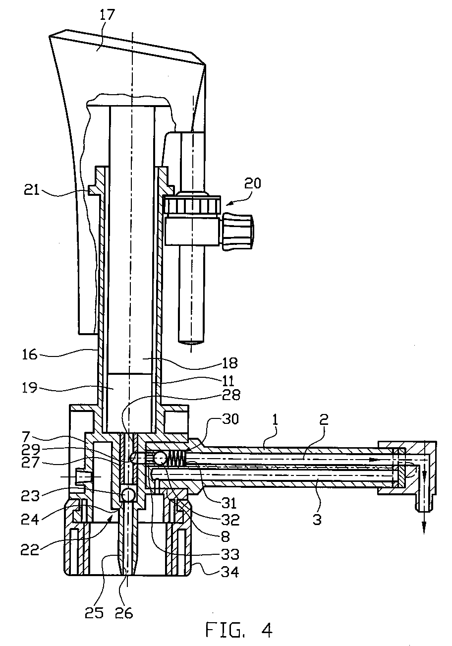
- FIG. 4 shows an axial sectional view through a metering dispenser with a delivery or metering cylinder integrally formed with the valve block 7 11, wherein the feed or metering cylinder 11 in one piece with the valve block 7 formed jacket portion 16 is received.
- the funding or dosing cylinder 11 is a vertical by means of a handle device 17
- the delivery or metering piston is in the embodiment shown here designed as a precision ground piston and limits one in the delivery or dosing cylinder 11 with respect to its volume variable delivery or Dosing chamber 19.
- an adjusting device 20 By means of an adjusting device 20, the permissible stroke of the Delivery or metering piston 18 and thus the maximum volume of the delivery or Dosing room 19 can be set.
- the setting device 20 acts with one Stop 21 together, which is integrally formed with the jacket portion 16 is.
- the stop 21 surrounds an upper end region of the feed or metering cylinder 11 and also forms a reinforcing member for reinforcing the upper Opening of the delivery or metering cylinder 11.
- a container valve 22 is provided, which in the case shown here Embodiment comprises a valve ball 23, which is on a precision valve seat 24 sits, which in the embodiment shown here by a precision-formed Surface portion of the valve body 7 is formed. Below of the container valve 22 extends in a hose pin 25 formed Intake channel 26. The opening stroke of the valve ball 23 is through a bushing element 27 limited by the feed or metering cylinder 11 in the Valve block 7 is pressed.
- the bushing element 27 forms a fluid passage 28, which is the intake duct 26 connects via the container valve 22 to the delivery or metering chamber 19.
- the bushing element 27 is provided with a radial through opening 29 which the fluid passage 28 with one in the base body 1 of the dispensing cannula recorded valve 30 connects. That recorded in the base body 1
- Valve 30 comprises a valve ball pressed into a closed position by means of a spring 31 32 and a valve seat element pressed into the base body 1 of the dispensing cannula 33, which in the embodiment shown here consists of a plastic, Glass or ceramic material is formed.
- Said valve spring 31 is seated in the outflow line formed in the dispensing cannula 2, which are continuous from the valve 30 to its outlet opening extends.
- the outlet opening of the outlet line 2 is immediately adjacent to the inlet opening the return line 3 arranged.
- the one running in the dispensing cannula Return line 3 has essentially the same length as that in the dispensing cannula trained discharge line 2.
- the dispensing cannula is in the valve block 7 pressed in via the press-in pin section 8.
- the press-in pin section 8 is provided with a radial through hole which with a in the Valve block trained fluid path device is connected, via which any fluid conveyed via the return line can get back into the container.
- the valve block 7 is designed here as a skeleton construction and by means of a union nut 34 on a container or, for example, on a supply base can be attached to an automatically operated dosing device.
- a union nut 34 on a container or, for example, on a supply base can be attached to an automatically operated dosing device.
- the dispensing cannula pressed in is advantageous Way also possible, the dispensing cannula, the valve block 7 and the jacket section 16 in one piece, i.e. to train as an integral part.
- a corresponding Integral embodiment advantageously eliminates the valve seat element 33, and a corresponding valve seat surface is through a peripheral wall of the Bushing element 27 formed radially penetrating through hole.
- valve ball 32 and possibly also the valve spring 31 can either be pressed in before of the socket element 27 are used in the valve block 7, or alternatively for this purpose are introduced into the valve block 7 through the outflow line 2.
- the outflow line 2 and the Return line 3 is formed coaxially to one another, preferably the outflow line 2 surrounds the return line 3.
- the invention is not limited to the previously described embodiments limited.
- the dispensing cannula with coaxially arranged channels to insert into the dispensing cannula.
- the pouring element as a cap that can be removed from the dispensing cannula, and for example by connecting the pouring element accordingly either a connection between the discharge line and the return line, or allow fluid discharge from the discharge line.
- the delivery cannula it is curved Outlet area of the outlet line is the outlet opening in the use position a corresponding device points downwards. It is also possible that To close the discharge cannula in the region of its end face 5 and in particular with respect to the outflow line, a fluid discharge through a radial, the peripheral wall drill through the dispensing cannula. With such a Embodiment of the dispensing cannula advantageously forms the in Use position below or, in the case of coaxial channel arrangement, the outside lying fluid path device the outflow line.
- valve in the fluid path leading back into the container, in particular to provide a ball valve that has a fluid outlet, for example due to a change in pressure in the container.
- This valve is more advantageous Way in the area of the inlet mouth of the return line or in arranged the valve block.
- the pouring element is advantageously such trained that this can be brought into a non-use position, in which the two lines formed in the discharge cannula are blocked off from the outside are.
Landscapes
- Physics & Mathematics (AREA)
- Fluid Mechanics (AREA)
- General Physics & Mathematics (AREA)
- Containers And Packaging Bodies Having A Special Means To Remove Contents (AREA)
- Infusion, Injection, And Reservoir Apparatuses (AREA)
- Coating Apparatus (AREA)
- Sampling And Sample Adjustment (AREA)
- Injection Moulding Of Plastics Or The Like (AREA)
- Processing And Handling Of Plastics And Other Materials For Molding In General (AREA)
- Reciprocating Pumps (AREA)
- Feeding, Discharge, Calcimining, Fusing, And Gas-Generation Devices (AREA)
Abstract
Die Erfindung betrifft eine Vorrichtung zur Abgabe einer Flüssigkeit, insbesondere
einen Flüssigkeits-Dosierdispenser, mit einer Fördereinrichtung, mit einem Förderoder
Dosierzylilnder, einem in dem Förder- oder Dosierzylinder hin und her bewegbaren
Förder- oder Dosierkolben zum Fördern oder Dosieren der Flüssigkeit aus
einem Behälter zu einer in einer Ausgabekanüle gebildeten Ausströmleitung mit
einer Einstellvorrichtung zur Hubeinstellung des Förder- oder Dosierkolbens, der in
dem Förder- oder Dosierzylinder einen volumenveränderlichen Förder- oder Dosierraum
begrenzt, wobei die Ausströmleitung eine Austrittsöffnung aufweist, an
der die geförderte Flüssigkeit aus der Ausströmleitung austritt und wobei der Förder-
oder Dosierzylinder mit einem Ventilblock verbunden ist, der einerseits mit einer
Ansaugventileinrichtung zum Ansaugen von Flüssigkeit in den Förder- oder
Dosierzylinder und andererseits mit einem Ausströmventil zum Fördern von Flüssigkeit
aus dem Förder- oder Dosierzylinder in die Ausströmleitung gekoppelt ist.
Außerdem betrifft die Erfindung eine Ausgabekanüle für einen Flüssigkeits-Dosierdispenser,
eine Spritzgießform sowie ein Verfahren zur Herstellung eines
Flüssigkeitsspenders.
Description
Die Erfindung betrifft eine Vorrichtung zur Abgabe einer Flüssigkeit, insbesondere einen Flüssigkeits-Dosierdispenser, mit einer Fördereinrichtung, mit einem Förder- oder Dosierzylilnder, einem in dem Förder- oder Dosierzylinder hin und her bewegbaren Förder- oder Dosierkolben zum Fördern oder Dosieren der Flüssigkeit aus einem Behälter zu einer in einer Ausgabekanüle gebildeten Ausströmleitung mit einer Einstellvorrichtung zur Hubeinstellung des Förder- oder Dosierkolbens, der in dem Förder- oder Dosierzylinder einen volumenveränderlichen Förder- oder Dosierraum begrenzt, wobei die Ausströmleitung eine Austrittsöffnung aufweist, an der die geförderte Flüssigkeit aus der Ausströmleitung austritt und wobei der Förder- oder Dosierzylinder mit einem Ventilblock verbunden ist, der einerseits mit einer Ansaugventileinrichtung zum Ansaugen von Flüssigkeit in den Förder- oder Dosierzylinder und andererseits mit einem Ausströmventil zum Fördern von Flüssigkeit aus dem Förder- oder Dosierzylinder in die Ausströmleitung gekoppelt ist. Außerdem betrifft die Erfindung eine Ausgabekanüle für einen Flüssigkeits-Dosierdispenser, eine Spritzgießform sowie ein Verfahren zur Herstellung eines Flüssigkeitsspenders.The invention relates to a device for dispensing a liquid, in particular a liquid dosing dispenser, with a conveyor, with a conveyor or Dosierzylilnder, a movable back and forth in the feed or dosing cylinder Delivery or dosing pistons for conveying or dosing the liquid a container to an outflow line formed in an outlet cannula an adjusting device for adjusting the stroke of the delivery or metering piston, which in the delivery or dosing cylinder has a volume-adjustable delivery or dosing room limited, wherein the outflow line has an outlet opening which exits the conveyed liquid from the outflow line and the conveying or dosing cylinder is connected to a valve block, on the one hand with a Intake valve device for sucking liquid into the conveyor or Dosing cylinder and on the other hand with an outflow valve for conveying liquid is coupled from the delivery or metering cylinder into the outflow line. The invention also relates to a dispensing cannula for a liquid dispenser, an injection mold and a method for producing a Liquid dispenser.
Aus DE 41 37 351 C2 ist eine herkömmliche Vorrichtung der eingangs genannten Art bekannt, welche einen Ventilblock mit einem Dreiwegehahn aufweist, über welchen wahlweise eine über einen Dosierzylinder aus einem Behälter geförderte Fluidmenge entweder in eine Ausgabekanüle eingespeist wird oder ohne die Ausgabekanüle zu durchlaufen unmittelbar in den Behälter zurückgeführt werden kann.DE 41 37 351 C2 describes a conventional device of the type mentioned at the beginning Kind known, which has a valve block with a three-way valve, via which optionally a quantity of fluid delivered from a container via a dosing cylinder is either fed into an output cannula or without the output cannula to go straight back into the container.
Hinsichtlich dieser herkömmlichen Vorrichtung hat es sich als nachteilig erwiesen, dass selbst nach der Durchführung mehrerer Spülvorgänge, bei welchen das über den Dosierzylinder geförderte Fluid wieder in den Behälter zurückgelangt, sich in einer anschließend dosierten Fluidmenge u.U. stark gealterte Fluidfraktionen befinden, da der Ausgabebereich des Spenders außerhalb des Spülkreislaufes verbleibt. With regard to this conventional device, it has proven to be disadvantageous that even after performing multiple rinses that over the dosing cylinder delivered fluid back into the container, in a subsequently metered amount of fluid may heavily aged fluid fractions, because the dispenser dispensing area remains outside the flushing cycle.
Der Erfindung liegt daher die Aufgabe zugrunde, eine Vorrichtung zur Abgabe einer Flüssigkeit der eingangs genannten Art zu verbessern derart, dass eine vollständige Spülung bzw. Fluidrückführung in den zugehörigen Vorratsbehälter gewährleistet und/oder eine vorteilhafte Herstellbarkeit der Vorrichtung aus Kunststoff erreichbar ist.The invention is therefore based on the object of a device for dispensing a To improve liquid of the type mentioned in such a way that a complete Flushing or fluid return into the associated storage container guaranteed and / or an advantageous manufacturability of the device made of plastic is.
Der Erfindung liegt ferner die Aufgabe zugrunde, eine Ausgabekanüle für einen Flüssigkeitsdosierspender zu schaffen, die eine vollständige Spülung derselben gestattet.The invention is also based on the object of a dispensing cannula for Liquid dispenser to create a full flush of the same allowed.
Schließlich liegt der Erfindung die Aufgabe zugrunde, eine Spritzgießform zur spritzgießtechnischen Herstellung einer solchen Vorrichtung sowie ein Verfahren zur Herstellung eines Flüssigkeitsspenders anzugeben.Finally, the invention has for its object to provide an injection mold Injection molding production of such a device and a method to specify for the manufacture of a liquid dispenser.
Hinsichtlich einer Vorrichtung der eingangs genannten Art wird diese Aufgabe erfindungsgemäß
durch die Merkmale der Ansprüche 5 und 13 bzw. bezüglich des
Aspektes der Herstellbarkeit durch die Merkmale der Ansprüche 1 bis 4, 6 und 7
gelöst.With regard to a device of the type mentioned at the outset, this object is achieved according to the invention
by the features of
Hinsichtlich der Ausgabekanüle wird die vorgenannte Aufgabe erfindungsgemäß
durch die Merkmale des Anspruches 32 gelöst.With regard to the dispensing cannula, the aforementioned object is achieved according to the invention
solved by the features of
Dadurch wird es auf vorteilhafte Weise möglich, im Rahmen eines gegebenenfalls mehrere Pumphübe umfassenden Spülvorganges auch die in der Ausgabekanüle gebildete Ausströmleitung vollständig zu spülen.This makes it possible in an advantageous manner, if necessary several pumping strokes, including the flushing process in the dispensing cannula to completely flush the discharge line formed.
In vorteilhafter Weise ist hierzu im Bereich der Austrittsöffnung der Ausgabekanüle eine Anschlußeinrichtung vorgesehen zum Anschluß der Rücklaufleitung an die Ausströmleitung zum Zurückführen des die Ausströmleitung durchströmenden Fluides in den Behälter. Diese Anschlußeinrichtung kann beispielsweise durch eine an der Ausgabekanüle im Bereich der Austrittsöffnung vorgesehene Kappe gebildet sein. Es ist auch möglich, die Ausgabekanüle im Bereich der Austrittsöffnung mit einer im wesentlichen planen Stirnfläche zu versehen und zwischen der Rücklaufleitung und der Ausströmleitung im Bereich der Austrittsöffnung eine kleine Auskerbung bzw. einen Verbindungskanal vorzusehen, so dass beispielsweise durch Abdecken der genannten Stirnfläche erreicht werden kann, dass das durch die Ausströmleitung geförderte Fluid über die Kerbe oder den Kanal in die Rücklaufleitung zurückströmen kann, und gleichzeitig die Ausströmöffnung dicht verschlossen ist.For this purpose, the dispensing cannula is advantageously in the region of the outlet opening a connection device is provided for connecting the return line to the Outflow line for returning the fluid flowing through the outflow line in the container. This connection device can, for example, by a of the dispensing cannula in the region of the outlet opening his. It is also possible to use the dispensing cannula in the area of the outlet opening to provide an essentially flat end face and between the return line and a small notch in the outlet line in the area of the outlet opening or to provide a connecting channel so that, for example, by Covering the end face mentioned can be achieved by the Outflow line conveyed fluid via the notch or the channel into the return line can flow back, and at the same time the outflow opening is sealed is.
In vorteilhafter Weise sind die Ausströmleitung und die Rücklaufleitung gemeinsam in der vorzugsweise aus einem Kunststoffmaterial, oder bei einer besonders hochwertigen Ausführungsform aus Edelstahl gefertigten Ausgabekanüle ausgebildet. Eine derartige Ausgestaltung der Ausgabekanüle erweist sich insbesondere unter fertigungstechnischen Gesichtspunkten im Hinblick auf eine einfache Montage als besonders vorteilhaft und ermöglicht zudem eine effektive Aussteifung der Ausgabekanüle.The outflow line and the return line are advantageously common in the preferably made of a plastic material, or in a particularly high quality Embodiment made of stainless steel dispensing cannula. Such a configuration of the dispensing cannula proves to be particularly evident under manufacturing aspects with a view to simple assembly as particularly advantageous and also enables effective stiffening of the dispensing cannula.
Die Ausströmleitung und die Rücklaufleitung sind vorzugsweise gleich lang ausgebildet und weisen in vorteilhafter Weise jeweils den gleichen Kanalquerschnitt auf. Insbesondere bei einer Ausführungsform der Ausgabekanüle aus einem Kunststoffmaterial weisen die beiden Leitungen in vorteilhafter Weise jeweils einen kreisförmigen Querschnitt auf und sind bei einer gespritzten Ausführungsform in Längsrichtung jeweils schwach konisch verjüngt ausgebildet. Bei dieser Ausführungsform lassen sich besonders hohe Oberflächenqualitäten hinsichtlich der die beiden Leitungen begrenzenden Leitungsinnenwandungen erreichen. Bei der Herstellung der Ausgabekanüle aus einem Strangpreßmaterial oder auch spanabhebend, beispielsweise aus einem Teflon-Halbzeug, ist die Ausstoßkanküle mit Vorteil von zylindrischer oder prismatischer Gestalt.The outflow line and the return line are preferably of the same length and advantageously each have the same channel cross section. In particular in one embodiment of the dispensing cannula made of a plastic material the two lines advantageously each have a circular shape Cross section on and are in a sprayed embodiment in the longitudinal direction each tapered slightly tapered. In this embodiment can be particularly high surface quality with regard to the two lines reach the inner walls of the pipe. When producing the Dispensing cannula made of an extruded material or also cutting, for example made of a Teflon semi-finished product, the ejection cannula is advantageously cylindrical or prismatic shape.
Die Ausströmleitung und die Rücklaufleitung sind in vorteilhafter Weise derart ausgebildet, dass in einem Austrittsbereich der Ausgabekanüle die Austrittsöffnung der Ausströmleitung einer Eintrittsöffnung der Rücklaufleitung unmittelbar benachbart angeordnet ist. Dadurch wird eine unmittelbare Überbrückung der beiden Leitungen durch eine in der Auschlußeinrichtung ausgebildete Spülverbindung möglich. Mit Vorteil sind dabei die Ausströmleitung und die Rücklaufleitung derart ausgebildet, dass deren Längsachsen zueinander parallel verlaufen. Die Ausgabekanüle ist dabei in vorteilhafter Weise derart gestaltet, dass diese in einer zur Längsachse der Ausströmleitung senkrechten Schnittebene einen kreisförmigen, elliptischen oder vorzugsweise "8"-förmigen Querschnitt aufweist.The outflow line and the return line are advantageously designed in such a way that that in an outlet area of the dispensing cannula the outlet opening of the Outflow line immediately adjacent to an inlet opening of the return line is arranged. This will immediately bridge the two lines possible by a flushing connection formed in the exclusion device. With The outflow line and the return line are of advantage in such a way that that their longitudinal axes run parallel to each other. The dispensing cannula is included advantageously designed in such a way that this is in a to the longitudinal axis of the Exhaust line vertical section plane a circular, elliptical or preferably has an "8" -shaped cross section.
Eine im Hinblick auf eine unter ergonomischen Gesichtspunkten besonders vorteilhafte Ausführungsform der Erfindung ist dadurch gegeben, dass die Anschlußeinrichtung durch ein Ausgußelement gebildet ist, das in einem, der Ausströmöffnung benachbarten Bereich der Ausgabekanüle angeordnet ist, wobei das Ausgußelement in eine Überbrückungsposition bringbar ist, in welcher die Ausströmleitung mit der Rückführleitung verbunden ist. Das Ausgußelement ist in vorteilhafter Weise mit einer Griffeinrichtung versehen zum manuellen Umschalten zwischen einer Überbrückungsposition, einer Abgabeposition und ggf. auch einer Schließposition, in welcher die Austrittsöffnung der Ausgabekanüle verschlossen ist. Die genannte Griffeinrichtung ist in vorteilhafter Weise einstückig mit dem beispielsweise aus einem Kunststoffmaterial gebildeten Ausgußelement ausgebildet.One that is particularly advantageous in terms of ergonomics Embodiment of the invention is given in that the connection device is formed by a pouring element, which in one, the outflow opening adjacent area of the dispensing cannula is arranged, wherein the pouring element can be brought into a bridging position in which the outflow line the return line is connected. The pouring element is advantageous provided with a handle device for manual switching between a bridging position, a delivery position and possibly also a closed position, in which the outlet opening of the dispensing cannula is closed. The said Handle device is advantageously in one piece with, for example, from one Plastic material formed pouring element.
Das Ausgußelement ist in vorteilhafter Weise schwenkbewegbar oder verschiebbar an der Ausgabekanüle befestigt. Die Schwenk- oder Verschiebeachse verläuft hierbei im wesentlichen in Längsrichtung der Ausgabekanüle. Das Ausgußelement ist in vorteilhafter Weise verschlußkappenartig ausgebildet und auf einer Außenumfangsfläche der Ausgabekanüle schwenkbewegbar bzw. verschiebbar gelagert.The pouring element is advantageously pivotable or displaceable attached to the dispensing cannula. The swivel or sliding axis runs here essentially in the longitudinal direction of the dispensing cannula. The pouring element is advantageously formed like a cap and on an outer peripheral surface the dispensing cannula is pivotally mounted or slidably mounted.
Bei einer bevorzugten Ausführungsform der Vorrichtung ist die Ausgabekanüle an einem Ventilblock angeschlossen, wobei in dem Ventilblock ein Fluidzufuhrkanal und ein Fluidrücklaufkanal ausgebildet sind, die entsprechend mit der Ausströmleitung und der Rücklaufleitung verbunden sind. Dieser Ventilblock ist dabei in vorteilhafter Weise aus einem Kunststoffmaterial durch Spritz-Formen oder spanend hergestellt. Der in dem Ventilblock gebildete Fluidzufuhrkanal und der ebenfalls in dem Ventilblock gebildete Fluidrücklaufkanal können dabei auf fertigungstechnisch besonders vorteilhafte Weise durch zylindrische Kernelemente gebildet werden, die in den zur Bildung des Ventilblocks in einem Formwerkzeug gebildeten Formraum eindringen und nach Aushärten des Kunststoffmateriales aus diesem abgezogen werden können. In a preferred embodiment of the device, the dispensing cannula is on connected to a valve block, a fluid supply channel in the valve block and a fluid return channel are formed, which correspond to the outflow line and the return line are connected. This valve block is more advantageous Made from a plastic material by injection molding or machining. The fluid supply channel formed in the valve block and also in the Fluid return channel formed in the valve block can be of special manufacturing technology advantageously formed by cylindrical core elements, which in the mold space formed to form the valve block in a mold penetrate and after curing the plastic material is removed from this can be.
Im Hinblick auf einen einfachen Aufbau eines Formwerkzeuges zur Bildung des Ventilblockes wird die Ausgabekanüle vorzugsweise als separates Bauteil ausgebildet und erst im Rahmen eines Montageschrittes in den Ventilblock eingepreßt. Dadurch wird es zum einen auf vorteilhafte Weise möglich, unterschiedliche Ausgabekanülen und ggf. auch unterschiedliche Ventilblöcke bedarfsgerecht miteinander zu kombinieren. Die Verwendung einer Preß-Verbindungseinrichtung erlaubt eine besonders fest haftende, hochdichte Befestigung der Ausgabekanüle an dem Ventilblock. Alternativ dazu kann die Ausgabekanüle auch über eine Gewindeeinrichtung an dem Ventilblock angebracht werden. Hierzu ist vorzugsweise die Ausgabekanüle oder eine Überwurfmutter mit einem Gewindeabschnitt versehen.With regard to a simple structure of a mold for forming the Valve block, the dispensing cannula is preferably designed as a separate component and only pressed into the valve block as part of an assembly step. On the one hand, this advantageously makes it possible to use different dispensing cannulas and possibly also different valve blocks with each other as required to combine. The use of a press connector allows a particularly tight, high-density attachment of the dispensing cannula to the Valve block. As an alternative to this, the dispensing cannula can also have a threaded device be attached to the valve block. For this purpose, the dispensing cannula is preferably used or provide a union nut with a threaded section.
Der Ventilblock kann auch aus einem Block-Material, beispielsweise durch spanabhebende Bearbeitung gebildet sein. Im Hinblick auf eine hohe chemische Beständigkeit besteht der Ventilblock vorzugsweise aus einem Teflon-, Polypropylen- (PP), Polyethylen- (PE) oder Polyamid-Werkstoff.The valve block can also be made of a block material, for example by machining Processing be formed. With a view to high chemical resistance the valve block preferably consists of a Teflon, polypropylene (PP), polyethylene (PE) or polyamide material.
Eine besonders stabile und im Bereich des Dosierzylinderfußes hochdichte Ausführungsform der Vorrichtung ist dadurch gegeben, dass der Förder- bzw. Dosierzylinder einstückig mit dem Ventilblock ausgebildet ist. Der Förder- bzw. Dosierzylinder und der Ventilblock und ggf. auch die Ausgabekanüle können dabei im Rahmen eines einzigen Kunststoffeinspritzvorganges im Inneren eines entsprechenden Formwerkzeuges gebildet werden, so dass nach Öffnen des Formwerkzeuges eine wenigstens aus Förder- bzw. Dosierzylinder und Ventilblock bestehende Baueinheit dem Formwerkzeug entnommen werden kann. Das Formwerkzeug ist hierzu in vorteilhafter Weise wenigstens zweiteilig ausgebildet, wobei eine zwischen den beiden Formteilen verlaufende Trennfläche vorzugsweise im wesentlichen parallel zu einer Ebene verläuft, die eine Mittelachse des Förder- bzw. Dosierzylinders enthält.A particularly stable and high-density embodiment in the area of the metering cylinder base the device is given in that the feed or metering cylinder is integrally formed with the valve block. The feed or dosing cylinder and the valve block and possibly also the dispensing cannula can be in the frame a single plastic injection process inside a corresponding one Forming tool are formed so that after opening the mold a at least consisting of delivery or metering cylinder and valve block can be taken from the mold. The mold is in advantageously formed at least in two parts, one between the separating surface extending in two molded parts preferably essentially parallel to a plane that contains a central axis of the delivery or metering cylinder.
Eine bei der integralen Ausbildung von Förder- bzw. Dosierzylinder und Ventilblock vorteilhafte Ausführungsform der Erfindung ist dadurch gegeben, dass der Förder- bzw. Dosierzylinder einen aus einem Glas-, Keramik-, thermoplastischen oder duroplastischen Kunststoffmaterial gebildeten Zylinder-Einsatz umfaßt, der in einem einstückig mit dem Ventilblock ausgebildeten Mantelabschnitt aufgenommen, insbesondere eingespritzt ist. Dadurch wird es auf vorteilhafte Weise möglich, eine extrem hohe Dichtwirkung zwischen der Innenwandung des Förder- bzw. Dosierzylinders und einem darin leichtgängig hin- und hergehend bewegbaren Förder- bzw. Dosierkolben sicherzustellen. Aufgrund des vorzugsweise einstückig mit dem Ventilblock ausgebildeten Mantelabschnittes ist für den Zylinder-Einsatz eine effektive Verstärkung und ein effektiver Splitter-Schutz gegeben.One in the integral design of the delivery or dosing cylinder and valve block An advantageous embodiment of the invention is given in that the conveyor or dosing cylinder one from a glass, ceramic, thermoplastic or thermosetting Plastic material formed cylinder insert, which in a recorded in one piece with the valve block, in particular is injected. This makes it possible in an advantageous manner extremely high sealing effect between the inner wall of the feed or dosing cylinder and a conveying or Ensure dosing pistons. Because of the preferably in one piece with the valve block trained jacket section is effective for cylinder use Reinforcement and effective splinter protection.
Eine im Hinblick auf eine hohe Materialersparnis vorteilhafte Ausführungsform der Erfindung ist dadurch gegeben, dass der Ventilblock als Skelettkonstruktion mit beabstandeten Stegen ausgebildet ist. Diese zueinander beabstandeten Stege verlaufen dabei in vorteilhafter Weise im wesentlichen parallel zu einer Mittelachse des Förder- bzw. Dosierzylinders. Die einzelnen Stege können zur weiteren Aussteifung des Ventilblockes durch weitere, fachwerkartig angeordnete Querverbindungsstege ausgesteift sein. Um eine besonders stabile Befestigung der Ausgabekanüle an einem derartigen, als Skelettkonstruktion ausgebildeten Ventilblock zu erreichen, ist in vorteilhafter Weise eine Aufnahmeausnehmung zur Aufnahme eines Fußabschnittes der Ausgabekanüle derart angeordnet, dass diese einen der sich axial erstreckenden Stege radial durchsetzt. Eine Mittelachse der vorzugsweise zylindrischen Aufnahmeausnehmung verläuft dabei in vorteilhafter Weise in einer entsprechenden Mittelebene des sich axial erstreckenden Versteifungssteges. Die Aufnahmeausnehmung ist dabei in vorteilhafter Weise in einem topfartigen Wandungsabschnitt aufgenommen. Dieser topfartige Wandungsabschnitt kann zusätzlich durch weitere, beispielsweise radiale Querversteifungsstege noch weiter ausgesteift werden.An advantageous embodiment in terms of high material savings Invention is given in that the valve block with a skeleton construction spaced webs is formed. These spaced apart webs advantageously run essentially parallel to a central axis of the delivery or dosing cylinder. The individual webs can be used for further bracing of the valve block by means of further cross-connection webs arranged in the manner of a truss be stiffened. For a particularly stable attachment of the dispensing cannula to such a valve block designed as a skeleton construction achieve, is advantageously a receiving recess for receiving a Base section of the dispensing cannula arranged such that this one of the extending axially extending webs radially. A central axis of preferably cylindrical receiving recess advantageously runs in one corresponding central plane of the axially extending stiffening web. The receiving recess is advantageously in a pot-like manner Wall section added. This pot-like wall section can additionally by further, for example radial transverse stiffening webs be braced.
Um eine positionsgenaue Befestigung der Ausgabekanüle an dem Ventilblock zu ermöglichen, ist in vorteilhafter Weise durch entsprechende Abschnitte des Ventilblockes und der Ausgabekanüle eine Positioniereinrichtung gebildet, durch die die Befestigungsposition der Ausgabekanüle an dem Ventilblock eindeutig festgelegt ist. Diese Positioniereinrichtung kann dabei entweder einen kanülenseitig ausgebildeten Eingriffsabschnitt aufweisen, der mit einem ventilblockseitig ausgebildeten Eingriffsgegenabschnitt in Eingriff bringbar ist, oder einen an dem Ventilblock im Bereich der Aufnahmeausnehmung ausgebildeten Eingriffsabschnitt aufweisen, der mit einem kanülenseitig ausgebildeten Eingriffsgegenabschnitt in Eingriff bringbar ist.In order to fix the dispensing cannula to the valve block in a precise position enable, is advantageously by corresponding sections of the valve block and the dispensing cannula is formed by a positioning device through which the Fixing position of the dispensing cannula on the valve block is clearly defined is. This positioning device can either be a cannula side Have engagement section, which is formed with a valve block side Engagement section can be brought into engagement, or one on the valve block in the Have area of the receiving recess formed engagement portion, the can be brought into engagement with a mating engagement section formed on the cannula side is.
Um eine besonders hohe Dichtwirkung und um einen besonders festen Sitz der Ausgabekanüle in dem Ventilblock sicherzustellen, sind an einem Befestigungsabschnitt der Ausgabekanüle vorzugsweise mehrere Dichtlamellen ausgebildet, die unter hoher Flächenpressung mit einem entsprechenden Innen-Umfangsabschnitt einer in dem Ventilblock gebildeten Aufnahmeausnehmung in Kontakt treten.For a particularly high sealing effect and for a particularly tight fit of the Dispensing cannulas in the valve block are secured to a mounting section the delivery cannula preferably formed a plurality of sealing lamellae under high surface pressure with a corresponding inner peripheral section come into contact with a receiving recess formed in the valve block.
Hinsichtlich der Spritzgießform und des Verfahrens zur Herstellung eines Flüssigkeitsspenders wird die vorgenannte Aufgabe erfindungsgemäß durch die Merkmale der Ansprüche 43 und 44 gelöst.With regard to the injection mold and the process for producing a liquid dispenser the aforementioned object is inventively by the features of claims 43 and 44 solved.
Vorteilhafte Weiterbildungen sind jeweils Gegenstand der zugehörigen Unteransprüche.Advantageous further developments are the subject of the associated subclaims.
Die Erfindung wird nachstehend anhand von Ausführungsbeispielen und zugehörigen Zeichnungen näher erläutert. In diesen zeigen:
- Fig.1
- eine in Integralbauweise gebildete Ausgabekanüle mit parallel nebeneinander verlaufenden Ausström- bzw. Rücklaufleitungen;
- Fig.2a
- einen Axialschnitt durch eine in einen Sockelbereich eines Dosier-Dispensers eingesetzte Ausgabekanüle, wobei die Ausgabekanüle im Bereich ihrer Austrittsöffnung mit einem Ausgußelement versehen ist, das sich hier in einer Abgabeposition befindet;
- Fig.2b
- eine Axialschnittansicht durch die gleiche Ausgabekanüle sowie durch das gleiche Ausgußelement, wobei das Ausgußelement sich jedoch hier in einer Spül-Position befindet;
- Fig.3a
- eine Detail-Axialschnittansicht und eine vereinfachte, zugehörige Seitenansicht des Ausgußelementes in Abgabeposition,
- Fig.3b
- eine Detail-Axialschnittansicht und eine vereinfachte, zugehörige Seitenansicht des Ausgußelementes in Spülposition,
- Fig.4
- eine Axialschnittansicht durch einen Dosier-Dispenser mit integral ausgebildetem Förder- bzw. Dosierzylinder und einer Ausabekanüle mit integral eingeformter Rücklaufleitung.
- Fig.1
- an integral delivery cannula with parallel outflow or return lines;
- 2a
- an axial section through an outlet cannula inserted into a base region of a metering dispenser, the outlet cannula being provided in the region of its outlet opening with a pouring element, which is located here in a dispensing position;
- 2b
- an axial sectional view through the same dispensing cannula and through the same pouring element, but the pouring element is here in a rinsing position;
- 3a
- 2 shows a detailed axial sectional view and a simplified, associated side view of the pouring element in the dispensing position,
- 3b
- 2 shows a detailed axial sectional view and a simplified, associated side view of the pouring element in the rinsing position,
- Figure 4
- an axial sectional view through a metering dispenser with integrally formed delivery or metering cylinder and an output cannula with integrally molded return line.
Die in Fig.1 dargestellte Ausgabekanüle umfaßt einen Grundkörper 1, der vorzugsweise
aus einem Kunststoffmaterial gefertigt ist. In dem Grundkörper 1 sind
sowohl eine Ausströmleitung 2 als auch eine Rücklaufleitung 3 ausgebildet. Die
Ausströmleitung 2 und die Rücklaufleitung 3 sind durch einen Trennwandabschnitt
4, der einstückig mit dem Grundkörper 1 ausgebildet ist, voneinander getrennt.
Sowohl die Ausströmleitung 2 als auch die Rücklaufleitung 3 weisen einen kreisförmigen
Querschnitt auf und münden bei der hier dargestellten Ausführungsform
in eine plan ausgebildete Stirnfläche 5.The dispensing cannula shown in FIG. 1 comprises a base body 1, which is preferably
is made of a plastic material. In the base body 1 are
both an
Auf einer der Stirnfläche 5 abgewandten Seite des Grundkörpers 1 ist die Ausgabekanüle
mit einem Befestigungsabschnitt 6 versehen, über welchen die Ausgabekanüle
an einem hier durch das Bezugszeichen 7 bezeichneten Ventilblock anbringbar
ist. Der Befestigungsabschnitt 6 umfaßt bei der hier dargestellten Ausführungsform
einen im wesentlichen zylindrischen Einpreßzapfenabschnitt 8, der in
enger Passung, abdichtend in eine entsprechend ausgebildete Paßbohrung des
Ventilblocks 7 eingepreßt ist. Alternativ zu der dargestellten Ausführungsform des
Befestigungsabschnittes 6 ist es auch möglich, die Ausgabekanüle integral mit dem
Ventilblock 7 auszubilden oder beispielsweise über eine Gewindeeinrichtung mit
dem Ventilblock 7 zu verbinden. Die Gewindeeinrichtung ist mit Vorteil derart gestaltet,
dass im festgezogenen Zustand zwischen den Gewindeflanken kein Hohlraum
verbleibt. Dies kann insbesondere durch ein schwach konisches Gewinde
erreicht werden.The dispensing cannula is on a side of the base body 1 facing away from the
In dem hier nur abschnittsweise dargestellten Ventilblock 7 sind ein Fluidzufuhrkanal
9 sowie ein Fluidrücklaufkanal 10 ausgebildet. In the valve block 7 shown here only in sections, there is a
Der Fluidzufuhrkanal 9 umfaßt ein hier nicht dargestelltes Saugventil und mündet
über eine stirnseitig in dem Befestigungsabschnitt 6 ausgebildete Durchgangsöffnung
in die Ausströmleitung 2. Die in dem Grundkörper 1 ausgebildete Rücklaufleitung
3 steht über eine, den Befestigungs- bzw. Einpreßzapfenabschnitt 8 oder Gewindezapfenabschnitt
radial durchsetzende Durchgangsbohrung mit dem Fluidrücklaufkanal
10 in Verbindung. Der Fluidrücklaufkanal 10 ist hier als im wesentlichen
geradliniger Kanal ausgebildet und erstreckt sich schwach geneigt von einem
unteren Bereich des Ventilblockes 7 zu dem Befestigungsabschnitt 8. Durch die
hohe Flächenpressung zwischen dem Befestigungsabschnitt 8 und der Innenwandung
der in dem Ventilblock 7 ausgebildeten Befestigungsbohrung wird eine hohe
Dichtigkeit des Übergangsbereiches zwischen der Rücklaufleitung 3 und dem in
dem Ventilblock 7 ausgebildeten Fluidrücklaufkanal 10 erreicht.The
Bei der hier dargestellten Ausführungsform sind die Ausströmleitung 2 und die
Rücklaufleitung 3 in nebeneinanderliegender Weise ausgebildet. Es ist auch möglich,
die Ausströmleitung 2 und die Rücklaufleitung 3 zueinander koaxial auszubilden,
so dass eine der beiden Leitungen durch einen entsprechend dimensionierten
Ringraum gebildet ist. Die Rücklaufleitung 3 erstreckt sich durchgängig ununterbrochen
von der Austrittsöffnung der Ausströmleitung 2 zurück zu dem Ventilblock 7.In the embodiment shown here, the
Eine vollständige Spülung der Ausströmleitung 2 kann beispielsweise dadurch erreicht
werden, dass auf den Grundkörper 1 im Bereich der Stirnfläche 5 ein Kappenelement
aufgesetzt wird, das eine Verbindung zwischen der Ausströmleitung 2
und der Rücklaufleitung 3 herstellt.A complete flushing of the
Anstelle einer derartigen Überbrückungseinrichtung kann ein Ausgußelement 12
verwendet werden, wie dies nachfolgend in Verbindung mit den Fig.2a und 2b beschrieben
wird.Instead of such a bridging device, a pouring
Die Darstellungen gemäß den Fig.2a und 2b sind abgesehen von jeweils unterschiedlichen
Schaltstellungen des Ausgußelementes 12 identisch.The representations according to FIGS. 2a and 2b are different in each case
Switch positions of the pouring
Abweichend von der Darstellung gemäß Fig.1 ist der zur Aufnahme der Ausgabekanüle vorgesehene Ventilblock 7 mit einem durch das Bezugszeichen 11 bezeichneten (nur teilweise dargestellten) Förder- bzw. Dosierzylinder hier vollständig gezeigt. Die hier dargestellte Ausgabekanüle ist an dem Ventilblock 7 in gleicher Weise befestigt, wie dies vorab bereits in Verbindung mit Fig.1 erläutert wurde.1 is the one for receiving the dispensing cannula provided valve block 7 with a designated by the reference numeral 11 (only partially shown) delivery or dosing cylinder shown completely here. The dispensing cannula shown here is on the valve block 7 in the same way attached, as previously explained in connection with Fig.1.
An ihrem, dem Ventilblock 7 abgewandten Ende ist die Ausgabekanüle mit einem
Ausgußelement 12, das schwenkbewegbar oder verschiebbar an dem Grundkörper
1 angebracht ist, versehen. In der hier dargestellten Position befindet sich das
Ausgußelement in einer Abgabestellung und gestattet die Abströmung eines durch
den Förder- bzw. Dosierzylinder zunächst über eine hier nicht dargestellte Ansaugleitung
angesaugten Fluides über den Fluidzufuhrkanal 9 und die Ausströmleitung
2. Um eine besonders leichtgängige Bewegung des Ausgußelementes 12 relativ
zu dem Grundkörper 1 zu ermöglichen, und um ferner eine zuverlässige Abdichtung
der Eintrittsmündung der Rücklaufleitung 3 zu ermöglichen, sind zwischen
dem Ausgußelement 12 und dem Grundkörper 1 zwei Gleitscheiben 13, 14 vorgesehen,
die über das Ausgußelement 12 und eine hier nicht näher dargestellte Eingriffsstruktur
zwischen dem Ausgußelement 12 und dem Grundkörper 1 in enger
Anlage an der in Fig.1 mit dem Bezugszeichen 5 bezeichneten Stirnfläche gehalten
sind.At its end facing away from the valve block 7, the dispensing cannula is provided with a
Pouring
Die Gleitscheiben 13, 14 sind vorzugsweise aus einem Glas-, Kunststoff- oder Keramikmaterial
gebildet und mit Durchgangsöffnungen versehen, die je nach Position
des Ausgußelementes 12 in Deckung bringbar sind.The sliding
Das Ausgußelement 12 ist bei der hier dargestellten Ausführungsform um eine parallel
zur Mittelachse des Grundkörpers 1 der Ausgabekanüle verlaufende
Schwenkachse schwenkbewegbar. In dem Ausgußelement 12 ist eine kurze Umlenkbohrung
15 oder Umlenkkanal ausgebildet, über welche das aus der Ausströmleitung
2 austretende Fluid umgelenkt wird.The pouring
Bei der in Fig.2b dargestellten Funktionsposition des Ausgußelementes 12 überbrückt
dieses die Ausströmleitung 2 und die Rücklaufleitung 3 und ermöglicht dadurch
den vereinfacht durch Pfeile angedeuteten Fluidstrom von dem Förder- bzw.
Dosierzylinder 11 zurück in einen hier nicht dargestellten Behälter bzw. vergleichbare
Sammeleinrichtung. Dadurch wird es beispielsweise möglich, eine größere
Fluidmenge über den Förder- bzw. Dosierzylinder 11 und durch die Ausgabekanüle
hindurch zu fördern, wodurch sichergestellt ist, dass sich in der Ausgabekanüle
kein mittlerweile gealtertes oder beispielsweise durch Trocknung hinsichtlich seiner
Konzentration verändertes Fluid befindet. Der Aufbau und die Funktionsweise des
vorangehend beschriebenen Ausgußelementes 12 werden nachfolgend in Verbindung
mit den Figuren 3a und 3b noch näher erläutert.Bridged in the functional position of the pouring
Bei der Prinzipdarstellung gem. Fig.3a befindet sich das Ausgußelement 12 in der
bereits in Verbindung mit Fig.2a erläuterten Schaltposition. Eine in dem Ausgußelement
12 gebildete Umlenkbohrung 15 bzw. der Umlenkkanal weist dabei in Abgabeposition
in vertikaler Richtung nach unten. In dieser Schaltposition des Ausgußelementes
12 geraten die in den Gleitscheiben 13 und 14 gebildeten Durchgangsbohrungen
derart in Deckung, dass das zugeführte Fluid aus der Ausströmleitung
2 abfließen kann. Wird nunmehr das Ausgußelement 12 aus der in Fig.3a
dargestellten Schaltposition in die in Fig.3b dargestellte Schaltposition geschwenkt,
so wird die in der Ausgabekanüle gebildete Ausströmleitung 2 mit der Rücklaufleitung
3 verbunden, wodurch ein vollständiger Fluid-Austausch des in der Ausströmleitung
2 zunächst befindlichen Fluides möglich wird.In the principle representation acc. 3a is the pouring
Die Darstellung gemäß Fig.4 zeigt eine Axialschnittansicht durch einen Dosierdispenser
mit einem integral mit dem Ventilblock 7 ausgebildeten Förder- bzw. Dosierzylinder
11, wobei der Förder- bzw. Dosierzylinder 11 in einem einstückig mit
dem Ventilblock 7 ausgebildeten Mantelabschnitt 16 aufgenommen ist. In dem Förder-
bzw. Dosierzylinder 11 ist ein mittels einer Handgriffeinrichtung 17 in vertikaler
Richtung auf- und abwärts bewegbarer Förder- bzw. Dosierkolben 18 aufgenommen.
Der Förder- bzw. Dosierkolben ist bei der hier dargestellten Ausführungsform
als Präzisionsgeschliffener Kolben ausgebildet und begrenzt einen in dem Förder-
bzw. Dosierzylinder 11 hinsichtlich seines Volumens veränderbaren Förder- bzw.
Dosierraum 19. Mittels einer Einstelleinrichtung 20 kann der zulässige Hub des
Förder- bzw. Dosierkolbens 18 und damit das Maximal-Volumen des Förder- bzw.
Dosierraumes 19 eingestellt werden. Die Einstelleinrichtung 20 wirkt dabei mit einem
Anschlag 21 zusammen, der einstückig mit dem Mantelabschnitt 16 ausgebildet
ist. Der Anschlag 21 umgibt einen oberen Endbereich des Förder- bzw. Dosierzylinders
11 und bildet zudem ein Verstärkungsglied zur Verstärkung der oberen
Öffnung des Förder- bzw. Dosierzylinders 11.The illustration according to FIG. 4 shows an axial sectional view through a metering dispenser
with a delivery or metering cylinder integrally formed with the valve block 7
11, wherein the feed or
In dem Ventilblock 7 ist ein Behälterventil 22 vorgesehen, das bei der hier dargestellten
Ausführungsform eine Ventilkugel 23 umfaßt, die auf einem Präzisionsventilsitz
24 aufsitzt, der bei der hier dargestellten Ausführungsform durch einen präzisionsgeformten
Oberflächenabschnitt des Ventilkörpers 7 gebildet ist. Unterhalb
des Behälterventiles 22 erstreckt sich ein in einem Schlauchzapfen 25 gebildeter
Ansaugkanal 26. Der Öffnungshub der Ventilkugel 23 wird durch ein Buchsenelement
27 begrenzt, das durch den Förder- bzw. Dosierzylinder 11 hindurch in den
Ventilblock 7 eingepreßt ist.In the valve block 7, a
Das Buchsenelement 27 bildet einen Fluiddurchgangsweg 28, der den Ansaugkanal
26 über das Behälterventil 22 mit dem Förder- bzw. Dosierraum 19 verbindet.
Das Buchsenelement 27 ist mit einer radialen Durchgangsöffnung 29 versehen, die
den Fluiddurchgangsweg 28 mit einem in dem Grundkörper 1 der Ausgabekanüle
aufgenommenen Ventil 30 verbindet. Das in dem Grundkörper 1 aufgenommene
Ventil 30 umfaßt eine mittels einer Feder 31 in eine Schließstellung gedrängte Ventilkugel
32 und ein in den Grundkörper 1 der Ausgabekanüle eingepreßtes Ventilsitzelement
33, das bei der hier dargestellten Ausführungsform aus einem Kunststoff-,
Glas- bzw. Keramikmaterial gebildet ist.The bushing element 27 forms a
Die genannte Ventilfeder 31 sitzt in der, in der Ausgabekanüle gebildeten Ausströmleitung
2, die sich durchgängig von dem Ventil 30 bis zu ihrer Austrittsöffnung
erstreckt.Said
Die Austrittsöffnung der Ausströmleitung 2 ist unmittelbar benachbart der Eintrittsöffnung
der Rücklaufleitung 3 angeordnet. Die in der Ausgabekanüle verlaufende
Rücklaufleitung 3 weist im wesentlichen die gleiche Länge auf wie die in der Ausgabekanüle
ausgebildete Ausströmleitung 2. Die Ausgabekanüle ist in den Ventilblock
7 über den Einpreßzapfenabschnitt 8 eingepreßt. Der Einpreßzapfenabschnitt
8 ist mit einer radialen Durchgangsbohrung versehen, die mit einer in dem
Ventilblock ausgebildeten Fluidwegeinrichtung verbunden ist, über welche etwaig
über die Rücklaufleitung gefördertes Fluid in den Behälter zurückgelangen kann. The outlet opening of the
Der Ventilblock 7 ist hier als Skelettkonstruktion ausgebildet und mittels einer Überwurfmutter
34 an einem Behälter oder beispielsweise auch an einem Versorgungssockel
einer automatisch betätigten Dosiervorrichtung anbringbar. Alternativ zu der
hier dargestellten Ausführungsform mit eingepreßter Ausgabekanüle ist es in vorteilhafter
Weise auch möglich, die Ausgabekanüle, den Ventilblock 7 und den Mantelabschnitt
16 einstückig, d.h. als Integralteil auszubilden. Bei einer entsprechenden
Integral-Ausführungsform entfällt in vorteilhafter Weise das Ventilsitzelement 33, und
eine entsprechende Ventilsitzfläche wird durch eine Umfangswandung der, das
Buchsenelement 27 radial durchsetzenden Durchgangsbohrung gebildet. Die Ventilkugel
32 und ggf. auch die Ventilfeder 31 können dabei entweder vor Einpressen
des Buchsenelementes 27 in den Ventilblock 7 eingesetzt werden, oder alternativ
dazu durch die Ausströmleitung 2 hindurch in den Ventilblock 7 eingeführt werden.
Insbesondere bei dieser Integralausführungsform sind die Ausströmleitung 2 und die
Rücklaufleitung 3 koaxial zueinander ausgebildet, wobei vorzugsweise die Ausströmleitung
2 die Rücklaufleitung 3 umgibt.The valve block 7 is designed here as a skeleton construction and by means of a union nut
34 on a container or, for example, on a supply base
can be attached to an automatically operated dosing device. Alternatively to that
The embodiment shown here with the dispensing cannula pressed in is advantageous
Way also possible, the dispensing cannula, the valve block 7 and the
Die Erfindung ist nicht auf die vorangehend beschriebenen Ausführungsformen beschränkt. Beispielsweise ist es auch möglich, insbesondere bei einer Ausführungsform der Ausgabekanüle mit koaxial angeordneten Kanälen das Ausgußelement in die Ausgabekanüle einzustecken. Es ist auch möglich, das Ausgußelement als von der Ausgabekanüle abnehmbare Kappe auszugestalten, und beispielsweise durch entsprechendes Aufstecken des Ausgußelementes entweder eine Verbindung zwischen der Ausströmleitung und der Rücklaufleitung zu erzeugen, oder eine Fluidableitung aus der Ausströmleitung zuzulassen.The invention is not limited to the previously described embodiments limited. For example, it is also possible, in particular in one embodiment the dispensing cannula with coaxially arranged channels to insert into the dispensing cannula. It is also possible to use the pouring element as a cap that can be removed from the dispensing cannula, and for example by connecting the pouring element accordingly either a connection between the discharge line and the return line, or allow fluid discharge from the discharge line.
Es ist auch möglich, die Ausgabekanüle gekrümmt auszubilden, so dass die im
Austrittsbereich der Auströmleitung befindliche Austrittsöffnung in Gebrauchsposition
einer entsprechenden Vorrichtung nach unten weist. Es ist auch möglich, die
Ausgabekanüle im Bereich ihrer Stirnfläche 5 zu verschließen und insbesondere
bezüglich der Ausströmleitung eine Fluidableitung durch eine radiale, die Umfangswandung
der Ausgabekanüle durchsetzende Bohrung vorzunehmen. Bei einer derartigen
Ausführungsform der Ausgabekanüle bildet in vorteilhafter Weise die in
Gebrauchsposition unten liegende bzw. bei koaxialer Kanalanordnung die außen
liegende Fluidwegeinrichtung die Ausströmleitung.It is also possible to design the delivery cannula so that it is curved
Outlet area of the outlet line is the outlet opening in the use position
a corresponding device points downwards. It is also possible that
To close the discharge cannula in the region of its
Es ist auch möglich, in dem, in den Behälter zurückführenden Fluidweg ein Ventil, insbesondere ein Kugelventil vorzusehen, das einen Fluid-Austritt, beispielsweise aufgrund einer Druckänderung in dem Behälter, verhindert. Dieses Ventil ist in vorteilhafter Weise im Bereich der Eintrittsmündung der Rücklaufleitung oder auch in dem Ventilblock angeordnet. Das Ausgußelement ist in vorteilhafter Weise derart ausgebildet, dass dieses in eine Nicht-Gebrauchsstellung bringbar ist, in welcher die beiden in der Ausgabekanüle ausgebildeten Leitungen nach außen hin abgesperrt sind.It is also possible to have a valve in the fluid path leading back into the container, in particular to provide a ball valve that has a fluid outlet, for example due to a change in pressure in the container. This valve is more advantageous Way in the area of the inlet mouth of the return line or in arranged the valve block. The pouring element is advantageously such trained that this can be brought into a non-use position, in which the two lines formed in the discharge cannula are blocked off from the outside are.
Claims (45)
Applications Claiming Priority (3)
| Application Number | Priority Date | Filing Date | Title |
|---|---|---|---|
| DE19807647A DE19807647C5 (en) | 1998-02-23 | 1998-02-23 | Device for dispensing a fluid and dispensing cannula for this purpose |
| DE19807647 | 1998-02-23 | ||
| EP99102395A EP0937967B1 (en) | 1998-02-23 | 1999-02-08 | Fluid dispenser and associated dispensing tubes |
Related Parent Applications (3)
| Application Number | Title | Priority Date | Filing Date |
|---|---|---|---|
| EP99102395.3 Division | 1999-02-08 | ||
| EP99102395A Division-Into EP0937967B1 (en) | 1998-02-23 | 1999-02-08 | Fluid dispenser and associated dispensing tubes |
| EP99102395A Division EP0937967B1 (en) | 1998-02-23 | 1999-02-08 | Fluid dispenser and associated dispensing tubes |
Publications (3)
| Publication Number | Publication Date |
|---|---|
| EP1434037A2 true EP1434037A2 (en) | 2004-06-30 |
| EP1434037A3 EP1434037A3 (en) | 2006-01-04 |
| EP1434037B1 EP1434037B1 (en) | 2010-10-27 |
Family
ID=7858698
Family Applications (2)
| Application Number | Title | Priority Date | Filing Date |
|---|---|---|---|
| EP99102395A Expired - Lifetime EP0937967B1 (en) | 1998-02-23 | 1999-02-08 | Fluid dispenser and associated dispensing tubes |
| EP04008332A Expired - Lifetime EP1434037B1 (en) | 1998-02-23 | 1999-02-08 | Fluid dispenser and associated dispensing tubes |
Family Applications Before (1)
| Application Number | Title | Priority Date | Filing Date |
|---|---|---|---|
| EP99102395A Expired - Lifetime EP0937967B1 (en) | 1998-02-23 | 1999-02-08 | Fluid dispenser and associated dispensing tubes |
Country Status (4)
| Country | Link |
|---|---|
| EP (2) | EP0937967B1 (en) |
| AT (1) | ATE286240T1 (en) |
| DE (3) | DE19861333B4 (en) |
| ES (1) | ES2236974T3 (en) |
Cited By (3)
| Publication number | Priority date | Publication date | Assignee | Title |
|---|---|---|---|---|
| US7198176B2 (en) | 2002-07-31 | 2007-04-03 | Poulten & Graf Gmbh | Liquid dispenser, hollow dispensing needle kit system for said liquid dispenser, and hollow dispensing needle |
| WO2012159028A1 (en) * | 2011-05-18 | 2012-11-22 | Nigel Kelly | Fluid dispenser |
| WO2017088793A1 (en) * | 2015-11-25 | 2017-06-01 | King's Flair Marketing Limited | Fluid dispenser with reflux mechanism |
Family Cites Families (7)
| Publication number | Priority date | Publication date | Assignee | Title |
|---|---|---|---|---|
| JPS601383Y2 (en) * | 1979-04-19 | 1985-01-16 | 株式会社ニチリヨー | dispenser |
| DE3208436C2 (en) * | 1982-02-22 | 1985-09-26 | Glasgerätebau Hirschmann, 7101 Eberstadt | Bottle dispenser |
| DE9218204U1 (en) * | 1991-11-13 | 1993-09-16 | Walu-Apparatetechnik GmbH, 97877 Wertheim | Bottle dispenser |
| DE4137351C2 (en) * | 1991-11-13 | 1997-01-16 | Walu Apparatetechnik Gmbh | Bottle dispenser |
| DE4334974C2 (en) * | 1993-10-14 | 2002-11-14 | Poulten & Graf Gmbh | Device for dosing liquids, in particular bottle-top dispenser and method for producing such a device |
| FR2767073B1 (en) * | 1997-08-05 | 1999-10-22 | Sedat | LIQUID DISTRIBUTION HEAD AND FLUID CONDITIONING COMPRISING IT |
| DE19754558B4 (en) * | 1997-12-09 | 2005-07-07 | Hirschmann Laborgeräte GmbH & Co. KG | bottle top |
-
1998
- 1998-02-23 DE DE19861333A patent/DE19861333B4/en not_active Expired - Fee Related
-
1999
- 1999-02-08 EP EP99102395A patent/EP0937967B1/en not_active Expired - Lifetime
- 1999-02-08 DE DE59915216T patent/DE59915216D1/en not_active Expired - Lifetime
- 1999-02-08 DE DE59911345T patent/DE59911345D1/en not_active Expired - Lifetime
- 1999-02-08 EP EP04008332A patent/EP1434037B1/en not_active Expired - Lifetime
- 1999-02-08 ES ES99102395T patent/ES2236974T3/en not_active Expired - Lifetime
- 1999-02-08 AT AT99102395T patent/ATE286240T1/en active
Cited By (5)
| Publication number | Priority date | Publication date | Assignee | Title |
|---|---|---|---|---|
| US7198176B2 (en) | 2002-07-31 | 2007-04-03 | Poulten & Graf Gmbh | Liquid dispenser, hollow dispensing needle kit system for said liquid dispenser, and hollow dispensing needle |
| WO2012159028A1 (en) * | 2011-05-18 | 2012-11-22 | Nigel Kelly | Fluid dispenser |
| US10751214B2 (en) | 2011-05-18 | 2020-08-25 | Nigel Kelly | Fluid dispenser |
| WO2017088793A1 (en) * | 2015-11-25 | 2017-06-01 | King's Flair Marketing Limited | Fluid dispenser with reflux mechanism |
| CN108367856B (en) * | 2015-11-25 | 2019-11-26 | 科劲市场管理有限公司 | Fluid distributor with reflux mechanism |
Also Published As
| Publication number | Publication date |
|---|---|
| DE59915216D1 (en) | 2010-12-09 |
| EP0937967B1 (en) | 2004-12-29 |
| ES2236974T3 (en) | 2005-07-16 |
| EP0937967A1 (en) | 1999-08-25 |
| DE59911345D1 (en) | 2005-02-03 |
| DE19861333B4 (en) | 2005-08-18 |
| ATE286240T1 (en) | 2005-01-15 |
| EP1434037B1 (en) | 2010-10-27 |
| EP1434037A3 (en) | 2006-01-04 |
Similar Documents
| Publication | Publication Date | Title |
|---|---|---|
| EP0790079B1 (en) | method for producing a dispenser or the like | |
| DE102009011900B3 (en) | Apparatus for producing plastic parts interspersed with reinforcing fibers | |
| DE2502971B2 (en) | Device for ejecting a mixture of liquids | |
| EP0519967B1 (en) | Applicator head for media | |
| EP1670380A1 (en) | Water jet and handpiece for a water jet | |
| DE1704791B2 (en) | DEVICE FOR THE PRODUCTION OF CROSS-SECTION RING-SHAPED BODIES FROM THERMOPLASTIC PLASTIC | |
| EP0285551A2 (en) | Injection nozzle for thermoplastic material | |
| EP0303590A2 (en) | Device for spraying the outside of a core, especially one of an electric conductor | |
| DE3534901A1 (en) | HIGH PRESSURE MIXING HEAD | |
| DE102010012325A1 (en) | Jet regulator or the like sanitary outlet element and method and injection molding tool for its production | |
| DE19807647C5 (en) | Device for dispensing a fluid and dispensing cannula for this purpose | |
| EP1434037A2 (en) | Fluid dispenser and associated dispensing tubes | |
| WO2019121704A1 (en) | Arrangement of nozzle units for a wiper arm, wiper arm and use of a nozzle unit | |
| DE102009024278B4 (en) | filling | |
| DE19715709B4 (en) | Liquid dispenser, conveying and dosing cylinder, conveying and dosing device and method for producing a liquid dispenser | |
| EP1525436B1 (en) | Liquid dispenser, hollow dispensing needle kit system for said liquid dispenser, and hollow dispensing needle | |
| DE69724616T2 (en) | LIQUID DISPENSER AND ITS PRODUCTION PROCESS | |
| WO2003016020A1 (en) | Injection unit with a device for mixing and dosing plastic melt and additives | |
| DE3000444A1 (en) | Accumulator type extrusion head for blow-moulding parison - comprises head body, plate having hole the same dia as head body, rod of servo-cylinder, mandrel core and plunger | |
| DE19644979A1 (en) | Medical or dental handpiece | |
| DE19722612C1 (en) | Multi=component injection moulding process and nozzle | |
| DE202006013373U1 (en) | Perfume atomizer has spray opening, port and air supply duct assembled and installed directly in horizontal through opening in main body with centred positioning and roller balls for clog-free operation | |
| AT501156A4 (en) | EXTRUSION NOZZLE FOR EXTRUDING HOLLOW PROFILES | |
| EP0040695B1 (en) | Backflow seal for screw injection moulding machines | |
| DE2621810C3 (en) | Foam gun for generating a multi-component foam in the low-pressure process |
Legal Events
| Date | Code | Title | Description |
|---|---|---|---|
| PUAI | Public reference made under article 153(3) epc to a published international application that has entered the european phase |
Free format text: ORIGINAL CODE: 0009012 |
|
| AC | Divisional application: reference to earlier application |
Ref document number: 0937967 Country of ref document: EP Kind code of ref document: P |
|
| AK | Designated contracting states |
Kind code of ref document: A2 Designated state(s): AT BE CH DE ES FI FR GB IT LI NL |
|
| PUAL | Search report despatched |
Free format text: ORIGINAL CODE: 0009013 |
|
| AK | Designated contracting states |
Kind code of ref document: A3 Designated state(s): AT BE CH DE ES FI FR GB IT LI NL |
|
| 17P | Request for examination filed |
Effective date: 20060330 |
|
| AKX | Designation fees paid |
Designated state(s): DE FR GB IT |
|
| 17Q | First examination report despatched |
Effective date: 20070625 |
|
| RAP1 | Party data changed (applicant data changed or rights of an application transferred) |
Owner name: BRAND GMBH + CO KG |
|
| GRAP | Despatch of communication of intention to grant a patent |
Free format text: ORIGINAL CODE: EPIDOSNIGR1 |
|
| GRAS | Grant fee paid |
Free format text: ORIGINAL CODE: EPIDOSNIGR3 |
|
| GRAA | (expected) grant |
Free format text: ORIGINAL CODE: 0009210 |
|
| AC | Divisional application: reference to earlier application |
Ref document number: 0937967 Country of ref document: EP Kind code of ref document: P |
|
| AK | Designated contracting states |
Kind code of ref document: B1 Designated state(s): DE FR GB IT |
|
| REG | Reference to a national code |
Ref country code: GB Ref legal event code: FG4D Free format text: NOT ENGLISH |
|
| REF | Corresponds to: |
Ref document number: 59915216 Country of ref document: DE Date of ref document: 20101209 Kind code of ref document: P |
|
| PLBE | No opposition filed within time limit |
Free format text: ORIGINAL CODE: 0009261 |
|
| STAA | Information on the status of an ep patent application or granted ep patent |
Free format text: STATUS: NO OPPOSITION FILED WITHIN TIME LIMIT |
|
| 26N | No opposition filed |
Effective date: 20110728 |
|
| REG | Reference to a national code |
Ref country code: DE Ref legal event code: R097 Ref document number: 59915216 Country of ref document: DE Effective date: 20110728 |
|
| PG25 | Lapsed in a contracting state [announced via postgrant information from national office to epo] |
Ref country code: IT Free format text: LAPSE BECAUSE OF FAILURE TO SUBMIT A TRANSLATION OF THE DESCRIPTION OR TO PAY THE FEE WITHIN THE PRESCRIBED TIME-LIMIT Effective date: 20101027 |
|
| REG | Reference to a national code |
Ref country code: DE Ref legal event code: R082 Ref document number: 59915216 Country of ref document: DE Representative=s name: VON ROHR PATENTANWAELTE PARTNERSCHAFT MBB, DE |
|
| PGFP | Annual fee paid to national office [announced via postgrant information from national office to epo] |
Ref country code: FR Payment date: 20140219 Year of fee payment: 16 |
|
| REG | Reference to a national code |
Ref country code: FR Ref legal event code: ST Effective date: 20151030 |
|
| PG25 | Lapsed in a contracting state [announced via postgrant information from national office to epo] |
Ref country code: FR Free format text: LAPSE BECAUSE OF NON-PAYMENT OF DUE FEES Effective date: 20150302 |
|
| PGFP | Annual fee paid to national office [announced via postgrant information from national office to epo] |
Ref country code: DE Payment date: 20180219 Year of fee payment: 20 Ref country code: GB Payment date: 20180216 Year of fee payment: 20 |
|
| REG | Reference to a national code |
Ref country code: DE Ref legal event code: R071 Ref document number: 59915216 Country of ref document: DE |
|
| REG | Reference to a national code |
Ref country code: GB Ref legal event code: PE20 Expiry date: 20190207 |
|
| PG25 | Lapsed in a contracting state [announced via postgrant information from national office to epo] |
Ref country code: GB Free format text: LAPSE BECAUSE OF EXPIRATION OF PROTECTION Effective date: 20190207 |