EP1434037A2 - Distributeur de fluide et tubes distributeurs associés - Google Patents
Distributeur de fluide et tubes distributeurs associés Download PDFInfo
- Publication number
- EP1434037A2 EP1434037A2 EP04008332A EP04008332A EP1434037A2 EP 1434037 A2 EP1434037 A2 EP 1434037A2 EP 04008332 A EP04008332 A EP 04008332A EP 04008332 A EP04008332 A EP 04008332A EP 1434037 A2 EP1434037 A2 EP 1434037A2
- Authority
- EP
- European Patent Office
- Prior art keywords
- delivery
- metering
- liquid
- conveying
- dispensing
- Prior art date
- Legal status (The legal status is an assumption and is not a legal conclusion. Google has not performed a legal analysis and makes no representation as to the accuracy of the status listed.)
- Granted
Links
Images


Classifications
-
- B—PERFORMING OPERATIONS; TRANSPORTING
- B05—SPRAYING OR ATOMISING IN GENERAL; APPLYING FLUENT MATERIALS TO SURFACES, IN GENERAL
- B05B—SPRAYING APPARATUS; ATOMISING APPARATUS; NOZZLES
- B05B11/00—Single-unit hand-held apparatus in which flow of contents is produced by the muscular force of the operator at the moment of use
- B05B11/01—Single-unit hand-held apparatus in which flow of contents is produced by the muscular force of the operator at the moment of use characterised by the means producing the flow
- B05B11/10—Pump arrangements for transferring the contents from the container to a pump chamber by a sucking effect and forcing the contents out through the dispensing nozzle
- B05B11/1001—Piston pumps
- B05B11/1015—Piston pumps actuated without substantial movement of the nozzle in the direction of the pressure stroke
-
- B—PERFORMING OPERATIONS; TRANSPORTING
- B05—SPRAYING OR ATOMISING IN GENERAL; APPLYING FLUENT MATERIALS TO SURFACES, IN GENERAL
- B05B—SPRAYING APPARATUS; ATOMISING APPARATUS; NOZZLES
- B05B11/00—Single-unit hand-held apparatus in which flow of contents is produced by the muscular force of the operator at the moment of use
- B05B11/0005—Components or details
-
- B—PERFORMING OPERATIONS; TRANSPORTING
- B05—SPRAYING OR ATOMISING IN GENERAL; APPLYING FLUENT MATERIALS TO SURFACES, IN GENERAL
- B05B—SPRAYING APPARATUS; ATOMISING APPARATUS; NOZZLES
- B05B1/00—Nozzles, spray heads or other outlets, with or without auxiliary devices such as valves, heating means
- B05B1/30—Nozzles, spray heads or other outlets, with or without auxiliary devices such as valves, heating means designed to control volume of flow, e.g. with adjustable passages
- B05B1/3093—Recirculation valves, i.e. the valve element opens a passage to the nozzle and simultaneously closes at least partially a return passage the feeding means
-
- B—PERFORMING OPERATIONS; TRANSPORTING
- B05—SPRAYING OR ATOMISING IN GENERAL; APPLYING FLUENT MATERIALS TO SURFACES, IN GENERAL
- B05B—SPRAYING APPARATUS; ATOMISING APPARATUS; NOZZLES
- B05B11/00—Single-unit hand-held apparatus in which flow of contents is produced by the muscular force of the operator at the moment of use
- B05B11/01—Single-unit hand-held apparatus in which flow of contents is produced by the muscular force of the operator at the moment of use characterised by the means producing the flow
- B05B11/10—Pump arrangements for transferring the contents from the container to a pump chamber by a sucking effect and forcing the contents out through the dispensing nozzle
- B05B11/1001—Piston pumps
- B05B11/1005—Piston pumps with means for adjusting or modifying pump stroke
- B05B11/1007—Piston pumps with means for adjusting or modifying pump stroke by adjusting or modifying the pump end-of-sucking-stroke position
-
- B—PERFORMING OPERATIONS; TRANSPORTING
- B05—SPRAYING OR ATOMISING IN GENERAL; APPLYING FLUENT MATERIALS TO SURFACES, IN GENERAL
- B05B—SPRAYING APPARATUS; ATOMISING APPARATUS; NOZZLES
- B05B15/00—Details of spraying plant or spraying apparatus not otherwise provided for; Accessories
- B05B15/50—Arrangements for cleaning; Arrangements for preventing deposits, drying-out or blockage; Arrangements for detecting improper discharge caused by the presence of foreign matter
-
- G—PHYSICS
- G01—MEASURING; TESTING
- G01F—MEASURING VOLUME, VOLUME FLOW, MASS FLOW OR LIQUID LEVEL; METERING BY VOLUME
- G01F11/00—Apparatus requiring external operation adapted at each repeated and identical operation to measure and separate a predetermined volume of fluid or fluent solid material from a supply or container, without regard to weight, and to deliver it
- G01F11/02—Apparatus requiring external operation adapted at each repeated and identical operation to measure and separate a predetermined volume of fluid or fluent solid material from a supply or container, without regard to weight, and to deliver it with measuring chambers which expand or contract during measurement
- G01F11/021—Apparatus requiring external operation adapted at each repeated and identical operation to measure and separate a predetermined volume of fluid or fluent solid material from a supply or container, without regard to weight, and to deliver it with measuring chambers which expand or contract during measurement of the piston type
- G01F11/025—Apparatus requiring external operation adapted at each repeated and identical operation to measure and separate a predetermined volume of fluid or fluent solid material from a supply or container, without regard to weight, and to deliver it with measuring chambers which expand or contract during measurement of the piston type with manually operated pistons
- G01F11/028—Apparatus requiring external operation adapted at each repeated and identical operation to measure and separate a predetermined volume of fluid or fluent solid material from a supply or container, without regard to weight, and to deliver it with measuring chambers which expand or contract during measurement of the piston type with manually operated pistons the dosing device being provided with a dip tube and fitted to a container, e.g. to a bottleneck
-
- G—PHYSICS
- G01—MEASURING; TESTING
- G01F—MEASURING VOLUME, VOLUME FLOW, MASS FLOW OR LIQUID LEVEL; METERING BY VOLUME
- G01F15/00—Details of, or accessories for, apparatus of groups G01F1/00 - G01F13/00 insofar as such details or appliances are not adapted to particular types of such apparatus
- G01F15/12—Cleaning arrangements; Filters
Definitions
- the invention relates to a device for dispensing a liquid, in particular a liquid dosing dispenser, with a conveyor, with a conveyor or Dosierzylilnder, a movable back and forth in the feed or dosing cylinder Delivery or dosing pistons for conveying or dosing the liquid a container to an outflow line formed in an outlet cannula an adjusting device for adjusting the stroke of the delivery or metering piston, which in the delivery or dosing cylinder has a volume-adjustable delivery or dosing room limited, wherein the outflow line has an outlet opening which exits the conveyed liquid from the outflow line and the conveying or dosing cylinder is connected to a valve block, on the one hand with a Intake valve device for sucking liquid into the conveyor or Dosing cylinder and on the other hand with an outflow valve for conveying liquid is coupled from the delivery or metering cylinder into the outflow line.
- the invention also relates to a dispensing cannula for
- DE 41 37 351 C2 describes a conventional device of the type mentioned at the beginning kind known, which has a valve block with a three-way valve, via which optionally a quantity of fluid delivered from a container via a dosing cylinder is either fed into an output cannula or without the output cannula to go straight back into the container.
- the invention is therefore based on the object of a device for dispensing a To improve liquid of the type mentioned in such a way that a complete Flushing or fluid return into the associated storage container guaranteed and / or an advantageous manufacturability of the device made of plastic is.
- the invention is also based on the object of a dispensing cannula for Liquid dispenser to create a full flush of the same allowed.
- the invention has for its object to provide an injection mold Injection molding production of such a device and a method to specify for the manufacture of a liquid dispenser.
- the dispensing cannula is advantageously in the region of the outlet opening a connection device is provided for connecting the return line to the Outflow line for returning the fluid flowing through the outflow line in the container.
- This connection device can, for example, by a of the dispensing cannula in the region of the outlet opening his. It is also possible to use the dispensing cannula in the area of the outlet opening to provide an essentially flat end face and between the return line and a small notch in the outlet line in the area of the outlet opening or to provide a connecting channel so that, for example, by Covering the end face mentioned can be achieved by the Outflow line conveyed fluid via the notch or the channel into the return line can flow back, and at the same time the outflow opening is sealed is.
- the outflow line and the return line are advantageously common in the preferably made of a plastic material, or in a particularly high quality Embodiment made of stainless steel dispensing cannula.
- Such a configuration of the dispensing cannula proves to be particularly evident under manufacturing aspects with a view to simple assembly as particularly advantageous and also enables effective stiffening of the dispensing cannula.
- the outflow line and the return line are preferably of the same length and advantageously each have the same channel cross section.
- the two lines advantageously each have a circular shape Cross section on and are in a sprayed embodiment in the longitudinal direction each tapered slightly tapered.
- the ejection cannula is advantageously cylindrical or prismatic shape.
- the outflow line and the return line are advantageously designed in such a way that that in an outlet area of the dispensing cannula the outlet opening of the Outflow line immediately adjacent to an inlet opening of the return line is arranged. This will immediately bridge the two lines possible by a flushing connection formed in the exclusion device.
- the outflow line and the return line are of advantage in such a way that that their longitudinal axes run parallel to each other.
- the dispensing cannula is included advantageously designed in such a way that this is in a to the longitudinal axis of the Exhaust line vertical section plane a circular, elliptical or preferably has an "8" -shaped cross section.
- connection device is formed by a pouring element, which in one, the outflow opening adjacent area of the dispensing cannula is arranged, wherein the pouring element can be brought into a bridging position in which the outflow line the return line is connected.
- the pouring element is advantageous provided with a handle device for manual switching between a bridging position, a delivery position and possibly also a closed position, in which the outlet opening of the dispensing cannula is closed.
- the said Handle device is advantageously in one piece with, for example, from one Plastic material formed pouring element.
- the pouring element is advantageously pivotable or displaceable attached to the dispensing cannula.
- the swivel or sliding axis runs here essentially in the longitudinal direction of the dispensing cannula.
- the pouring element is advantageously formed like a cap and on an outer peripheral surface the dispensing cannula is pivotally mounted or slidably mounted.
- the dispensing cannula is on connected to a valve block, a fluid supply channel in the valve block and a fluid return channel are formed, which correspond to the outflow line and the return line are connected.
- This valve block is more advantageous Made from a plastic material by injection molding or machining.
- the fluid supply channel formed in the valve block and also in the Fluid return channel formed in the valve block can be of special manufacturing technology advantageously formed by cylindrical core elements, which in the mold space formed to form the valve block in a mold penetrate and after curing the plastic material is removed from this can be.
- the dispensing cannula is preferably designed as a separate component and only pressed into the valve block as part of an assembly step.
- this advantageously makes it possible to use different dispensing cannulas and possibly also different valve blocks with each other as required to combine.
- the use of a press connector allows a particularly tight, high-density attachment of the dispensing cannula to the Valve block.
- the dispensing cannula can also have a threaded device be attached to the valve block.
- the dispensing cannula is preferably used or provide a union nut with a threaded section.
- the valve block can also be made of a block material, for example by machining Processing be formed. With a view to high chemical resistance the valve block preferably consists of a Teflon, polypropylene (PP), polyethylene (PE) or polyamide material.
- a particularly stable and high-density embodiment in the area of the metering cylinder base the device is given in that the feed or metering cylinder is integrally formed with the valve block.
- the feed or dosing cylinder and the valve block and possibly also the dispensing cannula can be in the frame a single plastic injection process inside a corresponding one Forming tool are formed so that after opening the mold a at least consisting of delivery or metering cylinder and valve block can be taken from the mold.
- the mold is in advantageously formed at least in two parts, one between the separating surface extending in two molded parts preferably essentially parallel to a plane that contains a central axis of the delivery or metering cylinder.
- valve block with a skeleton construction spaced webs is formed. These spaced apart webs advantageously run essentially parallel to a central axis of the delivery or dosing cylinder.
- the individual webs can be used for further bracing of the valve block by means of further cross-connection webs arranged in the manner of a truss be stiffened.
- a receiving recess for receiving a Base section of the dispensing cannula arranged such that this one of the extending axially extending webs radially.
- a central axis of preferably cylindrical receiving recess advantageously runs in one corresponding central plane of the axially extending stiffening web.
- the receiving recess is advantageously in a pot-like manner Wall section added.
- This pot-like wall section can additionally by further, for example radial transverse stiffening webs be braced.
- a positioning device through which the Fixing position of the dispensing cannula on the valve block is clearly defined is.
- This positioning device can either be a cannula side Have engagement section, which is formed with a valve block side Engagement section can be brought into engagement, or one on the valve block in the Have area of the receiving recess formed engagement portion, the can be brought into engagement with a mating engagement section formed on the cannula side is.
- the delivery cannula preferably formed a plurality of sealing lamellae under high surface pressure with a corresponding inner peripheral section come into contact with a receiving recess formed in the valve block.
- the dispensing cannula shown in FIG. 1 comprises a base body 1, which is preferably is made of a plastic material.
- a base body 1 In the base body 1 are both an outflow line 2 and a return line 3 are formed.
- the Outflow line 2 and the return line 3 are through a partition section 4, which is formed in one piece with the base body 1, separated from one another.
- Both the outflow line 2 and the return line 3 have a circular shape Cross-section and open in the embodiment shown here in a flat end face 5.
- the dispensing cannula is on a side of the base body 1 facing away from the end face 5 provided with a fastening section 6, via which the dispensing cannula can be attached to a valve block designated here by reference numeral 7 is.
- the fastening section 6 comprises in the embodiment shown here a substantially cylindrical press-in pin section 8, which in tight fit, sealing in a correspondingly designed fitting hole of the Valve block 7 is pressed.
- the dispensing cannula it is also possible for the dispensing cannula to be integral with the Form valve block 7 or, for example, with a threaded device to connect the valve block 7.
- the thread device is advantageously designed such that that there is no cavity between the thread flanks when tightened remains. This can be due to a weakly tapered thread can be achieved.
- valve block 7 shown here only in sections, there is a fluid supply channel 9 and a fluid return channel 10 are formed.
- the fluid supply channel 9 comprises a suction valve (not shown here) and opens out via a through opening formed on the end face in the fastening section 6 into the outflow line 2.
- the return line formed in the base body 1 3 stands over one, the fastening or press-in pin section 8 or threaded pin section radially penetrating through hole with the fluid return channel 10 in connection.
- the fluid return channel 10 is here as essential straight channel and extends slightly inclined from one lower region of the valve block 7 to the fastening section 8. Through the high surface pressure between the fastening section 8 and the inner wall the mounting hole formed in the valve block 7 becomes high Tightness of the transition area between the return line 3 and the in the valve block 7 formed fluid return channel 10 reached.
- the outflow line 2 and the Return line 3 formed in a side-by-side manner. It is also possible, to form the outflow line 2 and the return line 3 coaxially with one another, so that one of the two lines is dimensioned accordingly Annulus is formed.
- the return line 3 extends continuously without interruption from the outlet opening of the outflow line 2 back to the valve block 7.
- a complete flushing of the outflow line 2 can thereby be achieved, for example be that a cap element on the base body 1 in the region of the end face 5 is placed that a connection between the outflow line 2 and the return line 3.
- a pouring element 12 can be used, as described below in connection with Figures 2a and 2b becomes.
- FIGS. 2a and 2b are different in each case Switch positions of the pouring element 12 are identical.
- valve block 7 is the one for receiving the dispensing cannula provided valve block 7 with a designated by the reference numeral 11 (only partially shown) delivery or dosing cylinder shown completely here.
- the dispensing cannula shown here is on the valve block 7 in the same way attached, as previously explained in connection with Fig.1.
- the dispensing cannula is provided with a Pouring element 12, which is pivotable or displaceable on the base body 1 is attached, provided. This is in the position shown here Pouring element in a dispensing position and allows the outflow through the delivery or dosing cylinder first via a suction line, not shown here sucked in fluid via the fluid supply channel 9 and the outflow line 2.
- Relative to a particularly smooth movement of the pouring element 12 to the base body 1, and also to provide a reliable seal to allow the inlet mouth of the return line 3 are between the pouring element 12 and the base body 1 are provided with two sliding disks 13, 14, the via the pouring element 12 and an engagement structure not shown here between the pouring element 12 and the base body 1 in closer 1 on the end face designated by the reference number 5 are.
- the sliding disks 13, 14 are preferably made of a glass, plastic or ceramic material formed and provided with through openings depending on the position of the pouring element 12 can be brought into congruence.
- the pouring element 12 is parallel to one in the embodiment shown here extending to the central axis of the base body 1 of the dispensing cannula Swivel axis can be swiveled. There is a short deflection hole in the pouring element 12 15 or deflection channel, via which that from the discharge line 2 escaping fluid is diverted.
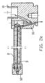
- FIG. 4 shows an axial sectional view through a metering dispenser with a delivery or metering cylinder integrally formed with the valve block 7 11, wherein the feed or metering cylinder 11 in one piece with the valve block 7 formed jacket portion 16 is received.
- the funding or dosing cylinder 11 is a vertical by means of a handle device 17
- the delivery or metering piston is in the embodiment shown here designed as a precision ground piston and limits one in the delivery or dosing cylinder 11 with respect to its volume variable delivery or Dosing chamber 19.
- an adjusting device 20 By means of an adjusting device 20, the permissible stroke of the Delivery or metering piston 18 and thus the maximum volume of the delivery or Dosing room 19 can be set.
- the setting device 20 acts with one Stop 21 together, which is integrally formed with the jacket portion 16 is.
- the stop 21 surrounds an upper end region of the feed or metering cylinder 11 and also forms a reinforcing member for reinforcing the upper Opening of the delivery or metering cylinder 11.
- a container valve 22 is provided, which in the case shown here Embodiment comprises a valve ball 23, which is on a precision valve seat 24 sits, which in the embodiment shown here by a precision-formed Surface portion of the valve body 7 is formed. Below of the container valve 22 extends in a hose pin 25 formed Intake channel 26. The opening stroke of the valve ball 23 is through a bushing element 27 limited by the feed or metering cylinder 11 in the Valve block 7 is pressed.
- the bushing element 27 forms a fluid passage 28, which is the intake duct 26 connects via the container valve 22 to the delivery or metering chamber 19.
- the bushing element 27 is provided with a radial through opening 29 which the fluid passage 28 with one in the base body 1 of the dispensing cannula recorded valve 30 connects. That recorded in the base body 1
- Valve 30 comprises a valve ball pressed into a closed position by means of a spring 31 32 and a valve seat element pressed into the base body 1 of the dispensing cannula 33, which in the embodiment shown here consists of a plastic, Glass or ceramic material is formed.
- Said valve spring 31 is seated in the outflow line formed in the dispensing cannula 2, which are continuous from the valve 30 to its outlet opening extends.
- the outlet opening of the outlet line 2 is immediately adjacent to the inlet opening the return line 3 arranged.
- the one running in the dispensing cannula Return line 3 has essentially the same length as that in the dispensing cannula trained discharge line 2.
- the dispensing cannula is in the valve block 7 pressed in via the press-in pin section 8.
- the press-in pin section 8 is provided with a radial through hole which with a in the Valve block trained fluid path device is connected, via which any fluid conveyed via the return line can get back into the container.
- the valve block 7 is designed here as a skeleton construction and by means of a union nut 34 on a container or, for example, on a supply base can be attached to an automatically operated dosing device.
- a union nut 34 on a container or, for example, on a supply base can be attached to an automatically operated dosing device.
- the dispensing cannula pressed in is advantageous Way also possible, the dispensing cannula, the valve block 7 and the jacket section 16 in one piece, i.e. to train as an integral part.
- a corresponding Integral embodiment advantageously eliminates the valve seat element 33, and a corresponding valve seat surface is through a peripheral wall of the Bushing element 27 formed radially penetrating through hole.
- valve ball 32 and possibly also the valve spring 31 can either be pressed in before of the socket element 27 are used in the valve block 7, or alternatively for this purpose are introduced into the valve block 7 through the outflow line 2.
- the outflow line 2 and the Return line 3 is formed coaxially to one another, preferably the outflow line 2 surrounds the return line 3.
- the invention is not limited to the previously described embodiments limited.
- the dispensing cannula with coaxially arranged channels to insert into the dispensing cannula.
- the pouring element as a cap that can be removed from the dispensing cannula, and for example by connecting the pouring element accordingly either a connection between the discharge line and the return line, or allow fluid discharge from the discharge line.
- the delivery cannula it is curved Outlet area of the outlet line is the outlet opening in the use position a corresponding device points downwards. It is also possible that To close the discharge cannula in the region of its end face 5 and in particular with respect to the outflow line, a fluid discharge through a radial, the peripheral wall drill through the dispensing cannula. With such a Embodiment of the dispensing cannula advantageously forms the in Use position below or, in the case of coaxial channel arrangement, the outside lying fluid path device the outflow line.
- valve in the fluid path leading back into the container, in particular to provide a ball valve that has a fluid outlet, for example due to a change in pressure in the container.
- This valve is more advantageous Way in the area of the inlet mouth of the return line or in arranged the valve block.
- the pouring element is advantageously such trained that this can be brought into a non-use position, in which the two lines formed in the discharge cannula are blocked off from the outside are.
Landscapes
- Physics & Mathematics (AREA)
- Fluid Mechanics (AREA)
- General Physics & Mathematics (AREA)
- Containers And Packaging Bodies Having A Special Means To Remove Contents (AREA)
- Infusion, Injection, And Reservoir Apparatuses (AREA)
- Coating Apparatus (AREA)
- Sampling And Sample Adjustment (AREA)
- Injection Moulding Of Plastics Or The Like (AREA)
- Processing And Handling Of Plastics And Other Materials For Molding In General (AREA)
- Reciprocating Pumps (AREA)
- Feeding, Discharge, Calcimining, Fusing, And Gas-Generation Devices (AREA)
Applications Claiming Priority (3)
| Application Number | Priority Date | Filing Date | Title |
|---|---|---|---|
| DE19807647A DE19807647C5 (de) | 1998-02-23 | 1998-02-23 | Vorrichtung zur Abgabe eines Fluides sowie Ausgabekanüle hierfür |
| DE19807647 | 1998-02-23 | ||
| EP99102395A EP0937967B1 (fr) | 1998-02-23 | 1999-02-08 | Distributeur de fluide et tubes distributeurs associés |
Related Parent Applications (3)
| Application Number | Title | Priority Date | Filing Date |
|---|---|---|---|
| EP99102395.3 Division | 1999-02-08 | ||
| EP99102395A Division-Into EP0937967B1 (fr) | 1998-02-23 | 1999-02-08 | Distributeur de fluide et tubes distributeurs associés |
| EP99102395A Division EP0937967B1 (fr) | 1998-02-23 | 1999-02-08 | Distributeur de fluide et tubes distributeurs associés |
Publications (3)
| Publication Number | Publication Date |
|---|---|
| EP1434037A2 true EP1434037A2 (fr) | 2004-06-30 |
| EP1434037A3 EP1434037A3 (fr) | 2006-01-04 |
| EP1434037B1 EP1434037B1 (fr) | 2010-10-27 |
Family
ID=7858698
Family Applications (2)
| Application Number | Title | Priority Date | Filing Date |
|---|---|---|---|
| EP99102395A Expired - Lifetime EP0937967B1 (fr) | 1998-02-23 | 1999-02-08 | Distributeur de fluide et tubes distributeurs associés |
| EP04008332A Expired - Lifetime EP1434037B1 (fr) | 1998-02-23 | 1999-02-08 | Distributeur de fluide et tubes distributeurs associés |
Family Applications Before (1)
| Application Number | Title | Priority Date | Filing Date |
|---|---|---|---|
| EP99102395A Expired - Lifetime EP0937967B1 (fr) | 1998-02-23 | 1999-02-08 | Distributeur de fluide et tubes distributeurs associés |
Country Status (4)
| Country | Link |
|---|---|
| EP (2) | EP0937967B1 (fr) |
| AT (1) | ATE286240T1 (fr) |
| DE (3) | DE19861333B4 (fr) |
| ES (1) | ES2236974T3 (fr) |
Cited By (3)
| Publication number | Priority date | Publication date | Assignee | Title |
|---|---|---|---|---|
| US7198176B2 (en) | 2002-07-31 | 2007-04-03 | Poulten & Graf Gmbh | Liquid dispenser, hollow dispensing needle kit system for said liquid dispenser, and hollow dispensing needle |
| WO2012159028A1 (fr) * | 2011-05-18 | 2012-11-22 | Nigel Kelly | Distributeur de fluide |
| WO2017088793A1 (fr) * | 2015-11-25 | 2017-06-01 | King's Flair Marketing Limited | Distributeur de fluide avec mécanisme de reflux |
Family Cites Families (7)
| Publication number | Priority date | Publication date | Assignee | Title |
|---|---|---|---|---|
| JPS601383Y2 (ja) * | 1979-04-19 | 1985-01-16 | 株式会社ニチリヨー | デイスペンサ |
| DE3208436C2 (de) * | 1982-02-22 | 1985-09-26 | Glasgerätebau Hirschmann, 7101 Eberstadt | Flaschendispenser |
| DE9218204U1 (de) * | 1991-11-13 | 1993-09-16 | Walu-Apparatetechnik GmbH, 97877 Wertheim | Flaschendispenser |
| DE4137351C2 (de) * | 1991-11-13 | 1997-01-16 | Walu Apparatetechnik Gmbh | Flaschendispenser |
| DE4334974C2 (de) * | 1993-10-14 | 2002-11-14 | Poulten & Graf Gmbh | Vorrichtung zum Dosieren von Flüssigkeiten, insbesondere Flaschenaufsatzdispenser und Verfahren zur Herstellung einer solchen Vorrichtung |
| FR2767073B1 (fr) * | 1997-08-05 | 1999-10-22 | Sedat | Tete de distribution de liquide et conditionnement de fluide la comportant |
| DE19754558B4 (de) * | 1997-12-09 | 2005-07-07 | Hirschmann Laborgeräte GmbH & Co. KG | Flaschendosierer |
-
1998
- 1998-02-23 DE DE19861333A patent/DE19861333B4/de not_active Expired - Fee Related
-
1999
- 1999-02-08 EP EP99102395A patent/EP0937967B1/fr not_active Expired - Lifetime
- 1999-02-08 DE DE59915216T patent/DE59915216D1/de not_active Expired - Lifetime
- 1999-02-08 DE DE59911345T patent/DE59911345D1/de not_active Expired - Lifetime
- 1999-02-08 EP EP04008332A patent/EP1434037B1/fr not_active Expired - Lifetime
- 1999-02-08 ES ES99102395T patent/ES2236974T3/es not_active Expired - Lifetime
- 1999-02-08 AT AT99102395T patent/ATE286240T1/de active
Cited By (5)
| Publication number | Priority date | Publication date | Assignee | Title |
|---|---|---|---|---|
| US7198176B2 (en) | 2002-07-31 | 2007-04-03 | Poulten & Graf Gmbh | Liquid dispenser, hollow dispensing needle kit system for said liquid dispenser, and hollow dispensing needle |
| WO2012159028A1 (fr) * | 2011-05-18 | 2012-11-22 | Nigel Kelly | Distributeur de fluide |
| US10751214B2 (en) | 2011-05-18 | 2020-08-25 | Nigel Kelly | Fluid dispenser |
| WO2017088793A1 (fr) * | 2015-11-25 | 2017-06-01 | King's Flair Marketing Limited | Distributeur de fluide avec mécanisme de reflux |
| CN108367856B (zh) * | 2015-11-25 | 2019-11-26 | 科劲市场管理有限公司 | 具有回流机构的流体分配器 |
Also Published As
| Publication number | Publication date |
|---|---|
| DE59915216D1 (de) | 2010-12-09 |
| EP0937967B1 (fr) | 2004-12-29 |
| ES2236974T3 (es) | 2005-07-16 |
| EP0937967A1 (fr) | 1999-08-25 |
| DE59911345D1 (de) | 2005-02-03 |
| DE19861333B4 (de) | 2005-08-18 |
| ATE286240T1 (de) | 2005-01-15 |
| EP1434037B1 (fr) | 2010-10-27 |
| EP1434037A3 (fr) | 2006-01-04 |
Similar Documents
| Publication | Publication Date | Title |
|---|---|---|
| EP0790079B1 (fr) | procédé de fabrication d'un distributeur ou équivalent | |
| DE102009011900B3 (de) | Vorrichtung zum Herstellen von mit Verstärkungsfasern durchsetzten Kunststoffteilen | |
| DE2502971B2 (de) | Vorrichtung zum Ausstoßen einer Mischung von Flüssigkeiten | |
| EP0519967B1 (fr) | Tete d'applicateur pour substances | |
| EP1670380A1 (fr) | Jet dentaire et manche de jet dentaire | |
| DE1704791B2 (de) | Vorrichtung zum herstellen von im querschnitt ringfoermigen koerpern aus thermoplastischem kunststoff | |
| EP0285551A2 (fr) | Buse d'injection pour matière thermoplastique | |
| EP0303590A2 (fr) | Installation de pulvérisation extérieure d'une âme, en particulier d'un conducteur électrique | |
| DE3534901A1 (de) | Hochdruck-mischkopf | |
| DE102010012325A1 (de) | Strahlregler oder dergleichen sanitäres Auslaufelement sowie Verfahren und Spritzgusswerkzeug zu dessen Herstellung | |
| DE19807647C5 (de) | Vorrichtung zur Abgabe eines Fluides sowie Ausgabekanüle hierfür | |
| EP1434037A2 (fr) | Distributeur de fluide et tubes distributeurs associés | |
| WO2019121704A1 (fr) | Ensemble d'unités à buse pour un bras d'essuie-glace, bras d'essuie-glace et utilisation d'une unité à buse | |
| DE102009024278B4 (de) | Füllvorrichtung | |
| DE19715709B4 (de) | Flüssigkeitsdispenser, Förder-und Dosierzylinder, Förder-und Dosiervorrichtung und Verfahren zur Herstellung eines Flüssigkeitsdispensers | |
| EP1525436B1 (fr) | Distributeur de liquide, systeme modulaire de canule de distribution pour ce distributeur et canule de distribution | |
| DE69724616T2 (de) | Flüssigkeitsspender und sein herstellungsverfahren | |
| WO2003016020A1 (fr) | Groupe d'injection avec dispositif pour melanger et doser la matiere plastique en fusion et des additifs | |
| DE3000444A1 (de) | Blaskopf fuer eine hohlkoerperblasmaschine | |
| DE19644979A1 (de) | Medizinisches oder dentales Handstück mit einer Einrichtung zur Abgabe der Medien Luft, Wasser oder einem Spray | |
| DE19722612C1 (de) | Vorrichtung zum Spritzgießen eines Werkstückes aus mindestens zwei unterschiedlichen Materialkomponenten | |
| DE202006013373U1 (de) | Aufbau eines Parfümzerstäubers | |
| AT501156A4 (de) | Extrusionsdüse zum extrudieren von hohlprofilen | |
| EP0040695B1 (fr) | Barrage anti-reflux pour machines à mouler par injection à vis | |
| DE2621810C3 (de) | Schäumpistole zum Erzeugen eines Mehrkomponenten-Schaumes im Niederdruckverfahren |
Legal Events
| Date | Code | Title | Description |
|---|---|---|---|
| PUAI | Public reference made under article 153(3) epc to a published international application that has entered the european phase |
Free format text: ORIGINAL CODE: 0009012 |
|
| AC | Divisional application: reference to earlier application |
Ref document number: 0937967 Country of ref document: EP Kind code of ref document: P |
|
| AK | Designated contracting states |
Kind code of ref document: A2 Designated state(s): AT BE CH DE ES FI FR GB IT LI NL |
|
| PUAL | Search report despatched |
Free format text: ORIGINAL CODE: 0009013 |
|
| AK | Designated contracting states |
Kind code of ref document: A3 Designated state(s): AT BE CH DE ES FI FR GB IT LI NL |
|
| 17P | Request for examination filed |
Effective date: 20060330 |
|
| AKX | Designation fees paid |
Designated state(s): DE FR GB IT |
|
| 17Q | First examination report despatched |
Effective date: 20070625 |
|
| RAP1 | Party data changed (applicant data changed or rights of an application transferred) |
Owner name: BRAND GMBH + CO KG |
|
| GRAP | Despatch of communication of intention to grant a patent |
Free format text: ORIGINAL CODE: EPIDOSNIGR1 |
|
| GRAS | Grant fee paid |
Free format text: ORIGINAL CODE: EPIDOSNIGR3 |
|
| GRAA | (expected) grant |
Free format text: ORIGINAL CODE: 0009210 |
|
| AC | Divisional application: reference to earlier application |
Ref document number: 0937967 Country of ref document: EP Kind code of ref document: P |
|
| AK | Designated contracting states |
Kind code of ref document: B1 Designated state(s): DE FR GB IT |
|
| REG | Reference to a national code |
Ref country code: GB Ref legal event code: FG4D Free format text: NOT ENGLISH |
|
| REF | Corresponds to: |
Ref document number: 59915216 Country of ref document: DE Date of ref document: 20101209 Kind code of ref document: P |
|
| PLBE | No opposition filed within time limit |
Free format text: ORIGINAL CODE: 0009261 |
|
| STAA | Information on the status of an ep patent application or granted ep patent |
Free format text: STATUS: NO OPPOSITION FILED WITHIN TIME LIMIT |
|
| 26N | No opposition filed |
Effective date: 20110728 |
|
| REG | Reference to a national code |
Ref country code: DE Ref legal event code: R097 Ref document number: 59915216 Country of ref document: DE Effective date: 20110728 |
|
| PG25 | Lapsed in a contracting state [announced via postgrant information from national office to epo] |
Ref country code: IT Free format text: LAPSE BECAUSE OF FAILURE TO SUBMIT A TRANSLATION OF THE DESCRIPTION OR TO PAY THE FEE WITHIN THE PRESCRIBED TIME-LIMIT Effective date: 20101027 |
|
| REG | Reference to a national code |
Ref country code: DE Ref legal event code: R082 Ref document number: 59915216 Country of ref document: DE Representative=s name: VON ROHR PATENTANWAELTE PARTNERSCHAFT MBB, DE |
|
| PGFP | Annual fee paid to national office [announced via postgrant information from national office to epo] |
Ref country code: FR Payment date: 20140219 Year of fee payment: 16 |
|
| REG | Reference to a national code |
Ref country code: FR Ref legal event code: ST Effective date: 20151030 |
|
| PG25 | Lapsed in a contracting state [announced via postgrant information from national office to epo] |
Ref country code: FR Free format text: LAPSE BECAUSE OF NON-PAYMENT OF DUE FEES Effective date: 20150302 |
|
| PGFP | Annual fee paid to national office [announced via postgrant information from national office to epo] |
Ref country code: DE Payment date: 20180219 Year of fee payment: 20 Ref country code: GB Payment date: 20180216 Year of fee payment: 20 |
|
| REG | Reference to a national code |
Ref country code: DE Ref legal event code: R071 Ref document number: 59915216 Country of ref document: DE |
|
| REG | Reference to a national code |
Ref country code: GB Ref legal event code: PE20 Expiry date: 20190207 |
|
| PG25 | Lapsed in a contracting state [announced via postgrant information from national office to epo] |
Ref country code: GB Free format text: LAPSE BECAUSE OF EXPIRATION OF PROTECTION Effective date: 20190207 |