EP1434208A2 - Montageplattenbefestigungsstruktur und damit versehenes Plattengerät - Google Patents
Montageplattenbefestigungsstruktur und damit versehenes Plattengerät Download PDFInfo
- Publication number
- EP1434208A2 EP1434208A2 EP03257985A EP03257985A EP1434208A2 EP 1434208 A2 EP1434208 A2 EP 1434208A2 EP 03257985 A EP03257985 A EP 03257985A EP 03257985 A EP03257985 A EP 03257985A EP 1434208 A2 EP1434208 A2 EP 1434208A2
- Authority
- EP
- European Patent Office
- Prior art keywords
- board
- baseboard
- eccentric
- aperture
- section
- Prior art date
- Legal status (The legal status is an assumption and is not a legal conclusion. Google has not performed a legal analysis and makes no representation as to the accuracy of the status listed.)
- Withdrawn
Links
Images






Classifications
-
- F—MECHANICAL ENGINEERING; LIGHTING; HEATING; WEAPONS; BLASTING
- F16—ENGINEERING ELEMENTS AND UNITS; GENERAL MEASURES FOR PRODUCING AND MAINTAINING EFFECTIVE FUNCTIONING OF MACHINES OR INSTALLATIONS; THERMAL INSULATION IN GENERAL
- F16B—DEVICES FOR FASTENING OR SECURING CONSTRUCTIONAL ELEMENTS OR MACHINE PARTS TOGETHER, e.g. NAILS, BOLTS, CIRCLIPS, CLAMPS, CLIPS OR WEDGES; JOINTS OR JOINTING
- F16B21/00—Means for preventing relative axial movement of a pin, spigot, shaft or the like and a member surrounding it; Stud-and-socket releasable fastenings
- F16B21/02—Releasable fastening devices locking by rotation
-
- G—PHYSICS
- G11—INFORMATION STORAGE
- G11B—INFORMATION STORAGE BASED ON RELATIVE MOVEMENT BETWEEN RECORD CARRIER AND TRANSDUCER
- G11B33/00—Constructional parts, details or accessories not provided for in the other groups of this subclass
- G11B33/02—Cabinets; Cases; Stands; Disposition of apparatus therein or thereon
-
- G—PHYSICS
- G11—INFORMATION STORAGE
- G11B—INFORMATION STORAGE BASED ON RELATIVE MOVEMENT BETWEEN RECORD CARRIER AND TRANSDUCER
- G11B7/00—Recording or reproducing by optical means, e.g. recording using a thermal beam of optical radiation by modifying optical properties or the physical structure, reproducing using an optical beam at lower power by sensing optical properties; Record carriers therefor
- G11B7/08—Disposition or mounting of heads or light sources relatively to record carriers
- G11B7/09—Disposition or mounting of heads or light sources relatively to record carriers with provision for moving the light beam or focus plane for the purpose of maintaining alignment of the light beam relative to the record carrier during transducing operation, e.g. to compensate for surface irregularities of the latter or for track following
- G11B7/0946—Disposition or mounting of heads or light sources relatively to record carriers with provision for moving the light beam or focus plane for the purpose of maintaining alignment of the light beam relative to the record carrier during transducing operation, e.g. to compensate for surface irregularities of the latter or for track following specially adapted for operation during external perturbations not related to the carrier or servo beam, e.g. vibration
Definitions
- the present invention generally relates to a fixing structure of board-like material and an optical disk apparatus therewith.
- An optical disk apparatus includes an optical baseboard unit assembly.
- the optical baseboard unit assembly is structured such that an optical baseboard unit is supported on a support baseboard.
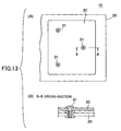
- An optical baseboard unit 10 is structured such that a board 30 serving as weight for removing vibration generated by a disk rotating at high speed is provided on an optical baseboard 20 that mounts a turntable motor (not shown), etc., as shown at (A) and (B) of Fig. 13, where the board 30 is fixed to the optical baseboard 20 by three screws 31, for example.
- the invention provides as follows.
- the present invention aims at providing a fixing structure of a board, and an optical disk apparatus that includes the fixing structure.
- the fixing structure of the present invention provides a slide mechanism for sliding a board on a baseboard, and a lock mechanism for locking the board to the baseboard.
- an eccentric rotor fabricated by an outsert process is provided on the baseboard, and an aperture is formed in the board; the eccentric rotor fits in through the aperture; when the eccentric rotor is rotated, the eccentric rotor pushes an edge of the aperture, and the board slides in relation to the baseboard.
- the slide mechanism is of a simple structure.
- the eccentric rotor has a plane section on the side that has the maximum eccentricity of an eccentric projecting portion; the aperture has a straight line-like edge; and when the eccentric rotor is rotated, the plane section of the eccentric projecting portion locks the straight line-like edge, which completes sliding of the board.
- This structure provides two advantageous features. Namely, a worker can determine when the rotational operation is complete by feel, and the eccentric rotor does not begin to turn due to vibration, etc.
- a portion that is diametrically opposite to the plane section is excised (removed).
- the size of the aperture, through which the eccentric projecting portion fits can be made smaller by the area equivalent to the portion that is excised, which provides a desirable result that the weight board is heavier.
- the lock mechanism for locking the board to the baseboard is constituted by a hook fabricated by an outsert process, having a hook section (projection), prepared on the baseboard, and an aperture, prepared in the board, in which the hook section fits; and when the board is slid, the edge of the aperture is locked by the hook section of the hook.
- the lock mechanism is of a simple structure.
- the present invention also provides an optical disk apparatus, wherein a baseboard includes a base unit that supports a motor for rotating a turntable that supports a disk, and an optical head for reading information stored by the disk; and the base unit is supported on a supporting base through an insulator, including a weight board that is fixed to the baseboard by the fixing structure of the present invention.
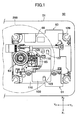
- Fig. 1 and Fig. 2 show an optical disk apparatus 50 according to an embodiment of the present invention.
- the section marked (A) shows an initial (idle) state
- the section marked (B) shows a state at the time of reading or writing (i.e., in operation).
- the disk tray is omitted.
- X1-X2 represents the width direction
- Y1-Y2 represents the depth direction
- Z1-Z2 represents the height direction.
- the optical disk apparatus 50 includes a housing 51 that is in the shape of a box, a disk tray (not shown), and a baseboard unit assembly 60, the optical disk apparatus 50 being horizontally installed in a computer, for example.
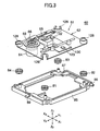
- the baseboard unit assembly 60 includes a baseboard unit 61 that is supported by a support baseboard 85 that is in the shape of a square frame, and mounted on flexible insulators 81 through 84 made of rubber for absorbing vibration, the insulators 81 through 84 being provided at the four corners of the baseboard unit assembly 60 and the support baseboard 85, as shown by Fig. 3.
- the baseboard unit 61 includes a baseboard 62 that is approximately in the shape of a square, which baseboard 62 further includes a turntable 63 for supporting a CD-ROM disk, a motor 64 for rotating the turntable 63, an optical head 65 for reading information on the CD-ROM disk, a motor 66 for moving the optical head 65, and a weight board 100.
- the weight board 100 is provided in order to improve reading characteristics of the optical disk apparatus 50, the weight board 100 providing a desired balance of the weight to be applied to the insulators 81 through 84 at the four corners, and setting the position of the center of gravity of the baseboard unit 61 at a desired position, while increasing the weight of the baseboard unit 61.
- the baseboard unit assembly 60 is supported in the housing 51 by axles 86 and 87 that are projected in the X1 and X2 directions, respectively, from the support baseboard 85 on the side of Y1, being supported by bearings 88 that are provided to the housing 51 on the side of Y1 (ref. Fig. 2), and a rod 89 provided on the side of Y2 of the support baseboard 85 being supported by a cam slot of a cam 90.
- the baseboard unit assembly 60 stays with its Y2 side lowered, and the turntable 63 is in a lower position as shown by the section marked (A) in Fig. 2.
- a CD-ROM disk 200 When a CD-ROM disk 200 is placed on a disk tray 20 (not illustrated), the disk tray 20 is moved in the Y1 direction, and the CD-ROM disk 200 is carried into the housing 51. Then, the cam 90 is moved in the Z1 direction, a slot provided to the cam (cam slot) pushes up the rod 89, and the baseboard unit assembly 60 is moved into a level state as shown by the section (B) of Fig. 2.
- the CD-ROM disk 200 is supported by the turntable 63, separated from the disk tray, and is clamped to the turntable 63 by a clamper 91. Then, the motor 64 rotates the CD-ROM disk 200 and the motor 66 moves the optical head 65 such that the optical head 65 reads the information stored in the CD-ROM disk 200.
- the optical disk apparatus 50 carries out operations in a sequence reverse to the above. That is, the baseboard unit assembly 60 inclines as shown by section (A) of Fig. 2, and the CD-ROM disk 200 is unclamped and discharged outside of the housing 51 by the disk tray (not shown).
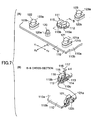
- Fig. 4 is a perspective drawing showing a correspondence between the weight board 100 and the baseboard 62.
- Fig. 5 shows how the weight board 100 is fixed to the baseboard 62.
- the section marked (A) shows the weight board 100 being placed on the baseboard 62, and the section marked (B) shows the cross-section thereof at B-B;
- the section marked (C) shows the weight board 100 being fixed to the baseboard 62 without using a screw, and the section marked (D) shows the cross-section thereof at D-D.
- Section (A) of Fig. 6 is a plan view of the baseboard 62
- section (B) of Fig. 6 is a bottom plan view of the baseboard 62
- Fig. 7 shows details of the portion relating to fixing of the weight board 100 to the baseboard 62.
- the baseboard 62 is fabricated by an outsert process carried out on a metal baseboard 110.
- items formed by the outsert fabrication include (refer to Fig. 6) an eccentric rotor 111, three hooks 121 through 123, and a pin 120 for fixing the weight board 100; a portion 125 for supporting the motor 64; a portion 126 in the shape of an aperture-and-closing lid for fixing the motor 66; a portion 127 for supporting a guide rod of the optical head 65; and portions 128 for fitting and inserting the insulators 81 through 84.
- the eccentric rotor 111 includes a flange section 112 on the upper surface 110a of the metal baseboard 110, a flange section 113 on the undersurface 110b of the metal baseboard 110, a connector section 114 in the shape of a pillar connecting the flange section 112 and the flange section 113 through a circular hole 110c in the metal baseboard 110, and an eccentric projecting portion 115 that projects above the flange section 112.
- the eccentric rotor 111 can be rotated with the connector section 114 serving as the center of rotation.
- a slot 116 is formed in the eccentric projecting portion 115 such that a tip of a screwdriver fits.
- a centerline 117 represents the centerline and the rotational axis of the connector section 114.
- a centerline 118 represents the centerline of the eccentric projecting portion 115. The centerline 118 is apart from the centerline 117 by ⁇ X, i.e., being made eccentric.
- the rotational position of the eccentric projecting portion 115 of the eccentric rotor 111 shown in sections (A) and (B) of Fig. 7 is in a state where the weight board 100 is fixed. Note that a plane section 115b of the eccentric projecting portion 115 faces the X2 direction. Conversely, the rotational position of the eccentric projecting portion 115 of the eccentric rotor section 111 shown in Fig. 8 is in a state where the weight board 100 is yet to be fixed. Note that the plane section 115b of the eccentric projecting portion 115 faces the X1 direction.
- the shape of the eccentric projecting portion 115 is explained with reference to Fig. 8.
- the shape of the eccentric projecting portion 115 basically is a pillar 119 having a radius R1 with its center at the centerline 118.
- the X1 side of the pillar 119 is flattened, forming the plane section 115b that is delimited by intersections 115d and 115e with circumference portions 115a.
- a wide plane section 115c is formed by removing a portion 119a that is delimited by a line in the Y1-Y2 directions, the shortest distance of the line from the centerline 118 being approximately equal to 1/2 of the radius R1.
- the radius R1 is greater than a distance A that is the distance between the centerline 118 and the central point of the plane section 115b (shortest distance).
- the circumference of the eccentric projecting portion 115 is constituted from the circumference portions 115a, the plane section 115b that is narrow, and the wide plane section 115c.
- the slot 116 is opened at the wide plane section 115c.
- the pin 120 (see Fig. 4 and Fig. 7) is of a pillar shape, and has a flange section 120a on the upper surface 110a of the metal baseboard 110.
- the hooks 121, 122, and 123 are distributed and arranged around the eccentric rotor 111.
- Each of the hooks 121, 122, and 123 is shaped like a pillar having a cross-section of approximately a half of an elongated circle (ellipse), wherein the X2 side is a circumference, and the X1 side is a plane; hook sections 121a, 122a, and 123a, respectively, are formed, which project from the X1 side of each hook to the X1 direction; and flange sections 121b, 122b, and 123b, respectively, are formed on the upper surface 110a of the metal baseboard 110.
- ellipse elongated circle
- the weight board 100 includes an aperture 101 corresponding to the eccentric projecting portion 115 of the eccentric rotor 111, an aperture 102 corresponding to the pin 120, and apertures 103, 104, and 105 corresponding to the hooks 121, 122, and 123, respectively.
- the aperture 101 is shaped like approximately a quarter of a circle, having an edge 101a that is in the shape of a straight line that extends in the Y1-Y2 directions on the X2 side. Since the portion equivalent to approximately 1/2 of the radius R1 is removed from the eccentric projecting portion 115 as mentioned above, the size of the aperture 101 is smaller than an aperture that would be required if the eccentric projecting portion 115 were a full pillar.
- the shape of the aperture 102 is of an ellipse, the major axis of which is in the X1-X2 directions.
- the apertures 103, 104, and 105 are each shaped in the form of about 1/2 of an ellipse, the major axis of which is in the X1-X2 directions, and have edges 103a, 104a, and 105a, respectively, each in the shape of a straight line that extends in the Y1-Y2 directions on the X1 side.
- Fixing of the weight board 100 to the baseboard 62 without using a screw is carried out through the following two stages.
- the rotational position of the plane section 115b of the eccentric projecting portion 115 of the eccentric rotor 111 is such that it faces the X1 side.
- the weight board 100 is placed on the baseboard 62 as shown by sections (A) and (B) of Fig. 5.
- the eccentric projecting portion 115 fits into the aperture 101
- the pin 120 fits into the aperture 102
- the hooks 121, 122, and 123 fit into the apertures 103, 104, and 105, respectively.
- the weight board 100 is placed on the baseboard 62 with positions determined.
- the portions around the apertures 101 through 105 are supported by flange sections 112, 120a and 121b through 123b, respectively.
- a screwdriver is used. Specifically, the tip of the screwdriver is applied to the slot 116, and is rotated clockwise as shown by C in Fig. 9 such that the eccentric rotor 111 is rotated 180 degrees.
- Sections (A), (B), (C) and (D) of Fig. 9 show how the eccentric rotor is rotated around the centerline 117 (rotational axis), and the eccentric projecting portion 115 is eccentrically rotated from the original position as shown by section (A) to the final position as shown by section (D) via states shown by sections (B) and (C).
- the eccentric projecting portion 115 rotates inside the aperture 101.
- the circumference portion 115a pushes the edge 101a, of the aperture 101, the edge 101a having the shape of a straight line.
- the weight board 100 is horizontally pushed, i.e., in the X2 direction.
- the intersection 115e pushes the edge 101a as shown by section (C) of Fig. 9.
- the plane section 115b pushes the edge 101a.
- the weight board 100 is pushed in the X2 direction, while the apertures 102 through 105 guide the pin 120 and the hooks 121, 122, and 123, respectively.
- the edges 103a, 104a, and 105a (that are straight line-like) of the apertures 103, 104, and 105, respectively, come under the hook sections 121a, 122a, and 123a, respectively, and are locked, pushing the hooks 121, 122, and 123, respectively.
- the eccentric rotor 111 pushes the edge of the aperture 101 in the X2 direction, and the hooks 121, 122, and 123 push the edges of the apertures 103, 104, and 105, respectively, in the X1 direction.
- the weight board 100 is fixed to the baseboard 62, leaving no freedom to move in any of the X, Y, and Z directions, by turning the eccentric rotor 111, and using no screws.
- motion in the X1-X2 directions is restrained by the eccentric rotor 111 and the hooks 121, 122, and 123.
- Motion in the Y1-Y2 directions is restrained by the pin 120 and the hook sections 121a, 122a, and 123a.
- Motion in the Z1 direction is restrained by the hook sections 121a, 122a and 123a.
- a taper may be provided to each of the hooks 121, 122, and 123, as illustrated only for the hook 122 in Fig. 7, or, alternatively, a taper may be provided to the flange section 112 of the rotor 11 such that the movement in the Z direction is further restricted.
- the present invention realizes fixing of the weight board 100 to the baseboard 62 with fewer components, and less work.
- the three hooks namely, the hooks 121, 122, and 123 are provided at three points distributed over the weight board 100. Accordingly, the motion is restrained at the three points; and the weight board 100, even if its size is large, is firmly fixed. Further, one operation is sufficient for firmly fixing the weight board 100 to the baseboard 62.
- the weight board 100 becomes free to move in the X directions, and possibly becomes separated from the baseboard 62.
- the intersections 115d and 115e need to push the edge 101a for the eccentric rotor 111 to start rotating from the state shown by section (D) of Fig. 5 such that the weight board 100 is displaced a little in the X2 direction. For this reason, even if vibration or shock is applied, the eccentric rotor 111 does not start rotating from the state shown by section (D) of Fig. 5, and accordingly, the weight board 100 is firmly fixed.
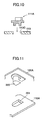
- Fig. 10 shows the first variation, wherein an eccentric rotor 111A is not formed by outsert fabrication, but is an independent component, and the eccentric rotor 111A is to be inserted in and attached to a circular hole 110c provided in the metal baseboard 110.
- Fig. 11 shows the second variation, wherein a hook 300 is provided to the weight board 100A, and an aperture 301 is provided in the metal baseboard 110A, instead of providing the hooks 121, 122, and 123 to the metal baseboard 110 as described above.
- Fig. 12 shows the third variation, wherein a hook 400, corresponding to the above-mentioned hooks 121, 122, and 123, is formed by a press process carried out on a part of a metal baseboard 110B.
- a press process may be employed to make the hook 400 on the weight board 110B.
- the present invention is applicable not only to fixing a weight board to a baseboard of an optical disk apparatus, but to fixing any board-shaped component to another board.
- the structure for fixing a first board (such as the weight board) to a second board (such as the baseboard) carries out fixing by sliding one of the first board and the second board in relation to the other board by a slide mechanism (such as the eccentric rotor pushing the edge of the aperture), and by locking by a lock mechanism (such as the hook and the aperture edge).
- a slide mechanism such as the eccentric rotor pushing the edge of the aperture
- a lock mechanism such as the hook and the aperture edge
Landscapes
- Engineering & Computer Science (AREA)
- General Engineering & Computer Science (AREA)
- Mechanical Engineering (AREA)
- Connection Of Plates (AREA)
Applications Claiming Priority (2)
| Application Number | Priority Date | Filing Date | Title |
|---|---|---|---|
| JP2002372424A JP2004204889A (ja) | 2002-12-24 | 2002-12-24 | 板状部材の固定構造及びこの構造を有するディスク装置 |
| JP2002372424 | 2002-12-24 |
Publications (2)
| Publication Number | Publication Date |
|---|---|
| EP1434208A2 true EP1434208A2 (de) | 2004-06-30 |
| EP1434208A3 EP1434208A3 (de) | 2007-04-11 |
Family
ID=32463514
Family Applications (1)
| Application Number | Title | Priority Date | Filing Date |
|---|---|---|---|
| EP03257985A Withdrawn EP1434208A3 (de) | 2002-12-24 | 2003-12-18 | Montageplattenbefestigungsstruktur und damit versehenes Plattengerät |
Country Status (3)
| Country | Link |
|---|---|
| US (1) | US20040128678A1 (de) |
| EP (1) | EP1434208A3 (de) |
| JP (1) | JP2004204889A (de) |
Cited By (2)
| Publication number | Priority date | Publication date | Assignee | Title |
|---|---|---|---|---|
| DE102010022215A1 (de) * | 2010-05-20 | 2011-11-24 | Rational Ag | Motorbefestigung insbesondere für ein Gargerät |
| CN107429814A (zh) * | 2015-03-20 | 2017-12-01 | 小仓离合器有限公司 | 动力传输装置 |
Families Citing this family (7)
| Publication number | Priority date | Publication date | Assignee | Title |
|---|---|---|---|---|
| JP3810715B2 (ja) * | 2002-07-30 | 2006-08-16 | 松下電器産業株式会社 | ディスクチェンジャ装置 |
| WO2007026398A1 (ja) * | 2005-08-30 | 2007-03-08 | Fujitsu Limited | 磁気ディスク装置 |
| KR101312439B1 (ko) * | 2007-03-12 | 2013-09-27 | 삼성전자주식회사 | 광 디스크 드라이브 |
| CN101662912B (zh) * | 2008-08-29 | 2012-01-11 | 英业达股份有限公司 | 电路板旋转定位结构 |
| US8854935B2 (en) * | 2011-08-22 | 2014-10-07 | Mitsubishi Electric Corporation | Disk drive device |
| JP5996931B2 (ja) * | 2012-05-16 | 2016-09-21 | 株式会社くろがね工作所 | ラッチ操作レバー支持装置 |
| WO2015129518A1 (ja) * | 2014-02-25 | 2015-09-03 | 小倉クラッチ株式会社 | 動力伝達装置 |
Family Cites Families (12)
| Publication number | Priority date | Publication date | Assignee | Title |
|---|---|---|---|---|
| GB843929A (en) * | 1957-09-04 | 1960-08-10 | Ericsson Telephones Ltd | An improved system of and means for locating and detachably locking components to a support |
| DE2328412C3 (de) * | 1973-06-04 | 1975-11-27 | Springfix-Befestigungstechnik Gmbh, 7335 Salach | Befestigungselement |
| US4941841A (en) * | 1988-06-09 | 1990-07-17 | Darden Julius C | Adapter and a removable slide-in cartridge for an information storage system |
| US5222897A (en) * | 1992-04-01 | 1993-06-29 | Emc Corporation | Circuit board inserter/ejector system |
| JP2877135B2 (ja) * | 1997-04-18 | 1999-03-31 | 日本電気株式会社 | 多段連結電子部品モジュール |
| AUPO663397A0 (en) * | 1997-05-06 | 1997-05-29 | Hedweld Engineering Pty Ltd | Rotating locking arrangement |
| US6067225A (en) * | 1997-08-04 | 2000-05-23 | Sun Microsystems, Inc. | Disk drive bracket |
| EP0971572A1 (de) * | 1998-07-10 | 2000-01-12 | Edward A. Reddicliffe | Befestigungmechanismus für eine Zweikomponentige Vorrichtung |
| JP2000091756A (ja) * | 1998-09-14 | 2000-03-31 | Fujitsu Ltd | 電子機器、部品ユニット及びアタッチメント |
| US6217359B1 (en) * | 2000-02-01 | 2001-04-17 | Dean Chang | Mobile rack for removable hard disk driver |
| JP2003297484A (ja) * | 2001-11-19 | 2003-10-17 | Yamaichi Electronics Co Ltd | カードコネクタ |
| US6785141B2 (en) * | 2002-10-03 | 2004-08-31 | Quanta Computer, Inc. | Locking and ejecting device for removable module in a portable computer |
-
2002
- 2002-12-24 JP JP2002372424A patent/JP2004204889A/ja not_active Withdrawn
-
2003
- 2003-12-16 US US10/736,813 patent/US20040128678A1/en not_active Abandoned
- 2003-12-18 EP EP03257985A patent/EP1434208A3/de not_active Withdrawn
Cited By (3)
| Publication number | Priority date | Publication date | Assignee | Title |
|---|---|---|---|---|
| DE102010022215A1 (de) * | 2010-05-20 | 2011-11-24 | Rational Ag | Motorbefestigung insbesondere für ein Gargerät |
| DE102010022215B4 (de) | 2010-05-20 | 2023-05-25 | Rational Ag | Motorbefestigung insbesondere für ein Gargerät |
| CN107429814A (zh) * | 2015-03-20 | 2017-12-01 | 小仓离合器有限公司 | 动力传输装置 |
Also Published As
| Publication number | Publication date |
|---|---|
| US20040128678A1 (en) | 2004-07-01 |
| JP2004204889A (ja) | 2004-07-22 |
| EP1434208A3 (de) | 2007-04-11 |
Similar Documents
| Publication | Publication Date | Title |
|---|---|---|
| EP1434208A2 (de) | Montageplattenbefestigungsstruktur und damit versehenes Plattengerät | |
| US6195839B1 (en) | Hinged detent | |
| JP5291778B2 (ja) | ヒンジ装置 | |
| JP2002039161A (ja) | ヒンジユニット及びヒンジ構造 | |
| AU2003202451B2 (en) | Musical stand | |
| JP2000067700A (ja) | 押圧・回動操作型電子部品およびこれを用いた通信端末機器 | |
| JP2012145730A (ja) | 譜面台装置 | |
| US7252350B2 (en) | Pedestal assembly for computer enclosures | |
| US6637898B2 (en) | Manually foldable door mirror | |
| EP1528585A2 (de) | Kombinierter Betätigungsmechanismus | |
| US4890533A (en) | Key device for electronic keyboard musical instrument | |
| EP0990818B1 (de) | Tragvorrichtung für einen beweglichen Körper | |
| JPH08210838A (ja) | 測量機の目盛盤回転装置 | |
| JPH0755379Y2 (ja) | 角度調整機構 | |
| JP2669774B2 (ja) | ヒンジ装置 | |
| JPH088554A (ja) | 被取付け体の支持機構 | |
| US20060123439A1 (en) | Pick-up angle adjustment mechanism for optical disk apparatus | |
| JP2003199636A (ja) | 引出し装置 | |
| JPH09204267A (ja) | 入力装置 | |
| JPH09170372A (ja) | ヒンジ装置 | |
| JPH062094Y2 (ja) | 測量機本体と整準台との連結機構 | |
| CN2366941Y (zh) | 光碟机的光学头承载基板 | |
| JPH0435927Y2 (de) | ||
| JPH0630096A (ja) | チルトフット機構 | |
| JPH08293065A (ja) | キャッシュレジスタ |
Legal Events
| Date | Code | Title | Description |
|---|---|---|---|
| PUAI | Public reference made under article 153(3) epc to a published international application that has entered the european phase |
Free format text: ORIGINAL CODE: 0009012 |
|
| AK | Designated contracting states |
Kind code of ref document: A2 Designated state(s): AT BE BG CH CY CZ DE DK EE ES FI FR GB GR HU IE IT LI LU MC NL PT RO SE SI SK TR |
|
| AX | Request for extension of the european patent |
Extension state: AL LT LV MK |
|
| PUAL | Search report despatched |
Free format text: ORIGINAL CODE: 0009013 |
|
| AK | Designated contracting states |
Kind code of ref document: A3 Designated state(s): AT BE BG CH CY CZ DE DK EE ES FI FR GB GR HU IE IT LI LU MC NL PT RO SE SI SK TR |
|
| AX | Request for extension of the european patent |
Extension state: AL LT LV MK |
|
| STAA | Information on the status of an ep patent application or granted ep patent |
Free format text: STATUS: THE APPLICATION IS DEEMED TO BE WITHDRAWN |
|
| AKX | Designation fees paid | ||
| 18D | Application deemed to be withdrawn |
Effective date: 20070703 |
|
| REG | Reference to a national code |
Ref country code: DE Ref legal event code: 8566 |