EP1434221A2 - Magnetplattenlaufwerk - Google Patents
Magnetplattenlaufwerk Download PDFInfo
- Publication number
- EP1434221A2 EP1434221A2 EP04001599A EP04001599A EP1434221A2 EP 1434221 A2 EP1434221 A2 EP 1434221A2 EP 04001599 A EP04001599 A EP 04001599A EP 04001599 A EP04001599 A EP 04001599A EP 1434221 A2 EP1434221 A2 EP 1434221A2
- Authority
- EP
- European Patent Office
- Prior art keywords
- magnetic disc
- shroud
- disc
- gap
- flutter
- Prior art date
- Legal status (The legal status is an assumption and is not a legal conclusion. Google has not performed a legal analysis and makes no representation as to the accuracy of the status listed.)
- Withdrawn
Links
Images


Classifications
-
- G—PHYSICS
- G11—INFORMATION STORAGE
- G11B—INFORMATION STORAGE BASED ON RELATIVE MOVEMENT BETWEEN RECORD CARRIER AND TRANSDUCER
- G11B33/00—Constructional parts, details or accessories not provided for in the other groups of this subclass
- G11B33/14—Reducing influence of physical parameters, e.g. temperature change, moisture, dust
- G11B33/148—Reducing friction, adhesion, drag
-
- G—PHYSICS
- G11—INFORMATION STORAGE
- G11B—INFORMATION STORAGE BASED ON RELATIVE MOVEMENT BETWEEN RECORD CARRIER AND TRANSDUCER
- G11B25/00—Apparatus characterised by the shape of record carrier employed but not specific to the method of recording or reproducing, e.g. dictating apparatus; Combinations of such apparatus
- G11B25/04—Apparatus characterised by the shape of record carrier employed but not specific to the method of recording or reproducing, e.g. dictating apparatus; Combinations of such apparatus using flat record carriers, e.g. disc, card
- G11B25/043—Apparatus characterised by the shape of record carrier employed but not specific to the method of recording or reproducing, e.g. dictating apparatus; Combinations of such apparatus using flat record carriers, e.g. disc, card using rotating discs
-
- G—PHYSICS
- G11—INFORMATION STORAGE
- G11B—INFORMATION STORAGE BASED ON RELATIVE MOVEMENT BETWEEN RECORD CARRIER AND TRANSDUCER
- G11B33/00—Constructional parts, details or accessories not provided for in the other groups of this subclass
- G11B33/02—Cabinets; Cases; Stands; Disposition of apparatus therein or thereon
- G11B33/08—Insulation or absorption of undesired vibrations or sounds
Definitions
- the present invention relates to a rotary recording apparatus for reading and writing data from and to a rotating disc by means of a magnetic head, an optical head or the like, and in particular to a magnetic disc unit which can reduce fluid oscillation induced on a rotating disc so as to carry out positioning with a high degree of accuracy.
- a shroud is provided around the outer periphery of a disc with a predetermined gap between the disc and the shroud in order to reduce bounce (which well be hereinbelow referred to as "flutter") of the disc.
- bounce which well be hereinbelow referred to as "flutter"
- the distance between the inner wall of the shroud and the outer periphery of the disc is changed from 12 mm to 10 mm, and as a result, the amplitude of oscillation is decreased from about 20f ⁇ to 10f ⁇ .
- the amplitude of oscillation is decreased to 15f ⁇ , and if the distance is set to be less than 3 mm, the amplitude of oscillation becomes 8f ⁇ which is relatively small. That is, if the outer periphery of the magnetic disc and the inner wall of the shroud is set to a value below 3 mm, the oscillation can be minimized.
- a fluid force serving as an excitation source is reduced.
- the pressure distribution is made to be uniform over the surface of a disc.
- the stiffness of a disc is increased in order to decrease oscillation of a disc.
- the thickness of a disc may be increased to increase the stiffness of the disc, an increase in the thickness thereof causes a disc unit to have a larger size, and accordingly, it is unpreferable.
- An object of the present invention is to provide a rotary recording apparatus which can, on one hand, prevent flutter causing errors in positioning from increasing even though the rotational speed becomes higher, and which can, on the other hand, enhance the degree of positional accuracy for coping with a large storage capacity.
- a large capacity magnetic disc unit which can reduce a fluid force serving as an excitation source so as to prevent occurrence of flutter in order to restrain occurrence of noise or the like, and which can read and write data from and onto a disc with a high degree of accuracy.
- a shroud (outer wall) is provided around the entire periphery of a'rotating disc, except an insertion part thereof for a carriage arm, and a gap between the shroud and the outer periphery of the disc is set to be not less than 0.1 mm but not greater than 0.6 mm.
- An air stream induced during rotation of a disc causes a pressure differential between the upper and lower surfaces of the disc, which causes excitation of the disc, resulting in flutter of the disc. If the gap between the shroud and the disc is set to be narrower than a predetermined value, air on the upper and lower surfaces of the disc is isolated so as to reduce the pressure differential.
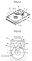
- a magnetic head 3 for recording and reproducing data is carried on a slider 4 which is supported by a magnetic head support mechanism 5 connected to a guide arm 6.
- a carriage 9 is composed of the guide arm 6, a pivot bearing 7 and a voice coil motor (which will be hereinbelow referred to as "VMC") 8, and the guide arm 6 is rotated by the VMC 8 around the pivot bearing 7. Further, these elements are set on a casting base 10 which is surrounded by a wall (shroud 20).
- a gap between the outer peripheries of the discs 1 and the inner wall of the shroud 20 is maintained at a predetermined distance (which will be referred to as "disc-shroud gap").
- the shroud 20 and the base 10 are made of the same casting material, being integrally incorporated with each other.
- the shroud 20 is formed therein with an opening 30 for introducing the guide arm 6 therethough onto a surface of a disc 1.
- the opening angle of the opening 30 is selected so as to be minimized while to allow the arm to be simply assembled and to prevent the arm from making contact with the shroud even through the head is shifted from the inner periphery to the outer periphery of the disc.
- the opening angle is set to about 45 deg.
- a wall is formed along the entire periphery of the base 10 of the unit. Further, this wall serves as a part of the shroud 20 surrounding the outer peripheries of the discs 1. However, the shroud 20 is arranged to branch off from the wall in the vicinity of the opening 30 so as to surround the discs 1.
- the wall serves as a surrounding wall 40 for surrounding the carriage 9 so as to hermetically enclose the unit.
- the wall surrounding the discs 1 will be hereinbelow defined and referred to as the shroud 20.
- the gap between the shroud 20 and the end faces of the discs 1 is regulated within a predetermined range so as to reduce the amplitude of flutter which would occur during rotation of the disc at a high speed, in order to restrain occurrence of noise. Detailed explanation will be hereinbelow made of this measure.
- Fig. 2 which is a sectional view along line A-A in Fig. 1B, the definition to the disc-shroud gap will be clarified.
- the spindle motor 2 is mounted on the base 10, having a shaft on which the discs 1 are stacked.
- the base 10 is incorporated with the shroud 20, being integrally molded therewith.
- the inner wall 21 of the shroud 20 is arranged along the entire periphery of the discs with a predetermined gap being held from the edge faces 11 of the discs 1 (this gap will be hereinbelow referred to as "disc-shroud gap"), except that the opening (which is not shown in Fig. 2) for introducing the arm 6 is formed in a part where the arm 6 of the carriage 9 is introduced onto a surface of a disc 1.
- the inner wall of the shroud is substantially circular, having a center which is substantially aligned with the rotating center of the discs 1 or the spindle motor 2. Accordingly, the above-mentioned disc-shroud gap is substantially uniform around the entire peripheries of the discs 1, except that the opening, that is, the insertion part for the arm 6, where no shroud 20 is formed.
- Fig. 3 there are shown results of measurements for relationship between the disc-shroud gap and the amplitude of flutter. Specifically, with the use of magnetic discs having an outer diameter of 3.5 inches, the discs were rotated at 7,200 rpm while amplitudes of flutter were measured by a displacement gage utilizing LDV (laser Doppler Velocity) while the disc-shroud gap is changed from 0.2 mm, to 0.4 mm, 0.6 mm, 0.81.2 mm, 2.5 mm, 4mm and to 6 mm. The results of the measurements, which are averaged and normalized, that is, are non-dimensional values, are shown in Fig. 3.
- LDV laser Doppler Velocity
- the amplitude of flutter is decreased as the disc-shroud gap is decreased to a value less than 0.6 mm. Further, the amplitude of flutter is not appreciably decreased in a range from 0.6 mm to 6 mm. Meanwhile, in the case of less than 0.6 mm, if the disc-shroud gap is decreased to 0.4 mm and to 0.2 mm, the amplitude of flutter can be reduced, remarkably. Specifically, if the shroud gap is 0.2 mm, the amplitude of flutter can be decreased to a value which is about 1/10 of the amplitude of flutter obtained with a disc-shroud gap of 0.6 mm.
- the disc-shroud gap is set to 0.4 mm. With this arrangement, the amplitude of flutter can be reduced to about a half of that obtained at a disc-shroud gap of about 1 mm. Of course, a disc-shroud gap of about 0.5 mm is also effective. It is desirable that the disc-shroud gap is narrower since the amplitude of flutter can become smaller. However, in view of the assembly of a disc unit, the narrower the disc-shroud gap, the more the difficulty in assembling the magnetic disc unit.
- the disc-shroud gap it would be practically impossible to set the disc-shroud gap to a value less than 0.1 mm, in view of a diametrical tolerance ( ⁇ 0.05 mm) of discs which are available at present and the erection tolerance between discs and spindles.
- a diametrical tolerance ⁇ 0.05 mm
- the flutter can be reduced by setting the disc-shroud gap in a range which is not less than 0.1 mm but not greater than 0.6 mm.
- Figs. 4A to 4D show contour lines of air pressure differentials between the outer and rear surfaces of a rotating disc, which were obtained from results of flow analysis in such a condition that the disc-shroud gap is narrowed.
- Figs. 4A to 4D show those with a disc-shroud gap of 2 mm, 1 mm, 0.5 mm and 0.2 mm, respectively.
- contour lines have crest peaks on the outer peripheral side of the disc in the case of a disc-shroud gap of 2 mm or 1 mm. These pressure differentials becomes excitation forces applied to the disc, causing the disc to flutter. Meanwhile, in the case of a small disc-shroud gap of 0.5 mm or 0.2 mm, no contour lines having crest peaks of pressure differentials causing occurrence of flutter, are found. In other words, no pressure differentials are produced, and accordingly, the amplitude of flutter becomes smaller.
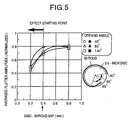
- a high speed magnetic disc unit in which the outer diameter of discs is 2.5 inches, and the rotational speed is 12,600 rpm, and the opening 30 has an opening angle of 140 deg. was prepared, and tested for flutter in the following measuring conditions: Rotational speed 12,600 rpm Disc thickness 0.8 mm Measuring position topmost and outermost of disc Measuring Method flutter amplitudes were measured at five low frequencied by LVD Averaged values each obtained from the five measured amplitudes were comparatively considered (Refer to Fig. 5)
- the results of these measurements show that a smaller disc-shroud gap is effective for reducing flutter, similar to the effects mentioned before.
- the disc-shroud gap is set to 0.4 mm. Accordingly, the amplitude of flutter can be reduced by about 10%. Further, if the disc-shroud gap is set to 0.2 mm, the flutter can be reduced by about 50%.
- the opening angle of the opening 30 is set to 45 deg., 65 deg. and to 140 deg. respectively, no distinctive difference was appreciated in the effects of reducing the amplitude of flutter by decreasing the disc-shroud gap. Namely, it has been experimentally confirmed that the flutter can be reduced by decreasing the disc-flutter gap if the opening angle was changed from 45 deg. to 140 deg. Thus, the opening angle of the opening 30 is set to about 140 deg. in view of simplicity of the assembly of the apparatus.
- the lower limit values of the disc-shroud gap must be set to a value greater than 0.1 mm in view of the manufacturing tolerance of outer diameter dimensions of discs and the erection tolerance of the disc unit.
- the shroud 20 is made of the same casting material as that of the base 10, and is integrally incorporated with the base 10, the shroud 20 may be formed, independent from the base 10, in order to enhance the processing accuracy and the processing performance thereof, and thereafter, it may be assembled to the base 10. Alternatively, the shroud may be machined. Further, even through the disc-shroud gap is different between the uppermost and lowermost ones of the stacked discs due to a die drawing gradient of the base mold dies, it had been confirmed that the same technical effects and advantages as that of the first embodiment may be obtained if the minimum disc-shroud gap is set to a value less than 0.6 mm or 0.4 mm.
- a cylindrical shroud is provided around magnetic discs stacked on the shaft of a spindle motor, and a gap between the shroud and the outer end faces of the discs is set in a predetermined range (not less than 0.1 but not greater than 0.6 mm), a high speed and large storage capacity magnetic disc unit can be provided.
Landscapes
- Supporting Of Heads In Record-Carrier Devices (AREA)
- Holding Or Fastening Of Disk On Rotational Shaft (AREA)
- Moving Of Heads (AREA)
Applications Claiming Priority (3)
| Application Number | Priority Date | Filing Date | Title |
|---|---|---|---|
| JP03085398A JP3732001B2 (ja) | 1998-02-13 | 1998-02-13 | 磁気ディスク装置 |
| JP3085398 | 1998-02-13 | ||
| EP99101775A EP0936614B1 (de) | 1998-02-13 | 1999-02-12 | Magnetische Platteneinheit |
Related Parent Applications (1)
| Application Number | Title | Priority Date | Filing Date |
|---|---|---|---|
| EP99101775A Division EP0936614B1 (de) | 1998-02-13 | 1999-02-12 | Magnetische Platteneinheit |
Publications (2)
| Publication Number | Publication Date |
|---|---|
| EP1434221A2 true EP1434221A2 (de) | 2004-06-30 |
| EP1434221A3 EP1434221A3 (de) | 2004-12-01 |
Family
ID=12315282
Family Applications (2)
| Application Number | Title | Priority Date | Filing Date |
|---|---|---|---|
| EP04001599A Withdrawn EP1434221A3 (de) | 1998-02-13 | 1999-02-12 | Magnetplattenlaufwerk |
| EP99101775A Expired - Lifetime EP0936614B1 (de) | 1998-02-13 | 1999-02-12 | Magnetische Platteneinheit |
Family Applications After (1)
| Application Number | Title | Priority Date | Filing Date |
|---|---|---|---|
| EP99101775A Expired - Lifetime EP0936614B1 (de) | 1998-02-13 | 1999-02-12 | Magnetische Platteneinheit |
Country Status (4)
| Country | Link |
|---|---|
| US (4) | US6751050B1 (de) |
| EP (2) | EP1434221A3 (de) |
| JP (1) | JP3732001B2 (de) |
| DE (1) | DE69943403D1 (de) |
Families Citing this family (12)
| Publication number | Priority date | Publication date | Assignee | Title |
|---|---|---|---|---|
| US6665139B2 (en) * | 1998-02-13 | 2003-12-16 | Hitachi, Ltd. | Magnetic-disc unit with gap between disc and shroud |
| JP3732001B2 (ja) * | 1998-02-13 | 2006-01-05 | 株式会社日立グローバルストレージテクノロジーズ | 磁気ディスク装置 |
| JP3728169B2 (ja) | 2000-03-17 | 2005-12-21 | 富士通株式会社 | ディスク装置 |
| JP2002133827A (ja) * | 2000-10-27 | 2002-05-10 | Internatl Business Mach Corp <Ibm> | ディスク・ドライブ装置、ハード・ディスク・ドライブおよびハード・ディスク・ドライブの筐体 |
| US6961207B2 (en) * | 2001-05-10 | 2005-11-01 | Samsung Electronics Co., Ltd. | Apparatus and method for dampening disk vibration in storage devices |
| JP4201685B2 (ja) | 2003-10-31 | 2008-12-24 | パイオニア株式会社 | ディスク装置 |
| JP2006079745A (ja) * | 2004-09-10 | 2006-03-23 | Hitachi Global Storage Technologies Netherlands Bv | 磁気ディスク装置 |
| JP2007250027A (ja) | 2006-03-14 | 2007-09-27 | Hitachi Global Storage Technologies Netherlands Bv | 回転円板の制振機構および情報記録装置並びに磁気ディスク装置 |
| JP2009245570A (ja) * | 2008-03-31 | 2009-10-22 | Hitachi Global Storage Technologies Netherlands Bv | ベースの製造方法及びディスク・ドライブ装置の製造方法 |
| KR20110091376A (ko) | 2010-02-05 | 2011-08-11 | 삼성전자주식회사 | 2단의 오목부를 가진 베이스 부재와 이를 하드 디스크 드라이브 |
| US8922942B2 (en) | 2011-06-09 | 2014-12-30 | Hitachi, Ltd. | Magnetic disk apparatus |
| US8896964B1 (en) | 2013-05-16 | 2014-11-25 | Seagate Technology Llc | Enlarged substrate for magnetic recording medium |
Family Cites Families (33)
| Publication number | Priority date | Publication date | Assignee | Title |
|---|---|---|---|---|
| BE794003A (fr) * | 1972-01-13 | 1973-05-02 | Memorex Corp | Systeme pour regir une circulation d'air |
| JPS54154310A (en) * | 1978-05-25 | 1979-12-05 | Fujitsu Ltd | Magnetic disc apparatus |
| US4280155A (en) * | 1979-06-04 | 1981-07-21 | Memorex Mini Disc Drive Corp. | Method of improving air flow in compact disc drive |
| JPS5972680A (ja) * | 1982-10-20 | 1984-04-24 | Hitachi Ltd | 磁気ディスク装置 |
| JPS5984386A (ja) * | 1982-11-08 | 1984-05-16 | Hitachi Ltd | 磁気ディスク装置 |
| US4583213A (en) | 1984-07-06 | 1986-04-15 | Storage Technology Partners Ii | Air shroud for data storage disks |
| US4660010A (en) * | 1985-10-15 | 1987-04-21 | Ledex, Inc. | Rotary latching solenoid |
| JP2856459B2 (ja) | 1989-11-08 | 1999-02-10 | 株式会社東芝 | ディスク装置 |
| JPH05234327A (ja) * | 1992-02-19 | 1993-09-10 | Hitachi Ltd | 小型磁気ディスク装置 |
| JP3057345B2 (ja) * | 1992-09-25 | 2000-06-26 | 株式会社日立製作所 | 回転円板型記憶装置 |
| EP0657889A1 (de) * | 1993-12-09 | 1995-06-14 | Teac Corporation | Festplattenantrieb mit verringerter Lustungsaufnahme |
| JPH07320478A (ja) | 1994-05-27 | 1995-12-08 | Hitachi Ltd | 回転円板型記憶装置 |
| US5631787A (en) * | 1994-06-27 | 1997-05-20 | Quantum Corporation | Power reduction shroud for a hard disk drive |
| US6239943B1 (en) * | 1994-07-22 | 2001-05-29 | Seagate Technology Llc | Squeeze film damping for a hard disc drive |
| JP2867911B2 (ja) * | 1994-08-16 | 1999-03-10 | 日本電気株式会社 | 磁気ディスク装置 |
| CN1182526C (zh) * | 1994-10-17 | 2004-12-29 | 日立环球储存科技荷兰有限公司 | 具有磁盘运动限制器的直接存取存储器 |
| US5541791A (en) * | 1994-11-17 | 1996-07-30 | Quantum Corporation | Air guide for an aerodynamic actuator latch within a disk drive |
| US5696649A (en) * | 1995-05-22 | 1997-12-09 | International Business Machines Corporation | Elastic insert shroud to provide maximum effective shrouding shock mitigation and filtering in high speed disk drives |
| US5801899A (en) * | 1995-10-06 | 1998-09-01 | Seagate Technology, Inc. | Mechanical shock protection for a disc drive |
| JP2760374B2 (ja) | 1996-01-26 | 1998-05-28 | 日本電気株式会社 | 磁気ディスク装置 |
| US5898545A (en) * | 1997-07-01 | 1999-04-27 | International Business Machines Corporation | Head load/unload and disk airflow control apparatus |
| US5907453A (en) * | 1997-07-08 | 1999-05-25 | Seagate Technology, Inc. | Enhanced convective voice coil cooling to improve the operational performance of a disc drive |
| US5956203A (en) * | 1997-08-26 | 1999-09-21 | International Business Machines Corporation | Disk drive having an insert with a channel for directing air flow to a rotary actuator voicecoil |
| US6271987B1 (en) * | 1997-08-28 | 2001-08-07 | Seagate Technology Llc | Circumferentially extending disc snubber |
| JP3149394B2 (ja) | 1997-10-29 | 2001-03-26 | インターナショナル・ビジネス・マシーンズ・コーポレ−ション | 包囲部材、ディスク装置及びその製造方法 |
| US6369978B1 (en) * | 1998-07-17 | 2002-04-09 | Hitachi, Ltd. | Magnetic disk apparatus with shroud having opening downstream of moveable arm |
| US6665139B2 (en) * | 1998-02-13 | 2003-12-16 | Hitachi, Ltd. | Magnetic-disc unit with gap between disc and shroud |
| JP3732001B2 (ja) * | 1998-02-13 | 2006-01-05 | 株式会社日立グローバルストレージテクノロジーズ | 磁気ディスク装置 |
| US6600626B2 (en) * | 1998-07-17 | 2003-07-29 | Hitachi, Ltd. | Magnetic disk apparatus |
| US6462901B1 (en) * | 1999-02-22 | 2002-10-08 | Seagate Technology Llc | Ribbed shrouding spacer and method for reducing flutter and windage losses in disc drives |
| JP2000331460A (ja) * | 1999-05-21 | 2000-11-30 | Naruse Atsushi | ディスクフラッタ制振装置 |
| JP3987235B2 (ja) * | 1999-06-08 | 2007-10-03 | 富士通株式会社 | 記録ディスク駆動装置およびその製造方法 |
| US6961207B2 (en) * | 2001-05-10 | 2005-11-01 | Samsung Electronics Co., Ltd. | Apparatus and method for dampening disk vibration in storage devices |
-
1998
- 1998-02-13 JP JP03085398A patent/JP3732001B2/ja not_active Expired - Fee Related
-
1999
- 1999-02-10 US US09/247,550 patent/US6751050B1/en not_active Expired - Fee Related
- 1999-02-12 EP EP04001599A patent/EP1434221A3/de not_active Withdrawn
- 1999-02-12 EP EP99101775A patent/EP0936614B1/de not_active Expired - Lifetime
- 1999-02-12 DE DE69943403T patent/DE69943403D1/de not_active Expired - Lifetime
-
2003
- 2003-10-08 US US10/680,235 patent/US7072141B2/en not_active Expired - Fee Related
-
2006
- 2006-03-24 US US11/387,903 patent/US7336440B2/en not_active Expired - Fee Related
-
2007
- 2007-12-21 US US11/962,340 patent/US7643245B2/en not_active Expired - Fee Related
Also Published As
| Publication number | Publication date |
|---|---|
| US7336440B2 (en) | 2008-02-26 |
| EP0936614B1 (de) | 2011-05-04 |
| US20040070866A1 (en) | 2004-04-15 |
| US20060164754A1 (en) | 2006-07-27 |
| JPH11232866A (ja) | 1999-08-27 |
| DE69943403D1 (de) | 2011-06-16 |
| JP3732001B2 (ja) | 2006-01-05 |
| EP0936614A1 (de) | 1999-08-18 |
| US7643245B2 (en) | 2010-01-05 |
| US7072141B2 (en) | 2006-07-04 |
| US6751050B1 (en) | 2004-06-15 |
| US20080106819A1 (en) | 2008-05-08 |
| EP1434221A3 (de) | 2004-12-01 |
Similar Documents
| Publication | Publication Date | Title |
|---|---|---|
| US7643245B2 (en) | Magnetic disc unit with gap between magnetic disc and shroud | |
| US6665139B2 (en) | Magnetic-disc unit with gap between disc and shroud | |
| US5396386A (en) | Roll insensitive air bearing slider | |
| US5737151A (en) | Roll insensitive air bearing slider | |
| AU603703B2 (en) | Flexible disk cassette | |
| US20020171972A1 (en) | Recording disk drive and method of assembling the same | |
| EP1213708A2 (de) | Platteneinheit mit verbessertem Kopfpositionierungs-Genauigkeit | |
| US7420775B2 (en) | Hard disk drive | |
| US4819100A (en) | Floating head slider device for magnetic disk apparatus | |
| US6081990A (en) | Method for incorporating disk media into magnetic disk drive | |
| US5825588A (en) | Roll insensitive air bearing slider | |
| US6894866B2 (en) | Recording apparatus having improved anti-vibration arrangements | |
| JP2002157858A (ja) | スクイーズ空気膜による振動低減構造をもつ磁気ディスク装置 | |
| JP2003085941A (ja) | 気流調整機構を有するディスク装置及びそれに組み込まれる薄板部材 | |
| KR20030076276A (ko) | 디스크 드라이브의 디스크 드라이브 미디어 표면 주위에감소된 에어갭을 제공하는 미디어 인클로우저 | |
| EP0600409B1 (de) | Magnetplatteneinheit | |
| JP2000228079A (ja) | ディスク装置 | |
| KR100350974B1 (ko) | 회전체소음감쇠패턴을구비하는정보기록매체구동드라이버 | |
| KR100520593B1 (ko) | 슬라이더 및 디스크 장치 | |
| JP3275484B2 (ja) | 浮上式磁気ヘッドとスライダーの浮上方法 | |
| JPH06309658A (ja) | ディスク状記録媒体 | |
| JP2002269950A (ja) | 磁気ディスク装置 | |
| JP2000311325A (ja) | フレキシブルディスクを用いた磁気記録再生装置 | |
| JP2000207861A (ja) | ディスク記録再生装置のスライダ | |
| CN1222245A (zh) | 用于激光伺服刻写的伯努利型柔性介质稳定法 |
Legal Events
| Date | Code | Title | Description |
|---|---|---|---|
| PUAI | Public reference made under article 153(3) epc to a published international application that has entered the european phase |
Free format text: ORIGINAL CODE: 0009012 |
|
| AC | Divisional application: reference to earlier application |
Ref document number: 0936614 Country of ref document: EP Kind code of ref document: P |
|
| AK | Designated contracting states |
Kind code of ref document: A2 Designated state(s): DE FR GB |
|
| RIN1 | Information on inventor provided before grant (corrected) |
Inventor name: YAMAGUCHI, YUZO Inventor name: SHIMIZU, HAYATO Inventor name: IMAI, SATOMITSU Inventor name: TOKUYAMA, MIKIO Inventor name: OKAZAKI, TOSHIHISA Inventor name: SEGA, MASAHIKO Inventor name: SAEGUSA, SHOZO |
|
| PUAL | Search report despatched |
Free format text: ORIGINAL CODE: 0009013 |
|
| AK | Designated contracting states |
Kind code of ref document: A3 Designated state(s): DE FR GB |
|
| 17P | Request for examination filed |
Effective date: 20050323 |
|
| AKX | Designation fees paid |
Designated state(s): DE FR GB |
|
| 17Q | First examination report despatched |
Effective date: 20070924 |
|
| STAA | Information on the status of an ep patent application or granted ep patent |
Free format text: STATUS: THE APPLICATION IS DEEMED TO BE WITHDRAWN |
|
| 18D | Application deemed to be withdrawn |
Effective date: 20160901 |