EP1434251A2 - Méthode et dispositif d'introduction des échantillons biologiques dans une instrument analytique avec rendement élevé - Google Patents
Méthode et dispositif d'introduction des échantillons biologiques dans une instrument analytique avec rendement élevé Download PDFInfo
- Publication number
- EP1434251A2 EP1434251A2 EP03028643A EP03028643A EP1434251A2 EP 1434251 A2 EP1434251 A2 EP 1434251A2 EP 03028643 A EP03028643 A EP 03028643A EP 03028643 A EP03028643 A EP 03028643A EP 1434251 A2 EP1434251 A2 EP 1434251A2
- Authority
- EP
- European Patent Office
- Prior art keywords
- liquid sample
- acoustic
- reservoir
- analytical instrument
- droplets
- Prior art date
- Legal status (The legal status is an assumption and is not a legal conclusion. Google has not performed a legal analysis and makes no representation as to the accuracy of the status listed.)
- Withdrawn
Links
- FKXCUEMSFWQSNG-UHFFFAOYSA-N CCC(CC)C(C)C1CC=CC1 Chemical compound CCC(CC)C(C)C1CC=CC1 FKXCUEMSFWQSNG-UHFFFAOYSA-N 0.000 description 1
Images





Classifications
-
- H—ELECTRICITY
- H01—ELECTRIC ELEMENTS
- H01J—ELECTRIC DISCHARGE TUBES OR DISCHARGE LAMPS
- H01J49/00—Particle spectrometers or separator tubes
- H01J49/02—Details
- H01J49/04—Arrangements for introducing or extracting samples to be analysed, e.g. vacuum locks; Arrangements for external adjustment of electron- or ion-optical components
-
- B—PERFORMING OPERATIONS; TRANSPORTING
- B05—SPRAYING OR ATOMISING IN GENERAL; APPLYING FLUENT MATERIALS TO SURFACES, IN GENERAL
- B05B—SPRAYING APPARATUS; ATOMISING APPARATUS; NOZZLES
- B05B17/00—Apparatus for spraying or atomising liquids or other fluent materials, not covered by the preceding groups
- B05B17/04—Apparatus for spraying or atomising liquids or other fluent materials, not covered by the preceding groups operating with special methods
- B05B17/06—Apparatus for spraying or atomising liquids or other fluent materials, not covered by the preceding groups operating with special methods using ultrasonic or other kinds of vibrations
- B05B17/0607—Apparatus for spraying or atomising liquids or other fluent materials, not covered by the preceding groups operating with special methods using ultrasonic or other kinds of vibrations generated by electrical means, e.g. piezoelectric transducers
- B05B17/0615—Apparatus for spraying or atomising liquids or other fluent materials, not covered by the preceding groups operating with special methods using ultrasonic or other kinds of vibrations generated by electrical means, e.g. piezoelectric transducers spray being produced at the free surface of the liquid or other fluent material in a container and subjected to the vibrations
-
- B—PERFORMING OPERATIONS; TRANSPORTING
- B05—SPRAYING OR ATOMISING IN GENERAL; APPLYING FLUENT MATERIALS TO SURFACES, IN GENERAL
- B05B—SPRAYING APPARATUS; ATOMISING APPARATUS; NOZZLES
- B05B5/00—Electrostatic spraying apparatus; Spraying apparatus with means for charging the spray electrically; Apparatus for spraying liquids or other fluent materials by other electric means
- B05B5/025—Discharge apparatus, e.g. electrostatic spray guns
- B05B5/035—Discharge apparatus, e.g. electrostatic spray guns characterised by gasless spraying, e.g. electrostatically assisted airless spraying
-
- B—PERFORMING OPERATIONS; TRANSPORTING
- B06—GENERATING OR TRANSMITTING MECHANICAL VIBRATIONS IN GENERAL
- B06B—METHODS OR APPARATUS FOR GENERATING OR TRANSMITTING MECHANICAL VIBRATIONS OF INFRASONIC, SONIC, OR ULTRASONIC FREQUENCY, e.g. FOR PERFORMING MECHANICAL WORK IN GENERAL
- B06B2201/00—Indexing scheme associated with B06B1/0207 for details covered by B06B1/0207 but not provided for in any of its subgroups
- B06B2201/70—Specific application
- B06B2201/77—Atomizers
-
- G—PHYSICS
- G01—MEASURING; TESTING
- G01N—INVESTIGATING OR ANALYSING MATERIALS BY DETERMINING THEIR CHEMICAL OR PHYSICAL PROPERTIES
- G01N1/00—Sampling; Preparing specimens for investigation
- G01N1/02—Devices for withdrawing samples
- G01N1/10—Devices for withdrawing samples in the liquid or fluent state
- G01N1/14—Suction devices, e.g. pumps; Ejector devices
Definitions
- the present application is directed to droplet ejection, and more specifically, to the generation and transmission of droplets to analytical instruments such as mass spectrometers.
- Mass spectrometers are an analytical tool concerned with the separation of molecular (and atomic) species according to their mass and charge. More particularly, it is an analytical tool used for measuring the molecular weight (MW) of a sample.
- MW molecular weight
- MW molecular weight
- a sample such as biomolecules (e.g., analyte molecules)
- molecular weights can be measured within an accuracy of 0.01 % of the total molecular weight of the sample, i.e ., within 4 Daltons (Da) or atomic mass units (amu) error for a sample of 40,000 Da. More commonly, the accuracy is about 0.05% or 20 Da with a good measurement and multiple charge states present. This is sufficient to allow minor mass changes to be detected, e.g., the substitution of one amino acid for another.
- Mass spectrometers are particularly useful for analyzing the products of chemical reactions, since they can identify specific products by their mass signature.
- large complexes such as protein-ligand interactions have been difficult to detect using conventional mass spectrometry methods. This is in part due to the fact the introduction and charging of the sample is a relatively violent process, which tends to break up larger molecules into fragments.
- ESI electrospray ionization
- Such mass spectrometers are ESI-quadrupole mass spectrometers, one in particular being ESI time-of-flight of mass spectrometers (ESI-TOF mass spectrometers).
- mass spectrometer 10 can be divided into three fundamental parts. First, an ion source 12 ionizes the molecules of interest, then a mass analyzer 14 differentiates the ions according to their mass-to-charge ratio, and finally a detector 16 measures an ion beam current. Each of these elements can take many forms and are combined to produce a wide variety of mass spectrometers with specialized characteristics.
- the analyzer and detector of the mass spectrometer, and often the ionization source, are maintained under high vacuum 17 to provide the ions a path to travel from one end of the instrument to the other without hindrance from other molecules.
- the entire operation of the mass spectrometer, and often the sample introduction process, is under a system controller 18.
- the sample inlet 19 is the interface between the sample and the mass spectrometer.
- One approach is to place a sample on a probe which is then inserted, usually through a vacuum lock, into the ionization region of the mass spectrometer 10. The sample can then be heated to facilitate thermal desorption or undergo any number of high-energy desorption processes used to achieve vaporization and ionization.
- Capillary infusion is often used because it can efficiently introduce small quantities of a sample into a mass spectrometer without destroying the vacuum.
- Capillary columns are routinely used to interface the ionization source of a mass spectrometer with other separation techniques, including, but not limited to, gas chromatography, liquid chromatography (LC), high pressure liquid chromatography (HPLC) or capillary electrophoresis (CE).
- FIGURE 2 One configuration of a liquid chromatography/mass spectrometry design 20 is shown in FIGURE 2. More particularly, a pump 22 moves a sample liquid to chromatographic separation columns 24 wherein the liquid sample is separated into a series of components. The liquid sample is then sent to a capillary spray nozzle or needle 26, and electrospray 28 ionization processes 28 are performed 28. The ionized sample is then introduced to mass analyzer 30, and detected by detector 32 for generation of output signals 34.
- LC liquid chromatography
- the ionization source in this example is an electrospray ionization system.
- electrospray configuration 40 of FIGURE 3 A more detailed view of such a system is shown as electrospray configuration 40 of FIGURE 3.
- a liquid sample 42 which may be provided from the liquid chromatography process of FIGURE 2 moves through a metal capillary or needle 44, which has an open end with a sharply pointed tip, such as the end of a syringe.
- This tip is attached to a voltage supply 45 ofbetween approximately 1.5 kv to 4 kv, depending upon the implementation.
- the end of the tip faces a counterelectrode plate or cylinder electrode 46 held at a voltage lower than the tip voltage to generate a voltage gradient.
- a capillary LC process uses pump pressure to expel the fluid.
- the charges may be positive or negative.
- the droplets may contain both solvent molecules, as well as analyte (sample) molecules and may be less than 10 micrometers across.
- the droplets move across the electric field, and with the assistance of a flow of N 2 gas, provided by gas inlet 50, neutral solvent molecules are evaporated from the droplets.
- N 2 gas provided by gas inlet 50
- neutral solvent molecules are evaporated from the droplets.
- the concentration of charge increases.
- Coulombic repulsion overcomes the droplet surface tension and the droplet explodes.
- the Coulombic explosion forms a series of smaller, lower-charged droplets.
- a major instrumental challenge with electrospray ionization is the interface between the ion source (which may be at atmospheric pressure) and the mass spectrometer (at a high vacuum, one example value may be about 10 -6 torr; it is to be appreciated however that this value is instrument dependent).
- This problem is addressed by the use of a pinhole aperture 58 around 10-100 micrometers. In this design, the created ions are drifted (with the help of the electric field) towards the aperture. The emitted drops are then, as previously noted, analyzed in the analysis section and then provided to a detector for generation of output signals.
- electrospray ionization and nanospray ionization provides increased uses of mass spectrometry.
- these techniques permit for the integration of separation functions, such as liquid chromatography type technology with the mass spectrometry.
- electrospray and/or nanospray sample introduction remains relatively slow, since it relies on the plumbing of fluids through small capillary tubes prior to droplet generation with a high electric field.
- sample introduction techniques which are substantially faster.
- the sample fluids are contained within wells of a well-plate. Often it is desired to review the reaction of byproducts resulting from the combination of the fluids in the wells. Presently it is necessary to process the fluids through the capillary tubing required by existing liquid chromatography/mass spectrometry configurations. Thus a drawback exists in that it is necessary to remove the fluids from the well of the well-plate prior to providing the sample fluid to the mass spectrometer.
- One example of providing a sample from a well-plate to a mass spectrometer is described in U.S. Patent Application 2002/0109084 A1, entitled Acoustic Sample Introduction For Mass Spectrometric Analysis, published August 15, 2002, filed February 14, 2001, hereby incorporated in its entirety by reference.
- a system for delivering a liquid sample to an inlet of an analytical instrument includes an acoustic ejector driven by a drive system that generates drive signals provided to the ejector. The drive signals are generated with a pulse width sufficient to eject at least a portion of the liquid sample.
- a reservoir provided for holding the liquid sample is in operational arrangement with the acoustic ejector.
- a liquid sample voltage source is located within the reservoir, and the liquid sample voltage source is designed to provide a charge to the liquid sample.
- An analytical instrument voltage source is in operational arrangement with the analytical instrument and is designed to provide a voltage bias between the reservoir and the analytical instrument.
- the reservoir is a well of a multi-well well-plate.
- system further includes a protection plate or cover positioned to deter contamination of fluid in wells of the multi-well well-plate.
- the system further includes a movable transport in operational arrangement to the acoustic ejector.
- the system according further includes a movable transport in operational attachment to the multi-well well-plate.
- the system further includes a plurality of acoustic ejectors and a plurality of reservoirs, selected ones of the acoustic ejectors in operational arrangement with selected ones of the plurality of reservoirs.
- individual droplets of the mist of droplets are sufficiently charged so as to undergo a spontaneous fission.
- analytical instrument is a mass spectrometer.
- a method for delivering a liquid sample to an inlet of an analytical instrument includes generating an acoustic drive signal, with a pulse width sufficient to eject at least a portion of the liquid sample below a short pulse limit.
- the drive signal is delivered to an acoustic ejector whereby the acoustic ejector generates an acoustic wave.
- the acoustic wave is directed into a reservoir holding the liquid sample, wherein the acoustic wave is focused substantially at a surface of the liquid sample.
- This design results in the emitting of at least a portion of the liquid sample.
- the method further includes providing the liquid sample in a reservoir; and applying a charge to the liquid sample.
- the portion of the liquid sample is a mist of droplets which carry a charge sufficient to cause spontaneous fission.
- the droplets of the emitted mist are moved in flight by selective application of electric fields.
- FIGURE 1 shows a general outline of a mass spectrometer, parts of which may be used in the present system
- FIGURE 2 is a prior art configuration of a liquid chromatographic system implemented with a mass spectrometer
- FIGURE 3 provides a more detailed view of an electrospray ionization configuration
- FIGURE 4A is a planar view of a multi-well-plate which may be used in connection with concepts of the present application;
- FIGURE 4B provides a portional cross-sectional view of FIGURE 4A
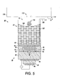
- FIGURE 5 depicts a first embodiment in which concepts of the present application may be implemented
- FIGURE 6A shows ejection of droplets using capillary action
- FIGURE 6B shows droplet evaporation and spontaneous fission of a droplet from the mist of droplets
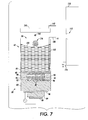
- FIGURE 7 illustrates another embodiment of concepts presented in the present application.
- FIGURE 8 illustrates a further embodiment of the present application where movement of the acoustic ejector and/or the well-plates are identified;
- FIGURE 9 illustrates an embodiment of the present invention using a plurality of ejectors in operational arrangement with a plurality of wells of the well-plate.
- FIGURE 10 sets forth a system to avoid contamination between wells of the well-plate.
- FIGURES 1-3 discuss providing a sample to a mass spectrometer, where a sample is introduced to the mass spectrometer, where the introduction may be by an electrospray technique (see Figure 2) or other introduction processes.
- the sample is in one instance provided via a liquid chromatographic process.
- FIGURE 4A depicted is a planar view of a multi-well plate 10 which may be used in connection with concepts of the present application. It is understood that well-plate 60 represents well-plates having any number of wells ( i . e ., reservoirs) 12.
- FIGURE 4B provides a portional cross-sectional view of well-plate 60. As shown in the cross-sectional portional view, the plurality of reservoirs 62 are spaced within the well plate, where the reservoirs 62 are connected within the overall well-plate via an upper interconnection surface 64.
- the reservoirs 62 which include a bottom surface 66, side walls 68 and a top aperture 70, are spaced from each other.
- Multi-well plates which may be used in connection with concepts of the present application can have any number of wells in any well arrangement, on any multi-well plate format or footprint.
- the wells are arranged in two-dimensional linear arrays such as shown in FIGURE 4A, and usually have between 96 and 384 wells.
- well plates with a larger number of wells such as 1536, 3456, and 9600, as well as other well plate sizes, may be used.
- Well volumes typically vary from 500 nanoliters or less to over 200 microliters, depending on well depth and cross-sectional area.
- Wells can be made in any cross-sectional shape (in plan view), including square, round and hexagonal, and in combinations thereof.
- Wells can be made in any cross-sectional shape (in vertical view), including shear vertical walls with flat or round bottoms, conical walls with flat or round bottom, and curved vertical walls with flat or round bottoms and combinations thereof.
- the materials for manufacturing the well plates are typically polymeric, since these materials lend themselves to mass manufacturing techniques. Polymeric materials can particularly facilitate plate manufacture by molding methods known in the art and developed in the future.
- One particular type of multi-well plate is a microtiter plate.
- FIGURE 5 depicts a first embodiment in which the concepts of the present application may be implemented. Shown in cross-section is a droplet emitter 80 in operational association with a well 62 of well-plate 60. It is to be understood the described droplet emitter is but one of various acoustic focused emitter designs which may be implemented in accordance with the concepts of the present application. More particularly, the specific placement of various components may be rearranged, and, as is well-known in the art, may still operate as an acoustic emitter. It is intended that the description be understood to also include these other arrangements.
- Droplet emitter 80 has a base substrate 82 with a transducer 84 interposed between two electrodes 86 on one surface and an acoustic lens 88 on an opposite surface. Attached to the same side of the base substrate 82 as the acoustic lens 88 is a top support 90 with a liquid cell 92 defined by sidewalls 94, which holds a low attenuation liquid 96. Supported by the top support 90 is an acoustically thin capping/acoustic coupling structure 98 which forms the top surface of the liquid cell 92 and seals in the low attenuation liquid 96. It is to be appreciated that capping/acoustic coupling structure 98 does not need to be permanently physically attached to the reservoir/well 62.
- capping/acoustic coupling structure 98 may at times only be acoustically coupled to the bottom of well 62.
- the capping/acoustic coupling structure 98 may be designed with a conformable polymer and/or an acoustic coupling material provided between capping/acoustic coupling structure 98 and well bottom 66, such as grease, or other appropriate substance.
- Droplet emitter 80 is located over, and acoustically coupled to, bottom surface 66 of well 62 of well-plate 60. As shown in FIGURE 5, the transducer 84, acoustic lens 88, and aperture 70 of well 62 are all axially aligned such that an acoustic wave produced by the transducer 84 will be focussed by its aligned acoustic lens 88 at approximately the free surface 100 of the emission fluid 102.
- a number of different acoustic lens types may be used dependant upon the ratio of aperture opening to height of the fluid contained in the well or reservoir.
- a number of different acoustic lens types may be used dependant upon the ratio of aperture opening to height of the fluid contained in the well or reservoir.
- a more weakly focused lens permits the projection of a focal point farther into a column of fluid where either the aperture or the plane of entry of the acoustic energy is limited in size.
- concepts of the present application may be implemented with both tightly focused beams having an F-number of 1 and more weakly focused lenses having F-numbers greater than 1, depending on the configuration of the well or reservoir.
- the minimum pulse width (t min ) is about 20 ⁇ sec, below which capillary mist droplets are generated. Minimum pulse width scales approximately as f -1 .
- a principal mound 104a When generating capillary wave-driven droplets, and as shown in FIGURE 6A, a principal mound 104a does not receive enough energy to eject a droplet. Instead, the top surface of the principal mound, and more particularly at the tip of the principal mound, becomes covered by capillary wave crests 104b, 104c, 104d, 104e (It is noted FIGURE 6A is not to scale as the capillary waves superimposed on top of the principal mound 104a are in the range of 1 :m across and the principal mound is about 300 um across.) These wave crests eject a mist corresponding to droplets 106a, 106b, 106c, 106d.
- each ejector transducer In order to generate capillary action droplets instead of focused, single ejection droplets, each ejector transducer provides shorter pulse widths at a higher peak power.
- Example pulse widths are on the order of 5 microseconds or less for an acoustic frequency of 5 MHz.
- the diameter of capillary generated droplets is similar in magnitude to the wavelength of capillary waves.
- capillary wave droplet systems the lower frequencies used allows more flexibility in materials and tolerances used to fabricate transducers and acoustic lenses used to form the array of droplet sources. For example, plastics are not as lossy at the lower frequencies. The lower loss levels would allow relatively inexpensive molded spherical lenses to be used as acoustic lenses.
- Use of capillary waves to generate a mist of droplets is discussed in commonly owned U.S. Application 09/739,988, entitled, "Using Capillary Wave Driven Droplets To Deliver A Pharmaceutical Product," hereby incorporated by reference.
- Analytical instrument 110 which in one embodiment is a mass spectrometer, is located opposite the aperture 70 of well 62, where an inlet 112 of mass spectrometer 110 is aligned substantially across from the point of mist/droplet ejection from aperture 70. It is to be appreciated an analytical instrument 110 may be any of the numerous mass spectrometers, different types of accelerators or any other instrument which would benefit from the concepts of the present application.
- a counter-electrode 114 is associated with the mass spectrometer. Use of electrodes 108 and 114 provide a voltage between fluid 102 and inlet 112 of mass spectrometer 110.
- the operation of the present system is intended to permit direct ejection of fluid 102 from well 62, in order to replace the emitter tip or syringe used in electrospray ionization processes.
- Emitter 80 in one embodiment, is operated to launch mist or spray of droplets 116 (i . e ., made up of droplets such as 106a-106d) during the time a voltage bias (108-114) exists between the fluid 102 and aperture 112 of mass spectrometer 110.
- emitter 80 may be operated to generate drops in accordance with "conventional" AIP droplets as described in the previously-cited Hadimioglu patent (U.S. Patent No. 5,565,113).
- the voltage bias produces an electric field used to accelerate the drops towards the mass spectrometer 110.
- emitter 80 is operated below the short pulse limit t (min) .
- This short pulse limit imparts acoustic energy sufficient to create a rising cone, created by the acoustic radiation pressure, on the free surface 100 of liquid 102. This results in the generation of capillary waves from which are emitted the small droplets, wherein thousands of these droplets may be generated per acoustic pulse.
- ejector 80 is operated below the short pulse limit, which is obtained by maintaining the pulse width sufficiently short in correspondence to the frequency of operation.
- the pulse width would be at or below approximately 5 microseconds to be below the short pulse limit.
- the short pulse limit scales with the drive frequency. Particularly, as the drive frequency is increased, the pulse width needs to become shorter to be under the short pulse limit.
- a droplet 130 which represents any one of the droplets of the mist of droplets 116 become smaller 132 due to droplet evaporation.
- the droplet evaporation may occur naturally or the system may include an evaporation arrangement such as known in the art.
- This droplet will have a sufficient charge so as to undergo a spontaneous fission, creating yet smaller droplets 134 as it propagates across the electric field. This spontaneous fission is repeated through the droplets' travel. It is worth noting that charging of the fluid is enhanced at the peaks of the capillary waves. Such enhancement occurs by the e-field enhancement at these peaks.
- mist/spray droplets on the order of 1 micron in diameter or smaller may be generated. While, for some operations 1 micron may be sufficiently sized , for other implementations the 1micron droplets may be too large.
- charging of the fluid surface by the application of voltage 108 is used to assist in the creation of the spontaneous fission for generation of smaller sized mist/spray droplets.
- FIGURE 7 illustrated is another embodiment of concepts presented the present application, where axis of the mass spectrometer 110 (or other analytical instrument) is substantially orthogonal to the mist ejection path as it is ejected from the aperture of the reservoir.
- This arrangement means the droplets of mist 116 cannot be moved directly into inlet 112.
- a charge plate 140 is provided in the path of mist116.
- Charge plate 140 includes a voltage source 142 which selectively generates a voltage (such as 5 k volts).
- the mist droplets 116 are accelerated towards plate 140 due to the voltage path generated between voltage source 108 (at approximately 5 Kv) and voltage source 142 (which at this initial period will be less than the voltage applied to the fluid.
- voltage source 142 is turned off and voltage source 114 of mass spectrometer 110 is turned on up (to around 5Kv).
- the switching on of voltage source 142 and the placing of voltage source 114 to common will occur when the droplets are at substantially a midpoint 144, within the path, and generally aligned to the aperture112 of mass spectrometer 110.
- This operation causes flight diversion of the mist droplets, so they are then accelerated to inlet 112.
- This embodiment teaches that ejector 80 and mass spectrometer 110 configuration does not require direct movement of mist 116 from ejector 80 to inlet 112.
- FIGURE 8 the present application may work in conjunction with a well-plate 60 having a plurality of wells 62.
- a transport 146 is used to move ejector 147 in the X, Y and Z directions to operationally engage a selected well of the well-plate.
- ejector 147 may be moved to another well to perform a next ejection operation.
- ejector 147 employs a coupling design which is different in its geometry than that shown in the previous figures. In this configuration, lens 148 focuses in a single coupling fluid 150, such as water or other appropriate substance into the bottom 66 of the well 62.
- ejector 147 may be stationary, and well-plate 60 may be associated with a transport 152 designed for moving well-plate 60 in the X, Y and Z directions. By this operation, it is well-plate 60 which is moved into an appropriate manner relative to ejector 147.
- This embodiment may be implemented both in the designs of FIGURES 6 and 7.
- FIG. 9 illustrated is a further embodiment wherein a plurality of ejectors 147a-147n are in operational arrangement with wells 62a-62n of the well-plate 60.
- the multiple ejectors 60a-60n and wells 62a-62n are moved together by transport 154. The movement places wells and corresponding ejectors at appropriate positions, such that when a mist is ejected it will be received at an inlet.
- a plurality of mass spectrometer 110 (not shown) maybe arranged so that drops from wells may be directed to different mass spectrometers during substantially the same time. This embodiment may be implemented both in the designs of FIGURES 6 and 7.
- a protection plate 160 may be provided on a transport system 162. Protection plate 160 will have an opening 164. When a particular well, such as well 60a of well-plate 60 is going to have a mist ejected, protection plate 160 will be moved whereby opening 164 is placed over well 60a until the ejection process is complete. By this design, the other wells of well-plate 60 are covered and will not be contaminated by the droplets emitting from well 60a. It is understood that in some instances protection plate 160 may be sufficiently sized and overlap the well-plate 60 such that placement of opening 164 at any of the wells will cover the remaining unused wells.
- protection plate 160 may be designed as separately controlled cover portions to minimize the size of the protection plate.
- An alternative embodiment provides controllable covers fitted over each individual well whereby upon operation, the cover would open and then close.
- a structure may be implemented, for example, using micro-electromechanical-structure (MEMS) covers such as 168.
- MEMS micro-electromechanical-structure
- a MEMS cover 168 may open for a short time interval allowing droplets to be ejected and remain closed during other periods.
- the cover whether a large area cover or a MEMS cover, will be electronically controlled such that the ejection of droplets causes the cover or protection plate to automatically retract out of the path of the ejected droplets.
- Such electronic control may be achieved by synchronizing a cover or protection plate control with the electrical impulse driving of the transducers.
- the present application teaches a system which includes an analytical device having an ionization chamber for analyzing an analyte molecule.
- This system also has a reservoir holding a fluid sample comprised of the analyte molecule, an ejector comprising an acoustic radiation generator for generating acoustic radiation, focusing means for focusing the acoustic radiation at a focal point near the surface of the fluid sample, a means for positioning the ejector in acoustic coupling relationship to the reservoir to eject a droplet of the fluid sample into the ionization chamber.
- the concepts set forth above may be accomplished through the use of either of the ejector types described. Further, the ejected fluid may be any of numerous types of biofluids.
Landscapes
- Chemical & Material Sciences (AREA)
- Analytical Chemistry (AREA)
- Other Investigation Or Analysis Of Materials By Electrical Means (AREA)
- Sampling And Sample Adjustment (AREA)
- Electron Tubes For Measurement (AREA)
- Automatic Analysis And Handling Materials Therefor (AREA)
Applications Claiming Priority (2)
| Application Number | Priority Date | Filing Date | Title |
|---|---|---|---|
| US329165 | 2002-12-24 | ||
| US10/329,165 US6827287B2 (en) | 2002-12-24 | 2002-12-24 | High throughput method and apparatus for introducing biological samples into analytical instruments |
Publications (2)
| Publication Number | Publication Date |
|---|---|
| EP1434251A2 true EP1434251A2 (fr) | 2004-06-30 |
| EP1434251A3 EP1434251A3 (fr) | 2005-04-06 |
Family
ID=32469027
Family Applications (1)
| Application Number | Title | Priority Date | Filing Date |
|---|---|---|---|
| EP03028643A Withdrawn EP1434251A3 (fr) | 2002-12-24 | 2003-12-15 | Méthode et dispositif d'introduction des échantillons biologiques dans une instrument analytique avec rendement élevé |
Country Status (3)
| Country | Link |
|---|---|
| US (1) | US6827287B2 (fr) |
| EP (1) | EP1434251A3 (fr) |
| JP (1) | JP2004205510A (fr) |
Families Citing this family (15)
| Publication number | Priority date | Publication date | Assignee | Title |
|---|---|---|---|---|
| US7208727B2 (en) * | 2003-01-14 | 2007-04-24 | Georgia Tech Research Corporation | Electrospray systems and methods |
| US7312440B2 (en) * | 2003-01-14 | 2007-12-25 | Georgia Tech Research Corporation | Integrated micro fuel processor and flow delivery infrastructure |
| US20060255261A1 (en) | 2005-04-04 | 2006-11-16 | Craig Whitehouse | Atmospheric pressure ion source for mass spectrometry |
| WO2007012000A2 (fr) * | 2005-07-19 | 2007-01-25 | Steven Clyde Hill | Classificateur de particules presentes dans un liquide utilisant un ejecteur de gouttelettes a grand orifice |
| US7958887B2 (en) * | 2006-03-10 | 2011-06-14 | Aradigm Corporation | Nozzle pore configuration for intrapulmonary delivery of aerosolized formulations |
| JP4656051B2 (ja) * | 2006-12-15 | 2011-03-23 | パナソニック電工株式会社 | 静電霧化装置 |
| GB201120141D0 (en) * | 2011-11-22 | 2012-01-04 | Micromass Ltd | Low cross-talk (cross-contamination) fast sample delivery system based upon acoustic droplet ejection |
| GB2535265B (en) * | 2014-10-17 | 2017-04-12 | Micromass Ltd | Ion source |
| US9939352B2 (en) * | 2014-10-17 | 2018-04-10 | Labcyte, Inc. | Method and system for determining the concentration of an analyte in a fluid sample |
| US10325768B1 (en) | 2015-09-03 | 2019-06-18 | Labcyte Inc. | Focused acoustic radiation for rapid sequential ejection of subwavelength droplets |
| CN122193614A (zh) * | 2017-11-22 | 2026-06-12 | 拉伯塞特股份有限公司 | 使用连续流动采样探针对分析仪器进行声学加载的系统和方法 |
| ES3058041T3 (en) | 2017-12-11 | 2026-03-06 | Melbourne Inst Tech | Apparatus for addressing wells within a microarray plate |
| JP6932237B2 (ja) * | 2018-02-27 | 2021-09-08 | シャープ株式会社 | 霧化装置および調湿装置 |
| AU2019370221B2 (en) | 2018-10-29 | 2023-05-11 | Labcyte Inc. | Acoustic droplet ejection of non-Newtonian fluids |
| CA3127492C (fr) * | 2019-02-01 | 2023-10-03 | Labcyte Inc. | Concentration acoustique, transfert et analyse d'echantillons contenant des particules |
Citations (1)
| Publication number | Priority date | Publication date | Assignee | Title |
|---|---|---|---|---|
| US20020073989A1 (en) * | 2000-12-18 | 2002-06-20 | Xerox Corporation | Using capillary wave driven droplets to deliver a pharmaceutical product |
Family Cites Families (30)
| Publication number | Priority date | Publication date | Assignee | Title |
|---|---|---|---|---|
| DE3013620A1 (de) * | 1979-05-25 | 1980-12-04 | Hewlett Packard Co | Probeneingabevorrichtung fuer massenspektrometer |
| JPS59111053A (ja) * | 1982-12-17 | 1984-06-27 | Jeol Ltd | 液体試料導入装置 |
| US4748461A (en) * | 1986-01-21 | 1988-05-31 | Xerox Corporation | Capillary wave controllers for nozzleless droplet ejectors |
| US4751529A (en) | 1986-12-19 | 1988-06-14 | Xerox Corporation | Microlenses for acoustic printing |
| US4782350A (en) * | 1987-10-28 | 1988-11-01 | Xerox Corporation | Amorphous silicon varactors as rf amplitude modulators and their application to acoustic ink printers |
| US4959674A (en) * | 1989-10-03 | 1990-09-25 | Xerox Corporation | Acoustic ink printhead having reflection coating for improved ink drop ejection control |
| US5194880A (en) | 1990-12-21 | 1993-03-16 | Xerox Corporation | Multi-electrode, focused capillary wave energy generator |
| US5259254A (en) * | 1991-09-25 | 1993-11-09 | Cetac Technologies, Inc. | Sample introduction system for inductively coupled plasma and other gas-phase, or particle, detectors utilizing ultrasonic nebulization, and method of use |
| US5191354A (en) * | 1992-02-19 | 1993-03-02 | Xerox Corporation | Method and apparatus for suppressing capillary waves in an ink jet printer |
| US5629724A (en) * | 1992-05-29 | 1997-05-13 | Xerox Corporation | Stabilization of the free surface of a liquid |
| US5232114A (en) * | 1992-08-10 | 1993-08-03 | Crown Cork & Seal Company, Inc. | Full-open convenience closure |
| US5669971A (en) * | 1994-04-06 | 1997-09-23 | Specialty Coating Systems, Inc. | Selective coating apparatus |
| EP0682988B1 (fr) * | 1994-05-18 | 2001-11-14 | Xerox Corporation | Déposition acoustique de couches de matériaux |
| US5565113A (en) | 1994-05-18 | 1996-10-15 | Xerox Corporation | Lithographically defined ejection units |
| US5520715A (en) * | 1994-07-11 | 1996-05-28 | The United States Of America As Represented By The Administrator Of The National Aeronautics And Space Administration | Directional electrostatic accretion process employing acoustic droplet formation |
| US6294779B1 (en) * | 1994-07-11 | 2001-09-25 | Agilent Technologies, Inc. | Orthogonal ion sampling for APCI mass spectrometry |
| JP3415682B2 (ja) * | 1994-08-10 | 2003-06-09 | 株式会社日立製作所 | キャピラリー電気泳動・質量分析計 |
| US6063338A (en) | 1997-06-02 | 2000-05-16 | Aurora Biosciences Corporation | Low background multi-well plates and platforms for spectroscopic measurements |
| JP3694598B2 (ja) * | 1998-10-14 | 2005-09-14 | 株式会社日立製作所 | 大気圧イオン化質量分析装置 |
| DE1005917T1 (de) * | 1998-12-01 | 2001-01-11 | Microflow Engineering S.A., Neuenburg/Neuchatel | Inhalator mit Ultraschallzerstäuber dessen Sprühöffnungen den Maximalamplituden eines stehenden Wellenmusters überlagert sind |
| US6134291A (en) | 1999-07-23 | 2000-10-17 | Xerox Corporation | Acoustic ink jet printhead design and method of operation utilizing flowing coolant and an emission fluid |
| JP2002107344A (ja) * | 2000-10-04 | 2002-04-10 | Shimadzu Corp | 液体クロマトグラフ質量分析装置 |
| US6666541B2 (en) * | 2000-09-25 | 2003-12-23 | Picoliter Inc. | Acoustic ejection of fluids from a plurality of reservoirs |
| US6548308B2 (en) * | 2000-09-25 | 2003-04-15 | Picoliter Inc. | Focused acoustic energy method and device for generating droplets of immiscible fluids |
| US8122880B2 (en) | 2000-12-18 | 2012-02-28 | Palo Alto Research Center Incorporated | Inhaler that uses focused acoustic waves to deliver a pharmaceutical product |
| US7121275B2 (en) | 2000-12-18 | 2006-10-17 | Xerox Corporation | Method of using focused acoustic waves to deliver a pharmaceutical product |
| US6603118B2 (en) * | 2001-02-14 | 2003-08-05 | Picoliter Inc. | Acoustic sample introduction for mass spectrometric analysis |
| ATE476751T1 (de) * | 2001-03-29 | 2010-08-15 | Wisconsin Alumni Res Found | Piezoelektrisch geladene tröpfchenquelle |
| US6416164B1 (en) | 2001-07-20 | 2002-07-09 | Picoliter Inc. | Acoustic ejection of fluids using large F-number focusing elements |
| JP2003331777A (ja) * | 2002-05-16 | 2003-11-21 | Hitachi High-Technologies Corp | 質量分析装置 |
-
2002
- 2002-12-24 US US10/329,165 patent/US6827287B2/en not_active Expired - Fee Related
-
2003
- 2003-12-15 EP EP03028643A patent/EP1434251A3/fr not_active Withdrawn
- 2003-12-18 JP JP2003421586A patent/JP2004205510A/ja active Pending
Patent Citations (1)
| Publication number | Priority date | Publication date | Assignee | Title |
|---|---|---|---|---|
| US20020073989A1 (en) * | 2000-12-18 | 2002-06-20 | Xerox Corporation | Using capillary wave driven droplets to deliver a pharmaceutical product |
Also Published As
| Publication number | Publication date |
|---|---|
| US20040118953A1 (en) | 2004-06-24 |
| JP2004205510A (ja) | 2004-07-22 |
| EP1434251A3 (fr) | 2005-04-06 |
| US6827287B2 (en) | 2004-12-07 |
Similar Documents
| Publication | Publication Date | Title |
|---|---|---|
| US6827287B2 (en) | High throughput method and apparatus for introducing biological samples into analytical instruments | |
| US6797945B2 (en) | Piezoelectric charged droplet source | |
| US5905258A (en) | Hybrid ion mobility and mass spectrometer | |
| US6649907B2 (en) | Charge reduction electrospray ionization ion source | |
| JP4023738B2 (ja) | 遅延引き出し付きタンデム飛行時間型質量分析計および使用方法 | |
| US6812455B2 (en) | Method and apparatus for MALDI analysis | |
| US6972407B2 (en) | Method and apparatus for electrospray augmented high field asymmetric ion mobility spectrometry | |
| EP1676291B1 (fr) | Spectrometrie de masse maldi/tof a mobilite ionique utilisant une cellule de mobilite qui alterne les zones de champ electrique fort et faible | |
| US6974957B2 (en) | Ionization device for aerosol mass spectrometer and method of ionization | |
| CA2090616C (fr) | Appareil et methode d'analyse de traces | |
| US7109479B2 (en) | Method and system for mass spectroscopy | |
| US20100181473A1 (en) | Method and apparatus for the analysis of samples |
Legal Events
| Date | Code | Title | Description |
|---|---|---|---|
| PUAI | Public reference made under article 153(3) epc to a published international application that has entered the european phase |
Free format text: ORIGINAL CODE: 0009012 |
|
| AK | Designated contracting states |
Kind code of ref document: A2 Designated state(s): AT BE BG CH CY CZ DE DK EE ES FI FR GB GR HU IE IT LI LU MC NL PT RO SE SI SK TR |
|
| AX | Request for extension of the european patent |
Extension state: AL LT LV MK |
|
| RAP1 | Party data changed (applicant data changed or rights of an application transferred) |
Owner name: THE SCRIPPS RESEARCH INSTITUTE Owner name: PALO ALTO RESEARCH INCORPORATED |
|
| RAP1 | Party data changed (applicant data changed or rights of an application transferred) |
Owner name: THE SCRIPPS RESEARCH INSTITUTE Owner name: PALO ALTO RESEARCH CENTER INCORPORATED |
|
| PUAL | Search report despatched |
Free format text: ORIGINAL CODE: 0009013 |
|
| AK | Designated contracting states |
Kind code of ref document: A3 Designated state(s): AT BE BG CH CY CZ DE DK EE ES FI FR GB GR HU IE IT LI LU MC NL PT RO SE SI SK TR |
|
| AX | Request for extension of the european patent |
Extension state: AL LT LV MK |
|
| RIC1 | Information provided on ipc code assigned before grant |
Ipc: 7G 01N 1/00 B Ipc: 7H 01J 49/04 A |
|
| 17P | Request for examination filed |
Effective date: 20050920 |
|
| AKX | Designation fees paid |
Designated state(s): DE FR GB |
|
| 17Q | First examination report despatched |
Effective date: 20120313 |
|
| STAA | Information on the status of an ep patent application or granted ep patent |
Free format text: STATUS: THE APPLICATION IS DEEMED TO BE WITHDRAWN |
|
| 18D | Application deemed to be withdrawn |
Effective date: 20120724 |