EP1434256A2 - Conteneur de plaquettes fines - Google Patents
Conteneur de plaquettes fines Download PDFInfo
- Publication number
- EP1434256A2 EP1434256A2 EP03029812A EP03029812A EP1434256A2 EP 1434256 A2 EP1434256 A2 EP 1434256A2 EP 03029812 A EP03029812 A EP 03029812A EP 03029812 A EP03029812 A EP 03029812A EP 1434256 A2 EP1434256 A2 EP 1434256A2
- Authority
- EP
- European Patent Office
- Prior art keywords
- supporting
- container body
- plate
- slotted
- thin plate
- Prior art date
- Legal status (The legal status is an assumption and is not a legal conclusion. Google has not performed a legal analysis and makes no representation as to the accuracy of the status listed.)
- Granted
Links
Images


Classifications
-
- H—ELECTRICITY
- H10—SEMICONDUCTOR DEVICES; ELECTRIC SOLID-STATE DEVICES NOT OTHERWISE PROVIDED FOR
- H10P—GENERIC PROCESSES OR APPARATUS FOR THE MANUFACTURE OR TREATMENT OF DEVICES COVERED BY CLASS H10
- H10P72/00—Handling or holding of wafers, substrates or devices during manufacture or treatment thereof
- H10P72/50—Handling or holding of wafers, substrates or devices during manufacture or treatment thereof for positioning, orientation or alignment
-
- H—ELECTRICITY
- H10—SEMICONDUCTOR DEVICES; ELECTRIC SOLID-STATE DEVICES NOT OTHERWISE PROVIDED FOR
- H10P—GENERIC PROCESSES OR APPARATUS FOR THE MANUFACTURE OR TREATMENT OF DEVICES COVERED BY CLASS H10
- H10P72/00—Handling or holding of wafers, substrates or devices during manufacture or treatment thereof
- H10P72/10—Handling or holding of wafers, substrates or devices during manufacture or treatment thereof using carriers specially adapted therefor, e.g. front opening unified pods [FOUP]
- H10P72/19—Handling or holding of wafers, substrates or devices during manufacture or treatment thereof using carriers specially adapted therefor, e.g. front opening unified pods [FOUP] closed carriers
- H10P72/1914—Handling or holding of wafers, substrates or devices during manufacture or treatment thereof using carriers specially adapted therefor, e.g. front opening unified pods [FOUP] closed carriers characterised by locking systems
-
- H—ELECTRICITY
- H10—SEMICONDUCTOR DEVICES; ELECTRIC SOLID-STATE DEVICES NOT OTHERWISE PROVIDED FOR
- H10P—GENERIC PROCESSES OR APPARATUS FOR THE MANUFACTURE OR TREATMENT OF DEVICES COVERED BY CLASS H10
- H10P72/00—Handling or holding of wafers, substrates or devices during manufacture or treatment thereof
- H10P72/10—Handling or holding of wafers, substrates or devices during manufacture or treatment thereof using carriers specially adapted therefor, e.g. front opening unified pods [FOUP]
- H10P72/19—Handling or holding of wafers, substrates or devices during manufacture or treatment thereof using carriers specially adapted therefor, e.g. front opening unified pods [FOUP] closed carriers
- H10P72/1918—Handling or holding of wafers, substrates or devices during manufacture or treatment thereof using carriers specially adapted therefor, e.g. front opening unified pods [FOUP] closed carriers characterised by coupling elements, kinematic members, handles or elements to be externally gripped
-
- H—ELECTRICITY
- H10—SEMICONDUCTOR DEVICES; ELECTRIC SOLID-STATE DEVICES NOT OTHERWISE PROVIDED FOR
- H10P—GENERIC PROCESSES OR APPARATUS FOR THE MANUFACTURE OR TREATMENT OF DEVICES COVERED BY CLASS H10
- H10P72/00—Handling or holding of wafers, substrates or devices during manufacture or treatment thereof
- H10P72/10—Handling or holding of wafers, substrates or devices during manufacture or treatment thereof using carriers specially adapted therefor, e.g. front opening unified pods [FOUP]
- H10P72/19—Handling or holding of wafers, substrates or devices during manufacture or treatment thereof using carriers specially adapted therefor, e.g. front opening unified pods [FOUP] closed carriers
- H10P72/1921—Handling or holding of wafers, substrates or devices during manufacture or treatment thereof using carriers specially adapted therefor, e.g. front opening unified pods [FOUP] closed carriers characterised by substrate supports
Definitions
- the present invention relates to a thin plate supporting container for housing, storing, and transporting thin plates such as semiconductor wafers, storage disks, or liquid crystal glass substrates.
- a thin plate supporting container is generally constructed by a container body and a lid unit for closing the upper opening of the container body.
- slotted plates are provided on opposite side walls, and a plurality of thin plates such as semiconductor wafers are supported between the slotted plates.
- the slotted plates are detachably supported in the container body. Specifically, a supporting hole is opened on the slotted plate side and a supporting projection is provided on the container body side. By the supporting hole and the supporting projection, the slotted plates are detachably supported in the container body.
- a supporting hole is opened on a slotted plate (thin plate supporting member) side and a supporting projection to be fit in the supporting hole is provided on the container body side.
- the sets each consisting of the supporting hole and the supporting projection are provided in three positions.
- the slotted plate Since the sets of the supporting hole and the supporting projection are provided in three positions, the slotted plate is not deflected. A mode of providing the sets only in two positions at both ends of the slotted plate is also possible. In this case, however, since the supporting hole and the supporting projection have a circular shape and can rotate in a state where they fit with each other, the slotted plates may be deflected.
- the position in the deep portion of the slotted plate may be slightly deviation.
- semiconductor wafers are supported in the deep portions of the slotted plates. If there is a positional deviation in the deep portions of the slotted plates, the position of supporting a semiconductor wafer is deviated in the thin plate supporting container.
- a plurality of plate pieces constructing the slotted plate are formed so as to curve along the periphery of a semiconductor wafer close to an inlet/outlet port of semiconductor wafers.
- an inlet/outlet port side of a plate piece largely extends toward the semiconductor wafer side, so that the possibility that a semiconductor wafer to be supplied/taken out comes into contact with the plate piece is high.
- the inlet/outlet port side of the plate piece has to be widened to the container body side.
- the semiconductor wafer supporting positions are on the deep side and an intermediate position. There is no support near the inlet/outlet port, so that supporting is unstable.
- the thin plate supporting container is tall.
- the gap between the bottom of the box and the bottom of the thin plate supporting container is small. Accordingly, an amount of cushioning which is put between the bottom of the box and the bottom of the thin plate container becomes small.
- the amount of cushioning is larger.
- a top flange and a handle are detachably attached to the thin plate supporting container.
- an external force which is strong in the direction of pulling out the top flange or handle is applied by an abnormal shock of a fall of the thin plate supporting container or the like, there is the possibility that a locking pawl or the like comes off and the top flange or the like drops.
- a thin plate pressing member On the back side of the lid unit, a thin plate pressing member is provided. Fitting grooves are formed in the thin plate pressing member. Semiconductor wafers are supported by being fit in the fitting grooves one by one.
- the fitting groove is formed in a V shape, the angle of the V-shaped fitting groove is usually an obtuse angle, and the periphery of a semiconductor wafer is lightly caught in the fitting groove.
- the thin plate pressing member is constructed by a number of pressing bands disposed in parallel for supporting semiconductor wafers one by one at predetermined intervals, and the periphery of a semiconductor wafer is supported by being fit in a fitting groove formed in the pressing band. In this case, if a semiconductor wafer comes off from the fitting groove in the pressing band, the semiconductor wafer may be fit in the gap between the pressing bands.
- positioning means for positioning the thin plate supporting container.
- the positioning means is constructed by three fitting grooves provided at almost equal intervals. When positioning projections on a base stand side fit in the fitting grooves, the container body is accurately positioned. Since the fitting grooves are made of the same material as that of the thin plate supporting container, in a state where the positioning projections are fit in the fitting grooves, the positioning projections do not slide smoothly. There is a case that the positioning projection stops midway in the fitting groove and accurate positioning cannot be performed.
- the present invention has been achieved in consideration of the above problems and its object is to provide a thin plate supporting container capable of accurately, reliably, and stably supporting a thin plate, to/from which a lid unit, a top end, and the like can be attached/detached reliably and easily, and which can be accurately positioned.
- a thin plate supporting container comprising by a container body for housing therein a plurality of thin plates, a lid unit for closing the container body, and slotted plates provided on side walls facing each other in the container body for supporting the thin plates housed on the inside from both sides, including an upper fitting portion for supporting an upper portion of the slotted plate to the container body side, and a lower fitting portion for supporting a lower portion of the slotted plate to the container body side, the upper fitting portion including an upper fitting piece provided at each of at least both ends of each of the side walls facing each other in the container body, and an upper receiving piece provided in a position facing the upper fitting piece, of the slotted plate, the upper fitting piece having a contact face having a flat plane shape which comes into contact with the slotted plate side to thereby position the slotted plate in the front/rear direction while suppressing swing of the slotted plate, and a supporting face for supporting the contact face in a state where the contact face is in contact with the slotted plate side, and the upper
- the slotted plate is positioned in the front/rear direction while suppressing swing of the slotted plate.
- deformation such as a deflection of the slotted plate is prevented and the slotted plate can be supported in an accurate position.
- a thin plate supporting container comprising a container body for housing therein a plurality of thin plates, a lid unit for closing the container body, and slotted plates provided on side walls facing each other in the container body for supporting the thin plates housed on the inside from both sides, including an upper fitting portion for supporting an upper portion of the slotted plate to the container body side, and a lower fitting portion for supporting a lower portion of the slotted plate to the container body side, and the lower fitting portion having a vertical-direction positioning means for positioning the slotted plate in the vertical direction, horizontal-direction positioning means for performing positioning in the horizontal direction, and a front/rear-direction positioning means for performing positioning in the front/rear direction.
- the slotted plate is positioned in the vertical direction by the vertical-direction positioning means.
- the slotted plate is positioned in the horizontal direction by the horizontal-direction positioning means.
- the slotted plate is positioned in the front/rear direction by the front/rear-direction positioning means. In cooperation with the upper fitting portion, the slotted plate can be accurately positioned and fixed.
- the vertical-direction supporting piece fits with the lower portion of the slotted plate and comes into contact with the lower end of the slotted plate, thereby accurately positioning the slotted plate in the vertical direction.
- the horizontal-direction positioning means has a notch formed in a lower portion of the slotted plate, and a horizontal-direction supporting piece which is provided in a lower portion of each of side walls facing each other in the container body, fits with the notch in the lower portion of the slotted plate, and performs positioning in the horizontal direction of the slotted plate.
- the horizontal-direction supporting piece fits with the notch, thereby accurately positioning the slotted plate in the horizontal direction.
- the front/rear direction positioning means has a front/rear direction supporting piece which is provided so as to extend from the lower portion of the slotted plate to a back side of the slotted plate, and contacts with the lower portion of a side wall face of the container body, thereby positioning the slotted plate in the front/rear direction.
- the front/rear-direction supporting piece comes into contact with the lower portion of the side wall face of the container body, thereby accurately positioning the slotted plate in the front/rear direction.
- a stopper for stopping disengagement from the above of the slotted plate by being locked to the container body side is provided in a lower portion of the slotted plate.
- the slotted plate is supported so as not to be disengaged from the above.
- a thin plate supporting container comprising a container body for housing therein a plurality of thin plates, a lid unit for closing the container body, and slotted plates provided on side walls facing each other in the container body and supporting the thin plates housed on the inside from both sides, wherein the slotted plate is constructed by arranging a plurality of plate pieces for supporting the plurality of thin plates one by one, the plate piece is extended from an inner side of the container body to an outlet/inlet port of the thin plate and is formed so that a portion from the inner side to an intermediate position is curved along the periphery of the thin plate and a portion from the intermediate position to the outlet/inlet port is along the container body side, on the inner side and the outlet/inlet port side in the plate piece, thin plate supporting projections for supporting the thin plates are provided, and the thin plate supporting projection on the outlet/inlet port side is provided around an intersecting point of an inner periphery of the plate piece and the periphery of the thin plate.
- a thin plate is supported by the thin plate supporting projections provided on the inner side of the plate piece and around he intersection point of the inner periphery of the plate piece and the periphery of the thin plate, so that the thin plate can be stably supported.
- a thin plate supporting container comprising a container body for housing therein a plurality of thin plates, a lid unit for closing the container body, and slotted plates provided on side walls facing each other in the container body and supporting the thin plates housed on the inside from both sides, wherein a gasket is provided between the lid unit and the container body, the gasket has a base end supporting portion for supporting the whole by being fit to the lid unit side or container body side, and a contact portion formed so as to extend from the base end supporting portion, the contact portion is formed by being expanded from the base end supporting portion into a flange shape, making its intermediate portion swollen upward, and making an outer periphery folded downward, and the intermediate portion is pressed against the lid unit side or the body side in a state where the periphery is in contact with the container body side or the lid unit side, thereby making the periphery closely attached to the container body side or the lid unit side by elastic force of the contact portion.
- the intermediate portion of the contact portion is formed by making its intermediate portion swollen upward and folding an outer periphery downward.
- the periphery is closely attached to the container body side or the lid unit side by elastic force of the contact portion. Consequently, even when the gasket is deflected, the periphery can be closely attached to the container body side or the lid unit side with reliability.
- the thin plate supporting container according to the eighth invention further includes: a seal piece which is provided on the inner side of an upper surface of a base end supporting portion of the gasket, is extended upward, and comes into contact with the lid unit side or container body side; and an annular groove provided on the outer side of the seal piece and absorbing elastic deformation of the seal piece.
- the seal piece is in contact with the lid unit side or the container body side, and elastic deformation by the contact of the seal piece is absorbed by the annular groove.
- a thin plate supporting container comprising a container body for housing therein a plurality of thin plates, a lid unit for closing the container body, and slotted plates provided on side walls facing each other in the container body and supporting the thin plates housed on the inside from both sides, wherein a bottom plate of the container body is set so that a gap between the bottom plate and the lower end of the thin plate housed in the container body is set minimum, enough to absorb shock.
- height of the container body is reduced only by an amount corresponding to reduction in the gap between the bottom plate of the container body and the lower end of the thin plate housed in the container body.
- the size of the thin plate supporting container can be reduced. Consequently, when packed, cushioning between the bottom of the thin plate supporting container and a packing box can be increased, and impact absorbing capability in the case of an impact of a fall or the like can be largely improved.
- a thin plate supporting container comprising a container body for housing therein a plurality of thin plates, a lid unit for closing the container body, and slotted plates provided on side walls facing each other in the container body and supporting the thin plates housed on the inside from both sides, wherein an attaching/detaching mechanism is provided for detachably attaching any one of a top flange for a carrying mechanism and a handle held by the user or both to the container body, the attaching/detaching mechanism has a sliding and supporting means for slidably supporting the container body and the top flange or handle so that the two members are slidable on each other, and locking means for locking the two members slidably supported by the sliding and supporting means so as not to be deviated from each other, the sliding and supporting means includes a supporting portion provided for one of members and a sliding portion which is provided for the other member and is to be inserted into the supporting portion from the front side to the inner side, the locking means has
- the supporting bar portion is formed so as to extend to the other-side member and to the front side of the sliding and supporting means. Therefore, in the case where a strong force is applied in the direction of making the top flange or the like come off, by the support of the supporting bar portion, disengagement of the top flange or the like is prevented. Thus, even if a strong impact is given to the top flange or the like, the top flange or the like does not come off.
- the contact portion of the locking pawl is provided on the side of the other-side member than the base end portion of the supporting bar portion.
- the contact portion of the locking pawl is provided on the side of the other-side member than the base end portion of the supporting bar portion, the contact portion is pressed strongly against the locking projection. Consequently, even if a strong force is applied by an impact or the like, the contact portion does not come off from the locking projection.
- the thin plate supporting container in the thin plate supporting container according to the twelfth or thirteenth aspect, two supporting portions and two sliding portions of the sliding and supporting means are provided in parallel, and each of the interval between the supporting portions and the interval between the sliding portions is set to be small on the front side and to be large on the inner side.
- the sliding portion can be easily fit in the supporting portion.
- the thin plate supporting container according to any of the twelfth to fourteenth inventions further includes guide rails for guiding two members supported by the sliding and supporting means so as to slide and performing positioning in a direction orthogonal to the sliding direction.
- the two members supported by the sliding and supporting means can be easily attached/detached.
- a thin plate supporting container comprising a container body for housing therein a plurality of thin plates, a lid unit for closing the container body, and slotted plates provided on side walls facing each other in the container body and supporting the thin plates housed on the inside from both sides, wherein the lid unit is provided with a latch mechanism for fixing the lid unit to the container body, the latch mechanism is constructed by a first arm locked to the container body side to fix the lid unit to the container body, and a second arm swingably supported by the lid unit and swingably supporting the first arm, the first arm is constructed by a locking pawl which is provided in a base end portion of the first arm and comes into contact with the container body side, and a grip which is provided at a tip portion and is positioned in a side of the lid unit in a state where the first and second arms swing to the limit, and the second arm swings to a position where the locking pawl of the base end portion of the first arm does not come into contact with the container body in
- the user grips the grip of the first arm to lift the lid unit up and covers the container body with the lid unit from above.
- the grip is positioned on a side of the lid unit in a state where the first and second arms swing to each limit, so that the user can easily lift the lid unit and cover the container body with the lid unit.
- the grip is pushed downward.
- the locking pawl in the base end portion of the first arm comes into contact with the container body side and the lid unit is fixed to the container body.
- the user grips the grips of the first arms and pulls the grips to the opposite sides.
- the locking pawl in the base end portion of the first arm is detached from the container body side and the lid unit is disengaged.
- the user still grips the grips to lift the lid unit.
- the locking pawl in the base end portion swings to a position in which it does not come into contact with the container body in a state where the second arm makes the first arm swing to the limit. Consequently, the lid unit can be easily detached. In such a manner, the lid unit can be easily attached/detached.
- the first arm is open up to 90° with respect to the second arm and the second arm is open up to 35° with respect to the container body.
- the grip is supported in a side of the lid unit and is in a position at which the grip is easily gripped, and is open to a position where the locking pawl comes not come into contact with the container body.
- a thin plate supporting container comprising a container body for housing therein a plurality of thin plates, a lid unit for closing the container body, and slotted plates provided on side walls facing each other in the container body for supporting the thin plates housed on the inside from both sides, wherein a thin plate pressing member is provided on the back face of the lid unit, the thin plate pressing member for supporting thin plates by pressing an upper portion of a thin plate housed in the container body when the lid unit is attached to the container body, fitting grooves in each of which the thin plate is fit and supported are provided for the thin plate pressing member, the fitting groove being formed at an acute angle so as to catch the periphery of the thin plate.
- the fitting groove for supporting a thin plate is provided for the thin plate pressing member and is formed at an acute angle. Consequently, even when a strong impact is given to the thin plate supporting container, the periphery of the thin plate is caught by the fitting groove formed at an acute angle, rotation of the thin plate is prevented, and the thin plate can be reliably supported.
- a thin plate supporting container comprising a container body for housing therein a plurality of thin plates, a lid unit for closing the container body, and slotted plates provided on side walls facing each other in the container body and supporting the thin plates housed on the inside from both sides, wherein a thin plate pressing member is provided on the back face of the lid unit, the thin plate pressing member for supporting thin plates by pressing an upper portion of a thin plate housed in the container body when the lid unit is attached to the container body, the thin plate pressing member has a number of pressing bands which are arranged in parallel, comes into contact with the periphery of the thin plate, and supports the thin plates at predetermined intervals one by one, and the pressing bands are formed in a wave shape along the peripheries of the thin plates.
- the pressing bands are formed along the peripheries of thee thin plates, even when the thin plate is displaced, it does not enter the gap between the pressing bands.
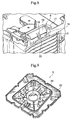
- a thin plate supporting container comprising a container body for housing therein a plurality of thin plates, a lid unit for closing the container body, and slotted plates provided on side walls facing each other in the container body for supporting the thin plates housed on the inside from both sides, wherein body positioning means for positioning the whole container body is provided on the bottom of the container body disposed transversely, and the body positioning means includes V-shaped groove plate pieces constructing V-shaped grooves provided in three positions in three directions on the bottom of the container body, and supporting stands for supporting the V-shaped groove plate pieces.
- the V-shaped groove plate piece is attached as a separate member to the supporting stand of the body positioning means, the V-shaped groove plate piece made of a material suited to the material of the projection on the other side can be easily attached.
- the V-shaped groove plate piece is made of a material having low surface friction resistance.
- the V-shaped groove plate piece is detachably attached to the supporting stand.
- the V-shaped groove plate piece since the V-shaped groove plate piece is detachably attached, the V-shaped groove plate piece can be easily replaced in accordance with the material of the projection on the other side.
- a thin plate supporting container of the present invention is suitable as a container used in processes of housing, storing, transporting, and producing thin plates such as semiconductor wafers, storage disks, and liquid crystal glass substrates.
- a thin film supporting container for housing semiconductor wafers will be described as an example.
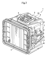
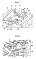
- a thin plate supporting container 1 has, as shown in FIGS. 1 to 3, a container body 2 for housing therein a plurality of semiconductor wafers S (refer to Fig. 16), two slotted plates 3 provided on opposite side walls in the container body 2 and supporting the housed semiconductor wafers S from both sides, a lid unit 4 for closing an opening 2F of the container body 2, a top flange 5 held by an arm of a transporting apparatus (not shown) , and a handle 6 for carry which is gripped by the user when the user carries the thin plate supporting container 1.
- the container body 2 is formed in an almost cube shape.
- the container body 2 comprises four side walls 2A, 2B, 2C, and 2D serving as peripheral walls and a bottom plate 2E when the container body 2 is set longitudinally (in a state where the bottom plate 2E is down), and an opening 2F is provided at the top of the container body 2.
- Ribs 9 for reinforcement and the like are provided for each of the side walls 2A, 2B, 2C, and 2D.
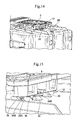
- top flange 5 is detachably attached by an attaching/detaching mechanism 12 to the outside of the side wall 2B serving as the ceiling transversely.
- attaching/detaching mechanism 12 is provided to the outside of the side wall 2B serving as the ceiling transversely.
- the handles 6 for carry are detachably attached.
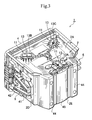
- the body positioning means 11 is constructed by, as shown in Fig. 3, three V-shaped fitting grooves 13.
- the fitting grooves 13 are a first fitting groove 13A aligned in the vertical direction of the container body 2 and second and third fitting grooves 13B and 13C each inclined by an angle (almost 60 degrees) from the vertical direction of the container body 2.
- the three grooves 13 are set to have high dimensional precision in accordance with a standard.
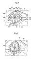
- Each of the fitting grooves 13 is constructed by a V-shaped groove plate piece 15 and a supporting stand 16.
- the V-shaped groove plate piece 15 is a member as a component of the fitting groove 13.
- the V-shaped groove plate piece 15 is constructed by a frame 17, inclined plates 18, and locking pawls 19.
- the frame 17 is a member for supporting the inclined plate 18 and the locking pawl 19.
- the frame 17 is formed in a rectangular shape so as to fit with a notch 21C for fitting of the supporting stand 16 which will be described later.
- supporting plate fitting notches 17A which fit with end portion supporting plates 22 of the supporting stand 16 which will be described later to stably support the whole container are provided.
- the inclined plates 18 are members serving as inclined surfaces of the fitting groove 13. Two inclined plates 18 are provided for one frame 17. In a state where the base end portion of each of the inclined plates 18 is fixed to the frame 17, the inclined plates 18 extend downward to the inside.
- the thickness of the inclined plate 18 is set in relation with the supporting stand 16 so that the upper surface (the upper surface in Fig.
- the V-shaped groove plate piece 15 is made of a material having low surface friction resistance, so that a fitting projection of a mounting stand used in the semiconductor fabricating process slides smoothly to perform accurate positioning of the thin plate supporting container 1.
- An example of the material is PBT.
- the locking pawls 19 are members for fixing the V-shaped groove plate piece 15 to the supporting stand 16.
- the locking pawls 19 extend from the center portion of the inclined plate 18 downward to the inside.
- the tip of the locking pawl 19 is folded back to the perpendicular direction, and a nail portion 19A at the tip of the locking pawl 19 is locked by a locking projection 23 of the supporting stand 16 which will be described later.
- the V-shaped groove plate piece 15 is detachably attached to the supporting stand 16.
- the V-shaped groove plate piece 15 of a material (material having low surface friction resistance) matched with the material of the fitting projection of the mounting stage used in the semiconductor fabricating process is attached. It makes the fitting projection on the other side easily slide in the V-shaped groove plate piece 15 to perform accurate positioning.
- the supporting stand 16 is a member for supporting the V-shaped groove plate piece 15.
- the supporting stand 16 is constructed by an inclination supporting plate 21, an end-portion supporting plate 22, and a locking projection 23.
- the inclination supporting plate 21 is a member for accurately positioning and supporting the inclined plate 18 of the V-shaped groove plate piece 15.
- Four plate pieces each having a U shape in plan view are arranged and inclined faces 21A formed along the V-shaped groove on the inner side of the four plate pieces come into direct contact with and support the inclined plates 18 of the V-shaped groove plate piece 15._
- the dimensions of the inclined face 21A are accurately set so that the upper surface of the inclined plate 18 of the V-shaped groove plate piece 15 supported by the inclined faces 21A come to have predetermined dimensions. Since mainly the tip portion of the fitting projection of the mounting stand used in the semiconductor fabricating process comes into contact with the inclined plate 18, an inner portion 21B of the inclined face 21A having a U shape in plan view is finished to have more accurate dimensions.
- the fitting notch 21C is provided in an upper end portion of the inclination supporting plate 21, the fitting notch 21C is provided.
- the fitting notch 21C is a notch with which the frame 17 of the V-shaped groove plate piece 15 fits.
- the V-shaped groove plate piece 15 is supported by eight fitting notches 21C.
- the end-portion supporting plates 22 are members for supporting both ends in the longitudinal direction of the V-shaped groove thin plate piece 15 which fits with the fitting notches 21C of the inclination supporting plates 21.
- the end-portion supporting plate 22 is formed as an upright plate and is provided for each of the both ends of the inclination supporting plates 21.
- the upper end portion of the end-portion supporting plate 22 fits with the supporting plate fitting notch 17A of the frame 17 of the V-shaped groove plate 15, thereby stably supporting the V-shaped groove plate piece 15 while preventing a deviation in the longitudinal direction of the V-shaped groove plate piece 15.
- the locking projection 23 is a member for supporting the V-shaped groove plate piece 15.
- the locking projection 23 is provided in the center portion between the inclined supporting plates 21.
- the upper end portion of the locking projection 23 is enlarged and locked by the nail portion 19A of the locking pawl 19 of the V-shaped groove plate piece 15.
- the top flange 5 is constructed by, as shown in Figs. 9 and 10, a flange portion 25 and a body portion 26.
- the flange portion 25 is a member to be gripped by an arm (not shown) of the transporting apparatus. In a factory or the like, the top flange 5 is gripped by the arm of the transporting apparatus and the thin plate supporting container 1 is transported.
- the body portion 26 is a member for supporting the flange portion 25 and attaching it to the container body 2. On the back face of the body portion 26, one of members of the attaching/detaching mechanism 12 which will be described later is provided.
- the attaching/detaching mechanism 12 for detachably attaching the top flange 5 is provided.
- the attaching/detaching mechanism 12 is constructed as shown by Fig. 1 and Figs. 11 to 15. Specifically, the attaching/detaching mechanism 12 is constructed by a sliding and supporting means 27, locking means 28, and guide rails 29.
- the sliding and supporting means 27 is a member for slidably supporting the container body 2 and the top flange 5.
- the sliding and supporting means 27 is constructed by a supporting portion 30 provided on the container body 2 side and a sliding portion 31 provided on the top flange 5 side and inserted into the supporting portion 30 from the front side to the inner side (from the end on the right side to the end on the left side in Fig. 11).
- the supporting portion 30 is made by two rail members arranged in parallel on the outer surface of the side wall 2B of the container body 2. In the rail members, grooves which are open outward (the grooves provided on the outer sides of the two rail members and open to opposite sides) are formed.
- the sliding portion 31 is made by rail members provided in positions corresponding to the supporting portions 30 in the body portion 26 of the top flange 5. In the rail members, grooves which are open to the inside are provided. The supporting portion 30 and the sliding portion 31 are set so that the interval between the rail members on the front side (the right side in Fig. 11) is narrow and the interval on the deep side is wide. With the configuration, the sliding portion 31 can easily engage with the supporting portion 30.
- the locking means 28 is a member for locking the container body 2 and the top flange 5 so as not to be deviated from each other, which are slidably supported by the sliding and supporting means 27.
- the locking means 28 is constructed by locking projections 33 provided on the container body 2 side and locking pawls 34 provided on the top flange 5 side.
- Two locking projections 33 are provided for the side wall 2B.
- Each of the locking projections 33 is provided in the center between both ends of the two rail members of the supporting portion 30.
- the surface of the locking projection 33 facing to the inner side (the left side in Fig. 11) serves as a perpendicular contact surface, and the locking projection 33 supports the locking pawl 34 so as not to be deviated to the front side (the right side in Fig. 11).
- the locking pawl 34 is a member which is locked by the locking projection 33 to prevent the top flange 5 from coming off.
- Two locking pawls 34 are provided for the body portion 26 of the top flange 5.
- the inner-side locking pawl 34A is constructed by a contact portion 36 which comes into contact with the locking projection 33 on the inner side, and a supporting bar portion 37 for supporting the contact portion 36.
- the contact portion 36 comes into contact with the locking projection 33 by using a surface facing to the front as a perpendicular contact face to thereby support the top flange 5 so as not to be deviated to the front side.
- the supporting bar portion 37 is formed so as to extend to the container body 2 side and also to the inner side.
- the front-side locking pawl 34B is constructed by a contact portion 38 which comes into contact with the locking projection 33 on the front side and a supporting bar portion 39 for supporting the contact portion 38.
- the contact portion 38 comes into contact with the locking projection 33 by using a surface facing to the front side as a perpendicular contact face to thereby support the locking pawl 34B so as not to be deviated to the front side.
- the supporting bar portion 39 is formed so as to extend to the container body 2 side and also to the front side. By the supporting bar portion 39, the contact portion 38 is provided near to the container body 2 side more than the base end portion of the supporting bar portion 39.
- the contact portion 38 is pressed strongly against the locking projection 33.
- the contact portion 38 is reliably prevented from coming off from the locking projection 33. Accordingly, by the supporting bar portion 39, detachment of the top flange 5 is suppressed.
- the guide rails 29 are members for performing positioning in a direction orthogonal to the sliding direction by guiding sliding of the top flange 5 supported to the container body 2 by the sliding and supporting means 27.
- the guide rails 29 are constructed by a fitting rail 29A and a receiving rail 29B.
- Two fitting rails 29A each constructed by one rail member are provided on the inner side of the two rails members of the supporting portion 30 in the side wall 2B of the container body 2.
- the receiving rail 29B is constructed by two rail members sandwiching the fitting rail 29A from both sides and is provided on the top flange 5 side opposite to the fitting rail 29A.
- the fitting rail 29A and the receiving rail 29B are provided in parallel with each other.
- the fitting rail 29A fits in the receiving rail 29B to support sliding from the front side to the inner side and sliding from the inner side to the front side of the top flange 5, thereby enabling the top flange 5 to be easily attached/detached to/from the container body 2.
- the handle 6 comprises two gripping rods 41 and 42.
- the gripping rods 41 and 42 are set at angles different from each other. Accordingly, the user selectively grips one of the two gripping rods 41 and 42 according to the orientation (portrait or landscape orientation) of the thin plate supporting container 1 at the time of carry.
- the angle of one of the gripping rods 41 and 42 is set to an angle which is optimum to the case where the thin plate supporting container 1 is carried longitudinally and the other angle is set to an angle which is optimum to the case where the thin plate supporting container 1 is carried transversely. Specific angles are properly set according to various conditions such as the size, weight, and the like of the thin plate supporting container 1.
- the handle 6 is detachably attached to each of the side walls 2C and 2D by an attaching/detaching mechanism having the same structure as that of the attaching/detaching mechanism 12.
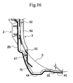
- the bottom plate 2E comprises legs 44 and a cover plate 45 as shown in Figs. 3 and 16.
- the legs 44 are members for supporting the container body 2.
- the legs 44 are constructed by proj ected bars formed along the overall width of two opposite sides of the bottom plate 2E.
- the cover plate 45 is a member for covering the lower side of the semiconductor wafers S housed in the container body 2.
- the cover plate 45 is provided so as to be curved downward between the legs 44.
- the cover plate 45 is set so that the gap "t" between the lower end of the semiconductor wafer S housed in the container body 2 and the cover plate 45 becomes a certain range, namely, the gap is set minimum so as to fully absorb the shock, for example, 3 mm for the following reason.
- the semiconductor wafer S can be supported with sufficient strength and a downward deviation can be suppressed.
- the height of the container body 2 is decreased and the size is reduced only by an amount corresponding to the reduction in the gap between the bottom plate 2E and the lower end of the semiconductor wafer S. Consequently, when the thin plate supporting container 1 is packed, the gap between the bottom of the thin plate supporting container 1 and a packing box is increased as compared with the conventional case, so that cushioning can be increased and the capability of absorbing a shock due a fall or the like can be largely improved.
- a lid unit receiving step 47 with which the lid unit 4 fits is provided in an upper end portion of the container body 2, as shown in Fig. 1, a lid unit receiving step 47 with which the lid unit 4 fits is provided.
- the lid unit receiving step 47 is formed by enlarging the upper end portion of the container body 2 to the dimensions of the lid unit 4.
- the lid unit 4 is attached to the lid unit receiving step 47 by fitting with the inner side of a perpendicular plate portion 47A of the lid unit receiving step 47 and coming into contact with a horizontal plate portion 47B. Further, a gasket 80 (refer to Fig. 29) attached to the under face of the lid unit 4 comes into contact with the horizontal plate portion 47B, thereby keeping air tightness in the thin plate supporting container 1.
- a fitting hole 48 is provided for fixing a special lid unit (not shown), used in the semiconductor fabricating process, to the container body 2 side.
- the fitting holes 48 are provided at four corners of the lid unit receiving step 47. The position and shape of the fitting hole 48 are properly set according to the special lid unit used in the semiconductor fabricating process.
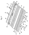
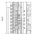
- the slotted plate 3 is, as shown in Fig. 1 and Figs. 16 to 23, a member for supporting the housed semiconductor wafers S from both sides.
- the slotted plate 3 is provided for each of the opposite side walls 2C and 2D in the container body 2.
- the slotted plate 3 is detachably attached to the inside of the container body 2.
- the slotted plate 3 is constructed mainly by a number of plate pieces 50 disposed in parallel at predetermined interval and supporting the wafers S one by one, and a supporting plate 51 for integrally supporting the plate pieces 50 in a state where the plate pieces 50 are disposed in parallel at predetermined intervals.
- the plate piece 50 is provided so as to extend from the inner side of the container body 2 to an outlet/inlet port (opening 2F) of the semiconductor wafers S.
- the plate piece 50 is formed so that a portion from the inner side to an intermediate position is curved along the periphery of the semiconductor wafer S and a portion from the intermediate position to the outlet/inlet port is along the container body 2 side.
- thin plate supporting projections 52 for supporting the semiconductor wafer S are provided on the inner side and the outlet/inlet port side in the plate piece 50.
- the thin plate supporting projection 52 on the outlet/inlet portion side is provided around an intersecting point of the inner periphery of the plate piece 50 and the periphery of the semiconductor wafer S.
- a V-shaped groove 53 is provided between the plate pieces 50 on the inner side.
- the semiconductor wafer S is fit into the V-shaped groove 53 and comes into contact with the bottom portion of the V-shaped groove 53.
- the semiconductor wafer S is supported in a center portion.
- Two handles 54 are provided on upper portion of the slotted plate 3.
- the handles 54 are portions grabbed by the user to lift the slotted plate 3.
- the slotted plate 3 is lifted by taking the two handles 54 between the user's fingers.
- the supporting plates 51 are provided in three positions, innermost side (lower left side in Fig. 17), an intermediate portion, and an inlet side (upper right side in Fig. 17) of each plate piece 50, and integrally support the plate pieces 50.
- the slotted plate 3 is detachably fixed to each of the side walls 2C and 2D which face each other in the container body 2 by an upper fitting portion 55 and a lower fitting portion 56.
- the upper fitting portion 55 is a member for supporting the upper portion of the slotted plate 3 to the container body 2.
- the upper fitting portion 55 is constructed by an upper fitting piece 57 and an upper receiving piece 58.
- the upper fitting piece 57 is provided for each of the side walls 2C and 2D which face each other in the container body 2.
- a step 59 is provided in an intermediate position in the vertical direction of each of the side walls 2C and 2D. In the step 59, the four upper fitting pieces 57 are provided. It is sufficient to provide two upper fitting pieces 57 at both ends. According to the size of the slotted plate 3 or the like, three or five or more upper fitting pieces 57 may be provided.
- the upper fitting piece 57 is formed in a U shape in plan view.
- the U-shaped upper fitting piece 57 includes a contact face 57A and a supporting face 57B.
- the contact face 57A is a part having a flat face shape which comes into contact with the slotted plate 3 side to perform positioning of the slotted plate 3 in the longitudinal direction (the direction from the left inner side to the right front side in Fig. 20) while preventing turn of the slotted plate 3. Since the slotted plate 3 is positioned in the longitudinal direction by using the contact face 57A as a reference, the contact face 57A is formed in accurate position and dimensions.
- the supporting face 57B is a part for maintaining a state where the contact face 57A is in contact with the slotted plate 3 side.
- the upper receiving piece 58 is a member which fits with the upper fitting piece 57 to perform positioning in the longitudinal direction of the slotted plate 3.
- the upper receiving piece 58 is provided in a position facing the upper fitting piece 57 in the slotted plate 3.
- the upper receiving piece 58 is constructed by a face 58 to be contacted and a face 58B to be supported.
- the face 58A to be contacted is a part with which the contact face 57A of the upper fitting piece 57 comes into contact to perform positioning of the slotted plate 3 in the longitudinal direction while suppressing turn of the slotted plate 3.
- the face 58A to be contacted is formed in a flat face shape and suppresses turn between the face 58A and the upper fitting piece 57.
- the face 58A to be contacted is formed at the tip of a projected bar 61 provided in a position corresponding to the contact face 57A of the fitting piece 57 in the slotted plate 3.
- the contact face 58A of the projected bar 61 comes into contact with the contact face 57A of the upper fitting piece 57, thereby positioning the slotted plate 3 in the longitudinal direction.
- two projected bars 61 come into contact with the contact face 57A of one upper fitting piece 57.
- the reason why the shape of the projected bar 61 is used is to prevent shrink at the time of molding and improve dimensional precision.
- the face 58B to be supported is a member which comes into contact with the supporting face 57B of the upper fitting piece 57 to thereby support the contacted face 58A in a state where the contacted face 58A is in contact with the contact face 57A of the upper fitting piece 57.
- the face 58B to be supported is formed on the rear face of a band-shaped plate member 63 supported on the slotted plate 3 side by a plurality of supporting plate pieces 62.
- the overall width of the plate member 63 serves as the face 58B to be supported.
- the supporting face 57B can come into contact with the plate member 63 in any position and can support the slotted plate 3.
- the contact faces 57A and 58A are in contact with each other while being supported by the supporting faces 57A and 57B, thereby preventing deformation such as deflection of the slotted plate 3 due to turn of the supporting portion of the slotted plate 3 and enabling accurate positioning in the longitudinal direction of the slotted plate 3 to be performed.
- the upper fitting portion 55 only positioning in the longitudinal direction of the slotted plate 3 is performed. Positioning in the other direction is carried out by the lower fitting portion 56.
- the lower fitting portion 56 is a member for supporting a lower portion of the slotted plate 3 to the container body 2 side.
- the lower fitting portion 56 has a vertical-direction positioning means 65 for performing positioning in the vertical direction of the slotted plate 3, a horizontal-direction positioning means 66 for performing positioning in the horizontal direction, and a front/rear direction positioning means 67 for performing positioning in the front/rear direction.
- the vertical-direction positioning means 65 is constructed by a vertical-direction supporting piece 68 and a lower plate 69.
- the vertical-direction supporting piece 68 is a member which is provided in the lower portion of each of the side walls 2C and 2D facing each other in the container body 2, fits in the lower portion of the slotted plate 3 and comes into contact with the lower end of the slotted plate 3, thereby positioning the slotted plate 3 in the vertical direction.
- the vertical-direction supporting piece 68 has a fitting notch 68A which fits with the slotted plate 3. The dimension in the vertical direction of the fitting notch 68A is accurately set to position the slotted plate 3 in the vertical direction.
- the lower plate 6 9 is a member for accurately positioning the slotted plate 3 in the vertical direction by fitting with the fitting notch 68A of the vertical-direction supporting piece 68.
- the lower plate 69 is a plate member extended downward from the lower portion of the slotted plate 3. Since the lower end face of the lower plate 69 is a part which fits with and in direct contact with the fitting notch 68A, the dimension in the vertical direction is accurately set.
- the horizontal-direction positioning means 66 is constructed by a notch 71 and a horizontal-direction supporting piece 72.
- the notch 71 is provided as a notch which opens downward in the lower plate 69 of the slotted plate 3.
- the horizontal-direction supporting piece 72 is a member which is provided between the vertical-direction supporting pieces 68 in each of the lower portions of the side walls 2C and 2D facing each other in the container body 2 and is fit in the notch 72 in the lower portion of the slotted plate 3, thereby positioning the slotted plate 3 in the horizontal direction.
- the horizontal-direction supporting piece 72 is formed in a wedge shape which is fit in the notch 71. By the fitting of the horizontal-direction supporting piece 72 to the notch 71, the slotted plate 3 is positioned accurately in the horizontal direction.
- the front/rear-direction positioning means 67 is constructed by a front/rear-direction supporting plate piece 73.
- the front/rear-direction supporting plate piece 73 is made of a band-shaped plate member.
- the front/rear-direction supporting plate piece 73 made of a band-shaped plate member is provided below the slotted plate 3 so as to extend horizontally to the back side of the slotted plate 3 and come into contact with the lower portion of each of the side walls 2C and 2D of the container body 2, thereby positioning the slotted plate 3 in the front/rear direction.
- a stopper 75 is provided in the lower portion of the slotted plate 3.
- the stopper 75 is a member for stopping disengagement to the up of the slotted plate 3.
- the stopper 75 is constructed by a locking piece 76 and a locking projection 77.
- the locking piece 76 is constructed by a band-shaped elastic plate piece 76A extended downward from the lower end of the slotted plate 3 and a locking pawl 76B provided on the locking projection 77 side of the elastic plate piece 76A.
- the locking projection 77 is a member to be locked by the locking pawl 76B of the locking piece 76.
- the locking pawl 76B of the locking piece 76 provided between the vertical-direction supporting pieces 68 of each of the side walls 2C and 2D fits with the locking projection 77, thereby preventing the slotted plate 3 from coming off to the above.
- the lid unit 4 is structured as shown in Fig. 2 and Figs. 27 to 30.
- the lid unit 4 is formed in a saucer shape which is open upward.
- the gasket 80 is provided between the lid unit 4 and the container body 2.
- the gasket 80 is constructed by a base end supporting portion 81 and a contact portion 82.
- the base end supporting portion 81 is a part which is fit in the fitting groove 4A on the lid unit 4 side to support the whole.
- the base end supporting portion 81 has an almost trapezoid shape in cross section.
- a seal piece 83 and an annular groove 84 are provided on the inside of the upper surface of the base end supporting portion 81.
- the seal piece 83 extends upward and comes into contact with the lid unit 4 side to keep air tightness.
- the annular groove 84 is provided on the outer side of the seal piece 83 and absorbs elastic deformation of the seal piece 83.
- the contact portion 82 is formed by being expanded from the base end supporting portion 81 into a flange shape.
- the contact portion 82 has a shape such that its intermediate portion is swollen upward (to the lid unit 4 side) and its outer periphery is folded downward (to the container body 2 side), in cross section.
- the portion 82A swollen upward in the contact portion 82 serves as a portion pressed by the lid unit 4, and the periphery is a portion which comes into contact with the container body 2 side. Accordingly, the intermediate portion to be pressed is pressed by the lid unit 4 in a state where the periphery is in contact with the container body 2 side, and the periphery is closely attached to the container body by elastic force of the contact portion 82.
- the latch mechanism 86 is a mechanism for fixing the lid unit 4 to the container body 2.
- the latch mechanism 86 is constructed by a first arm 87 and a second arm 88.
- the first arm 87 is a member for fixing the lid unit 4 to the container body 2 by directly being locked by a receiving portion (not shown) on the container body 2 side.
- the second arm 88 is a member which is swingably supported by the lid unit 4 and swingably supports the first arm 87.
- the first arm 87 has a locking pawl 90 and a grip 91.
- the locking pawl 90 is provided for the base end portion and comes into contact with the receiving portion on the container body 2 side to thereby fix the lid unit 4 to the container body 2 side.
- the grip 91 is a member for lifting the lid unit 4.
- the grip 91 is formed at the tip of the first arm 87, in a shape which is easily gripped by a hand.
- the first and second arms 87 and 88 are set in a position in a side of the lid unit 4 so that the grip 91 is easily gripped in a state where each of the first and second arms 87 and 88 swing to each limit.
- the locking pawl 90 of the base end of the first arm 87 does not come into contact with the container body 2.
- the first arm 87 is open up to 90° with respect to the second arm 88 and the second arm 88 is open up to 35° with respect to the container body 2.
- the first arm 87 is supported at 90° while its tip side is in contact in a state where the base end portion is pivoted by the L-shaped second arm 88.
- the second arm 88 is supported at 35° by a stopper 92.
- the thin plate pressing member 94 is a member for pressing and supporting the upper portion of the semiconductor wafer S housed in the container body 2 when the lid unit 4 is attached to the container body 2.
- the thin plate pressing member 94 is formed in an almost rectangular shape as shown in Figs. 24 to 26. Both ends in the longitudinal direction and the center portion of the thin plate pressing member 94 are fixed to the back face of the lid unit 4, and the portions between the both ends and the center portion serve as pressing portions 95.
- the pressing portion 95 is a member for elastically pressing and supporting the upper portion of the semiconductor wafer S and is constructed by a number of pressing bands 96 arranged in parallel.
- the pressing band 96 is an elastic member and is formed so as to be curved downward. Further, the pressing band 96 is formed in a wave shape in plan view (the shape in the state of Fig. 25) along the periphery of the semiconductor wafer S to prevent the semiconductor wafer S from entering the gap between the pressing bands 96.
- the shape of a side face of the pressing band 96 is an inverted mountain shape. In two apex positions of the mountain-shaped portion, fitting grooves 97 for supporting each semiconductor wafer S are provided at predetermined intervals. The fitting groove 97 is formed at an acute angle so as to sandwich the periphery of the semiconductor wafer S.
- the thin plate supporting container 1 constructed as described above is used as follows.
- the thin plate supporting container 1 is transported to a semiconductor fabricating factory or the like.
- the lid unit 4 is detached from the thin plate supporting container 1 carried in the semiconductor fabricating factory or the like, a special lid unit for the semiconductor fabricating factory or the like is attached to the thin plate supporting container 1 and the resultant is carried into a fabricating process.
- the upper portion of the slotted plate 3 attached in the container body 2 is supported by the upper fitting portion 55.
- the upper fitting piece 57 fits with the upper receiving piece 58 of the slotted plate 3. Accordingly, when the contact face 57A comes into contact with the face 58A to be contacted in a state where the supporting face 57B of the upper fitting piece 57 is in contact with the face 58B to be supported of the upper receiving piece 58, the upper portion of the slotted plate 3 is securely supported on the container body 2 side. Consequently, the slotted plate 3 does not swing and is securely supported in the supporting portion, and positioning in the front/rear direction of the slotted plate 3 is performed. In such a manner, deformation such as deflection of the slotted plate 3 is repressed and the slotted plate 3 is supported in an accurate position.
- the lower portion of the slotted plate 3 is supported by the lower fitting portion 56.
- the notch 71 on the slotted plate 3 side of the horizontal-direction positioning means 66 fits with the horizontal-direction supporting piece 72 on the container body 2 side, thereby positioning the slotted plate 3 in the horizontal direction.
- the locking piece 76 of the stopper 75 fits with the locking projection 77 to support the slotted plate 3 so as not to come off to the above.
- the slotted plate 3 can be thereby accurately positioned with the upper fitting portion 55 and the lower fitting portion 56 and easily fixed. In the case of detaching the slotted plate 3, the locking piece 76 is pulled to the front side to move the slotted plate 3 upward. It enables the slotted plate 3 to be easily detached.
- the plate piece 50 of the slotted plate 3 is formed so that a portion from the inner side to an intermediate position is curved along the periphery of the semiconductor wafer S and a portion from the intermediate position to the outlet/inlet port is formed along the container body 2 side.
- the semiconductor wafer S can be smoothly inserted/taken in/out the container body 2 and can be prevented from coming into contact with the plate piece 50.
- the thin plate supporting projection 52 for supporting the semiconductor wafer S is provided on each of the inner side and outlet/inlet side of the plate piece 50, and the thin plate supporting projection 52 on the outlet/inlet port side is provided around the intersection between the inner periphery of the plate piece 50 and the periphery of the semiconductor wafer S, so that the semiconductor wafer S inserted in the container body 2 can be stably supported.
- the upward swollen portion 82A of the contact portion 82 is pressed with the lid unit 4 in a state where the lid unit 4 is attached to the container body 2 so that the periphery of the gasket 80 of the lid unit 4 is closely attached to the container body 2 side. Consequently, even when the gasket 80 is deflected and a gap occurs between the gasket 80 and the container body 2, the peripheral portion can be closely attached to the container body 2 side with reliability. In such a manner, the container body 2 is sealed with the gasket 80.
- the seal piece 83 comes into contact with the lid unit 4 side and elastic deformation caused by the contact of the seal piece 83 is absorbed by the annular groove 84 to keep air tightness between the gasket 80 and the lid unit 4. Further, the upward swollen portion 82A of the contact portion 82 is also closely attached to the lid unit 4 to keep air tightness between the gasket 80 and the lid unit 4.
- the gap between the cover plate 45 for the container body 2 and the lower end of the semiconductor wafer S housed in the container body 2 is set minimum so as to fully absorb the shock, the size of the container body 2 is reduced.
- the size of the container body 2 is reduced, the size of the thin plate supporting container 1 itself is accordingly reduced. Consequently, when packed, the gap between the bottom of the thin plate supporting container 1 and a packing carton increases.
- the cushioning material in the larger gap can be also increased, and the shock absorbing capability in case of a shock of a fall or the like can be largely improved.
- the receiving rail 29B engages with the fitting rail 29A, the sliding portion 31 is fit in the supporting portion 30, and the top flange 5 or the like is slid to the inner side.
- the contact portion 36 of the inner-side locking pawl 34A is locked by the locking projection 33 and the contact portion 38 of the front-side locking pawl 34B is locked by the locking projection 33.
- the top flange 5 or the like can be easily attached.
- the supporting bar portion 39 of the front-side locking pawl 34B is lifted with the user's finger to come off the contact portion 38 from the locking projection 33, and the top flange 5 or the like is shifted to the front side. In such a manner, the top flange 5 or the like can be easily detached.
- the supporting portion 30 and the sliding portion 31 are set in such a manner that the interval is narrow on the front side and is wide on the inner side, so that the sliding portion 31 can easily fit with the supporting portion 30.
- top flange 5 or the like is supported by the fitting rails 29A and the receiving rails 29B, the top flange 5 can be smoothly moved and easily attached/detached.
- the contact portion 38 does not come off from the locking projection 33, and the supporting bar portion 39 supports the top flange 5 or the like with reliability to prevent the top flange 5 or the like from coming off.
- the user grips the grip 91 of the first arm 87 to lift the lid unit 4 up and covers the container body 2 with the lid unit 4 from above.
- the grip 91 is positioned on a side of the lid unit 4 in a state where the first and second arms 87 and 88 swing to each limit, and the grip 91 is in the position at which the user can easily lift the lid unit 4 in an optimum state.
- the grip 91 By gripping the grip 91, the user covers the container body 2 with the lid unit 4.
- the grip 91 is pushed downward.
- the locking pawl 90 in the base end portion of the first arm 87 comes into contact with the container body 2 side and the lid unit 4 is fixed to the container body 2.
- a user grips the grips 91 of the first arms 87 and pulls the grips 91 to the opposite sides.
- the locking pawl 90 in the base end portion of the first arm 87 is detached from the container body 2 side and the lid unit 4 is disengaged.
- the user still grips the grips 91 to lift the lid unit 4.
- the locking pawl 90 in the base end portion swings to a position in which it does not come into contact with the container body 2 in a state where the second arm 88 makes the first arm 87 swing to the limit. Consequently, even when the user lifts the lid unit 4 up, the locking pawl 90 does not come into contact with the container body 2, and the lid unit 4 can be easily detached.
- the grip 91 is supported in a position in which it is easily gripped on a side of the lid unit 4, and the locking pawl 90 is open to the position where it does not come into contact with the container body 2.
- the lid unit 4 can be easily attached/detached.
- the pressing band 96 is formed in a wave shape along the peripheries of the semiconductor wafers S, even if the semiconductor wafer S comes off from the fitting groove 97, the semiconductor wafer S does not enter the gap between the pressing bands 96.
- V-shaped groove plate piece 15 can be detachably attached to the supporting stand 16, it can be easily replaced in accordance with the material of the projection on the opposite side.
Landscapes
- Packaging Frangible Articles (AREA)
- Container, Conveyance, Adherence, Positioning, Of Wafer (AREA)
- Packaging Of Annular Or Rod-Shaped Articles, Wearing Apparel, Cassettes, Or The Like (AREA)
Priority Applications (1)
| Application Number | Priority Date | Filing Date | Title |
|---|---|---|---|
| EP10009630A EP2256783B1 (fr) | 2002-12-27 | 2003-12-23 | Conteneur de plaquettes fines |
Applications Claiming Priority (2)
| Application Number | Priority Date | Filing Date | Title |
|---|---|---|---|
| JP2002379340 | 2002-12-27 | ||
| JP2002379340A JP4146718B2 (ja) | 2002-12-27 | 2002-12-27 | 薄板支持容器 |
Related Child Applications (1)
| Application Number | Title | Priority Date | Filing Date |
|---|---|---|---|
| EP10009630.4 Division-Into | 2010-09-15 |
Publications (3)
| Publication Number | Publication Date |
|---|---|
| EP1434256A2 true EP1434256A2 (fr) | 2004-06-30 |
| EP1434256A3 EP1434256A3 (fr) | 2007-03-21 |
| EP1434256B1 EP1434256B1 (fr) | 2011-09-14 |
Family
ID=32463620
Family Applications (2)
| Application Number | Title | Priority Date | Filing Date |
|---|---|---|---|
| EP03029812A Expired - Lifetime EP1434256B1 (fr) | 2002-12-27 | 2003-12-23 | Conteneur de plaquettes fines |
| EP10009630A Expired - Lifetime EP2256783B1 (fr) | 2002-12-27 | 2003-12-23 | Conteneur de plaquettes fines |
Family Applications After (1)
| Application Number | Title | Priority Date | Filing Date |
|---|---|---|---|
| EP10009630A Expired - Lifetime EP2256783B1 (fr) | 2002-12-27 | 2003-12-23 | Conteneur de plaquettes fines |
Country Status (5)
| Country | Link |
|---|---|
| US (6) | US7383955B2 (fr) |
| EP (2) | EP1434256B1 (fr) |
| JP (1) | JP4146718B2 (fr) |
| KR (1) | KR100989781B1 (fr) |
| TW (1) | TWI239932B (fr) |
Cited By (9)
| Publication number | Priority date | Publication date | Assignee | Title |
|---|---|---|---|---|
| EP1734573A1 (fr) * | 2005-06-13 | 2006-12-20 | Miraial Co., Ltd. | Conteneur support de plaques minces Conteneur de plaquettes fines |
| EP1480254A3 (fr) * | 2003-05-19 | 2007-01-24 | Miraial Co., Ltd. | Dispositif de couvercle pour un récipient de plaques minces |
| EP1672686A3 (fr) * | 2004-12-15 | 2008-01-02 | Miraial Co., Ltd. | Récipient de stockage pour des tranches semi-conducteurs |
| US7455181B2 (en) | 2003-05-19 | 2008-11-25 | Miraial Co., Ltd. | Lid unit for thin plate supporting container |
| EP2544226A4 (fr) * | 2010-03-04 | 2017-03-29 | Shin-Etsu Polymer Co. Ltd. | Conteneur de stockage de substrats |
| CN108028216A (zh) * | 2015-08-25 | 2018-05-11 | 恩特格里斯公司 | 互锁模块化衬底支撑柱 |
| US20190189489A1 (en) * | 2016-08-19 | 2019-06-20 | Shin-Etsu Polymer Co., Ltd. | Substrate Storage Container |
| USD954769S1 (en) * | 2020-06-02 | 2022-06-14 | Applied Materials, Inc. | Enclosure system shelf |
| US12027397B2 (en) | 2020-03-23 | 2024-07-02 | Applied Materials, Inc | Enclosure system shelf including alignment features |
Families Citing this family (34)
| Publication number | Priority date | Publication date | Assignee | Title |
|---|---|---|---|---|
| TW581096U (en) * | 2003-03-05 | 2004-03-21 | Power Geode Technology Co Ltd | Wafer carrier and grip lever apparatus thereof |
| TWI276580B (en) * | 2003-12-18 | 2007-03-21 | Miraial Co Ltd | Lid unit for thin-plate supporting container |
| WO2005112107A1 (fr) * | 2004-05-17 | 2005-11-24 | Shin-Etsu Polymer Co., Ltd. | Récipient de stockage et procédé de positionnement de récipient |
| CN100521139C (zh) | 2005-05-06 | 2009-07-29 | 信越聚合物株式会社 | 基板收纳容器及其制造方法 |
| JP4809714B2 (ja) * | 2006-05-12 | 2011-11-09 | ミライアル株式会社 | 薄板収納容器 |
| SG172631A1 (en) * | 2006-05-29 | 2011-07-28 | Shinetsu Polymer Co | Substrate storage container |
| US20070295638A1 (en) * | 2006-06-21 | 2007-12-27 | Vantec Co., Ltd. | Wafer transportable container |
| JP4668133B2 (ja) * | 2006-06-28 | 2011-04-13 | 三甲株式会社 | ウエハ容器の位置決め構造 |
| US20080006559A1 (en) * | 2006-07-07 | 2008-01-10 | Entegris, Inc. | Substrate carrier and handle |
| US7581372B2 (en) * | 2006-08-17 | 2009-09-01 | Microtome Precision, Inc. | High cleanliness article transport system |
| US20080157455A1 (en) * | 2006-12-29 | 2008-07-03 | Applied Materials, Inc. | Compliant substrate holding assembly |
| JP4842879B2 (ja) * | 2007-04-16 | 2011-12-21 | 信越ポリマー株式会社 | 基板収納容器及びそのハンドル |
| KR101511813B1 (ko) * | 2007-11-09 | 2015-04-13 | 신에츠 폴리머 가부시키가이샤 | 리테이너 및 기판 수납 용기 |
| JP5084573B2 (ja) * | 2008-03-18 | 2012-11-28 | 信越ポリマー株式会社 | 基板収納容器 |
| JP4825241B2 (ja) * | 2008-06-17 | 2011-11-30 | 信越ポリマー株式会社 | 基板収納容器 |
| EP2306504B1 (fr) | 2008-06-23 | 2018-09-12 | Shin-Etsu Polymer Co. Ltd. | Corps de support et contenant de stockage de substrat |
| TWI363030B (en) * | 2009-07-10 | 2012-05-01 | Gudeng Prec Industral Co Ltd | Wafer container with top flange structure |
| US20140034548A1 (en) * | 2009-08-26 | 2014-02-06 | Texchem Advanced Products Incorporated Sdn Bhd | Wafer container |
| JP5363277B2 (ja) * | 2009-11-11 | 2013-12-11 | 信越ポリマー株式会社 | 基板収納容器、及び支持部材 |
| JP5281697B2 (ja) * | 2010-01-26 | 2013-09-04 | ミライアル株式会社 | 半導体ウエハ収納容器 |
| TWI515160B (zh) | 2010-10-19 | 2016-01-01 | 安堤格里斯公司 | 具自動凸緣之前開式晶圓容器 |
| WO2013069088A1 (fr) | 2011-11-08 | 2013-05-16 | ミライアル株式会社 | Récipient de stockage de tranches |
| CN103236410B (zh) * | 2013-04-28 | 2016-04-13 | 康可电子(无锡)有限公司 | 一种开有斜槽的石英舟结构 |
| KR102098790B1 (ko) * | 2013-06-19 | 2020-04-08 | 미라이얼 가부시키가이샤 | 기판수납용기 |
| KR102223033B1 (ko) | 2014-04-29 | 2021-03-04 | 삼성전자주식회사 | 웨이퍼 수납장치 |
| AU2015374114B2 (en) | 2014-12-29 | 2018-07-26 | Bioventus, Llc | Systems and methods for improved delivery of osteoinductive molecules in bone repair |
| TWI715623B (zh) * | 2015-08-31 | 2021-01-11 | 美商恩特葛瑞斯股份有限公司 | 具有壓縮閂鎖之前開基板容器 |
| JP7336923B2 (ja) * | 2019-09-05 | 2023-09-01 | 信越ポリマー株式会社 | 基板収納容器 |
| US12412764B2 (en) | 2020-03-31 | 2025-09-09 | Miraial Co., Ltd. | Substrate-accommodating container |
| TWI746045B (zh) * | 2020-07-07 | 2021-11-11 | 家登精密工業股份有限公司 | 基板載具鎖扣結構 |
| WO2023248464A1 (fr) * | 2022-06-24 | 2023-12-28 | ミライアル株式会社 | Boîtier de réception de substrat et dispositif de retenue arrière |
| TWI848670B (zh) * | 2022-06-30 | 2024-07-11 | 家登精密工業股份有限公司 | 保護包裝組件 |
| TWD232262S (zh) * | 2023-01-18 | 2024-07-11 | 日商信越聚合物股份有限公司 (日本) | 儲存及運送晶圓之容器 |
| CN116564867B (zh) * | 2023-05-05 | 2024-02-20 | 北京鑫跃微半导体技术有限公司 | 晶圆承载装置 |
Family Cites Families (43)
| Publication number | Priority date | Publication date | Assignee | Title |
|---|---|---|---|---|
| US985016A (en) * | 1910-03-19 | 1911-02-21 | William F Donnell | Milk-can. |
| US4520925A (en) * | 1983-08-09 | 1985-06-04 | Empak Inc. | Package |
| US4721207A (en) * | 1986-04-28 | 1988-01-26 | Tensho Electric Industrial Co., Ltd. | Hard disk container |
| US5123681A (en) * | 1991-03-20 | 1992-06-23 | Fluoroware, Inc. | Latch for wafer storage box for manual or robot operation |
| US5255797A (en) * | 1992-02-26 | 1993-10-26 | Fluoroware, Inc. | Wafer carrier with wafer retaining cushions |
| US5555981A (en) | 1992-05-26 | 1996-09-17 | Empak, Inc. | Wafer suspension box |
| KR100293906B1 (ko) * | 1992-11-17 | 2001-11-22 | 가끼자끼다께요시 | 수지제박판수납용기 |
| JPH0945759A (ja) | 1995-07-28 | 1997-02-14 | Mitsubishi Materials Shilicon Corp | パッケージ |
| JP3292800B2 (ja) | 1995-10-12 | 2002-06-17 | 信越ポリマー株式会社 | 密封容器のクランプ構造 |
| US5788082A (en) * | 1996-07-12 | 1998-08-04 | Fluoroware, Inc. | Wafer carrier |
| JPH10189704A (ja) | 1996-12-27 | 1998-07-21 | Komatsu Kasei Kk | 半導体ウェハ包装容器 |
| US6039186A (en) | 1997-04-16 | 2000-03-21 | Fluoroware, Inc. | Composite transport carrier |
| JP3249936B2 (ja) * | 1997-06-20 | 2002-01-28 | 住友金属工業株式会社 | 簡易着脱型蓋付き容器 |
| WO1998059229A2 (fr) | 1997-06-23 | 1998-12-30 | Genco Robert M | Moniteur pour conteneur destine a etre utilise en atmosphere regulee |
| JPH1126566A (ja) | 1997-06-30 | 1999-01-29 | Komatsu Ltd | 半導体ウェハ包装容器 |
| US6010008A (en) * | 1997-07-11 | 2000-01-04 | Fluoroware, Inc. | Transport module |
| JPH1174337A (ja) | 1997-08-28 | 1999-03-16 | Nippon Zeon Co Ltd | 熱可塑性樹脂製容器 |
| JP3838786B2 (ja) * | 1997-09-30 | 2006-10-25 | 信越ポリマー株式会社 | 精密基板収納容器及びその位置決め構造並びに精密基板収納容器の位置決め方法 |
| NL1010321C2 (nl) | 1997-10-20 | 1999-09-08 | Fluoroware Inc | Wafeldrager. |
| JP3938233B2 (ja) | 1997-11-28 | 2007-06-27 | 信越ポリマー株式会社 | 密封容器 |
| JPH11189288A (ja) | 1997-12-26 | 1999-07-13 | Mitsubishi Materials Corp | 板状部材収納容器 |
| US6474474B2 (en) * | 1998-02-06 | 2002-11-05 | Sumitomo Metal Industries, Ltd. | Sheet support container |
| EP1004524B1 (fr) | 1998-02-06 | 2014-12-31 | Sumco Corporation | Receptacle support de feuille |
| KR100510433B1 (ko) * | 1998-04-06 | 2006-07-27 | 다이니치쇼지 가부시키가이샤 | 컨테이너 |
| US6428729B1 (en) | 1998-05-28 | 2002-08-06 | Entegris, Inc. | Composite substrate carrier |
| DE19924182B4 (de) * | 1998-05-28 | 2008-04-17 | Entegris, Inc., Chaska | Träger für zu bearbeitende, aufzubewahrende und/oder zu transportierende Halbleiterwafer |
| US6216874B1 (en) * | 1998-07-10 | 2001-04-17 | Fluoroware, Inc. | Wafer carrier having a low tolerance build-up |
| JP2000043976A (ja) | 1998-07-27 | 2000-02-15 | Shin Etsu Polymer Co Ltd | 精密基板収納容器 |
| JP4208303B2 (ja) | 1998-09-08 | 2009-01-14 | 信越ポリマー株式会社 | 精密基板収納容器及びその組立方法 |
| US5992638A (en) | 1998-11-11 | 1999-11-30 | Empak, Inc. | Advanced wafer shipper |
| JP3998354B2 (ja) | 1998-11-24 | 2007-10-24 | 信越ポリマー株式会社 | 輸送容器及びその蓋体の開閉方法並びにその蓋体の開閉装置 |
| US6464081B2 (en) | 1999-01-06 | 2002-10-15 | Entegris, Inc. | Door guide for a wafer container |
| US6457750B1 (en) * | 1999-01-20 | 2002-10-01 | Southco, Inc. | Draw latch |
| JP2000289795A (ja) * | 1999-04-06 | 2000-10-17 | Kakizaki Mamufacuturing Co Ltd | 薄板収納・輸送容器 |
| JP3916342B2 (ja) * | 1999-04-20 | 2007-05-16 | 信越ポリマー株式会社 | 基板収納容器 |
| JP3556519B2 (ja) * | 1999-04-30 | 2004-08-18 | 信越ポリマー株式会社 | 基板収納容器の識別構造及び基板収納容器の識別方法 |
| JP2000323560A (ja) | 1999-05-11 | 2000-11-24 | Sekisui Chem Co Ltd | 気密容器 |
| TW437723U (en) * | 2000-06-16 | 2001-05-28 | Ind Tech Res Inst | Wafer box with foldable handle |
| WO2002047118A2 (fr) | 2000-12-04 | 2002-06-13 | Entegris, Inc. | Porte-plaquette avec plaque adaptatrice d'empilage |
| JP3942379B2 (ja) | 2001-05-22 | 2007-07-11 | 信越ポリマー株式会社 | 精密基板収納容器の位置決め部材 |
| JP3938293B2 (ja) | 2001-05-30 | 2007-06-27 | 信越ポリマー株式会社 | 精密基板収納容器及びその押さえ部材 |
| US20030188990A1 (en) * | 2001-11-14 | 2003-10-09 | Bhatt Sanjiv M. | Composite kinematic coupling |
| US6848578B2 (en) * | 2001-11-14 | 2005-02-01 | Entegris, Inc. | Wafer enclosure sealing arrangement for wafer containers |
-
2002
- 2002-12-27 JP JP2002379340A patent/JP4146718B2/ja not_active Expired - Lifetime
-
2003
- 2003-11-11 TW TW092131484A patent/TWI239932B/zh not_active IP Right Cessation
- 2003-12-02 US US10/725,288 patent/US7383955B2/en not_active Expired - Lifetime
- 2003-12-23 EP EP03029812A patent/EP1434256B1/fr not_active Expired - Lifetime
- 2003-12-23 EP EP10009630A patent/EP2256783B1/fr not_active Expired - Lifetime
- 2003-12-26 KR KR1020030097610A patent/KR100989781B1/ko not_active Expired - Lifetime
-
2006
- 2006-06-28 US US11/476,147 patent/US7497333B2/en not_active Expired - Lifetime
- 2006-06-28 US US11/476,075 patent/US7357257B2/en not_active Expired - Lifetime
- 2006-06-28 US US11/476,100 patent/US20060272973A1/en not_active Abandoned
- 2006-06-28 US US11/476,099 patent/US7520388B2/en not_active Expired - Lifetime
- 2006-06-28 US US11/476,148 patent/US7410061B2/en not_active Expired - Lifetime
Non-Patent Citations (1)
| Title |
|---|
| None |
Cited By (12)
| Publication number | Priority date | Publication date | Assignee | Title |
|---|---|---|---|---|
| EP1480254A3 (fr) * | 2003-05-19 | 2007-01-24 | Miraial Co., Ltd. | Dispositif de couvercle pour un récipient de plaques minces |
| US7455181B2 (en) | 2003-05-19 | 2008-11-25 | Miraial Co., Ltd. | Lid unit for thin plate supporting container |
| US7726490B2 (en) | 2003-05-19 | 2010-06-01 | Miraial Co., Ltd. | Lid unit thin plate supporting container |
| EP1672686A3 (fr) * | 2004-12-15 | 2008-01-02 | Miraial Co., Ltd. | Récipient de stockage pour des tranches semi-conducteurs |
| EP1734573A1 (fr) * | 2005-06-13 | 2006-12-20 | Miraial Co., Ltd. | Conteneur support de plaques minces Conteneur de plaquettes fines |
| EP2544226A4 (fr) * | 2010-03-04 | 2017-03-29 | Shin-Etsu Polymer Co. Ltd. | Conteneur de stockage de substrats |
| CN108028216A (zh) * | 2015-08-25 | 2018-05-11 | 恩特格里斯公司 | 互锁模块化衬底支撑柱 |
| CN108028216B (zh) * | 2015-08-25 | 2022-08-02 | 恩特格里斯公司 | 互锁模块化衬底支撑柱 |
| US20190189489A1 (en) * | 2016-08-19 | 2019-06-20 | Shin-Etsu Polymer Co., Ltd. | Substrate Storage Container |
| US10727099B2 (en) * | 2016-08-19 | 2020-07-28 | Shin-Etsu Polymer Co., Ltd. | Substrate storage container |
| US12027397B2 (en) | 2020-03-23 | 2024-07-02 | Applied Materials, Inc | Enclosure system shelf including alignment features |
| USD954769S1 (en) * | 2020-06-02 | 2022-06-14 | Applied Materials, Inc. | Enclosure system shelf |
Also Published As
| Publication number | Publication date |
|---|---|
| KR100989781B1 (ko) | 2010-10-25 |
| US7383955B2 (en) | 2008-06-10 |
| US7520388B2 (en) | 2009-04-21 |
| US20060272974A1 (en) | 2006-12-07 |
| EP1434256B1 (fr) | 2011-09-14 |
| US20060272972A1 (en) | 2006-12-07 |
| JP2004214269A (ja) | 2004-07-29 |
| US20060272966A1 (en) | 2006-12-07 |
| KR20040060805A (ko) | 2004-07-06 |
| TWI239932B (en) | 2005-09-21 |
| EP2256783A1 (fr) | 2010-12-01 |
| US20040124118A1 (en) | 2004-07-01 |
| EP2256783B1 (fr) | 2012-02-08 |
| US7357257B2 (en) | 2008-04-15 |
| US7410061B2 (en) | 2008-08-12 |
| US20060272975A1 (en) | 2006-12-07 |
| US20060272973A1 (en) | 2006-12-07 |
| JP4146718B2 (ja) | 2008-09-10 |
| TW200415087A (en) | 2004-08-16 |
| US7497333B2 (en) | 2009-03-03 |
| EP1434256A3 (fr) | 2007-03-21 |
Similar Documents
| Publication | Publication Date | Title |
|---|---|---|
| EP2256783B1 (fr) | Conteneur de plaquettes fines | |
| EP1993125B1 (fr) | Dispositif de couvercle pour un récipient de plaques minces | |
| JP3476052B2 (ja) | 輸送容器 | |
| TWM565877U (zh) | Wafer box | |
| CN103299412A (zh) | 具有自动凸缘的前部开口晶片容器 | |
| EP1411006A1 (fr) | Couvercle pour contenant de feuilles et contenant de feuilles | |
| JPH088332A (ja) | ウェーハ収納容器におけるウェーハバスケット | |
| JP4616319B2 (ja) | 薄板支持容器 | |
| JP4459015B2 (ja) | 基板収納容器 | |
| KR200384059Y1 (ko) | 포토마스크 보관케이스 | |
| JP3180693B2 (ja) | ウェーハ収納容器のウェーハ押え部材 | |
| CN112025651B (zh) | 运输安全箱 | |
| US20250385113A1 (en) | Wafer container housing and a wafer container transferring method | |
| JP2002299430A (ja) | 半導体材料搬送用保管容器 | |
| TWM676734U (zh) | 晶圓框架盒 | |
| JPH11163117A (ja) | 半導体ウェハ包装容器 | |
| JP4965380B2 (ja) | 処理治具用の収納ケース | |
| JPH09306982A (ja) | ウェーハ収納容器の係止構造 | |
| JP2004224409A (ja) | シート状品の収納ケース | |
| JP2003146390A (ja) | ロック錠を備えた搬送ボックス | |
| JPH10218186A (ja) | 積み重ね携帯容器 |
Legal Events
| Date | Code | Title | Description |
|---|---|---|---|
| PUAI | Public reference made under article 153(3) epc to a published international application that has entered the european phase |
Free format text: ORIGINAL CODE: 0009012 |
|
| AK | Designated contracting states |
Kind code of ref document: A2 Designated state(s): AT BE BG CH CY CZ DE DK EE ES FI FR GB GR HU IE IT LI LU MC NL PT RO SE SI SK TR |
|
| AX | Request for extension of the european patent |
Extension state: AL LT LV MK |
|
| PUAL | Search report despatched |
Free format text: ORIGINAL CODE: 0009013 |
|
| AK | Designated contracting states |
Kind code of ref document: A3 Designated state(s): AT BE BG CH CY CZ DE DK EE ES FI FR GB GR HU IE IT LI LU MC NL PT RO SE SI SK TR |
|
| AX | Request for extension of the european patent |
Extension state: AL LT LV MK |
|
| 17P | Request for examination filed |
Effective date: 20070716 |
|
| 17Q | First examination report despatched |
Effective date: 20070824 |
|
| AKX | Designation fees paid |
Designated state(s): DE |
|
| GRAP | Despatch of communication of intention to grant a patent |
Free format text: ORIGINAL CODE: EPIDOSNIGR1 |
|
| GRAS | Grant fee paid |
Free format text: ORIGINAL CODE: EPIDOSNIGR3 |
|
| GRAA | (expected) grant |
Free format text: ORIGINAL CODE: 0009210 |
|
| AK | Designated contracting states |
Kind code of ref document: B1 Designated state(s): DE |
|
| REG | Reference to a national code |
Ref country code: DE Ref legal event code: R096 Ref document number: 60338338 Country of ref document: DE Effective date: 20111103 |
|
| PLBE | No opposition filed within time limit |
Free format text: ORIGINAL CODE: 0009261 |
|
| STAA | Information on the status of an ep patent application or granted ep patent |
Free format text: STATUS: NO OPPOSITION FILED WITHIN TIME LIMIT |
|
| 26N | No opposition filed |
Effective date: 20120615 |
|
| REG | Reference to a national code |
Ref country code: DE Ref legal event code: R097 Ref document number: 60338338 Country of ref document: DE Effective date: 20120615 |
|
| PGFP | Annual fee paid to national office [announced via postgrant information from national office to epo] |
Ref country code: DE Payment date: 20221020 Year of fee payment: 20 |
|
| REG | Reference to a national code |
Ref country code: DE Ref legal event code: R071 Ref document number: 60338338 Country of ref document: DE |