EP1437150B2 - Seringue prealablement remplie comportant deux chambres - Google Patents
Seringue prealablement remplie comportant deux chambres Download PDFInfo
- Publication number
- EP1437150B2 EP1437150B2 EP02762777.7A EP02762777A EP1437150B2 EP 1437150 B2 EP1437150 B2 EP 1437150B2 EP 02762777 A EP02762777 A EP 02762777A EP 1437150 B2 EP1437150 B2 EP 1437150B2
- Authority
- EP
- European Patent Office
- Prior art keywords
- bypass
- plug member
- end portion
- cylindrical member
- chamber
- Prior art date
- Legal status (The legal status is an assumption and is not a legal conclusion. Google has not performed a legal analysis and makes no representation as to the accuracy of the status listed.)
- Expired - Lifetime
Links
Images


Classifications
-
- A—HUMAN NECESSITIES
- A61—MEDICAL OR VETERINARY SCIENCE; HYGIENE
- A61M—DEVICES FOR INTRODUCING MEDIA INTO, OR ONTO, THE BODY; DEVICES FOR TRANSDUCING BODY MEDIA OR FOR TAKING MEDIA FROM THE BODY; DEVICES FOR PRODUCING OR ENDING SLEEP OR STUPOR
- A61M5/00—Devices for bringing media into the body in a subcutaneous, intra-vascular or intramuscular way; Accessories therefor, e.g. filling or cleaning devices, arm-rests
- A61M5/178—Syringes
- A61M5/28—Syringe ampoules or carpules, i.e. ampoules or carpules provided with a needle
- A61M5/284—Syringe ampoules or carpules, i.e. ampoules or carpules provided with a needle comprising means for injection of two or more media, e.g. by mixing
-
- A—HUMAN NECESSITIES
- A61—MEDICAL OR VETERINARY SCIENCE; HYGIENE
- A61M—DEVICES FOR INTRODUCING MEDIA INTO, OR ONTO, THE BODY; DEVICES FOR TRANSDUCING BODY MEDIA OR FOR TAKING MEDIA FROM THE BODY; DEVICES FOR PRODUCING OR ENDING SLEEP OR STUPOR
- A61M5/00—Devices for bringing media into the body in a subcutaneous, intra-vascular or intramuscular way; Accessories therefor, e.g. filling or cleaning devices, arm-rests
- A61M5/178—Syringes
- A61M5/31—Details
- A61M5/3129—Syringe barrels
- A61M2005/3132—Syringe barrels having flow passages for injection agents at the distal end of the barrel to bypass a sealing stopper after its displacement to this end due to internal pressure increase
-
- A—HUMAN NECESSITIES
- A61—MEDICAL OR VETERINARY SCIENCE; HYGIENE
- A61M—DEVICES FOR INTRODUCING MEDIA INTO, OR ONTO, THE BODY; DEVICES FOR TRANSDUCING BODY MEDIA OR FOR TAKING MEDIA FROM THE BODY; DEVICES FOR PRODUCING OR ENDING SLEEP OR STUPOR
- A61M5/00—Devices for bringing media into the body in a subcutaneous, intra-vascular or intramuscular way; Accessories therefor, e.g. filling or cleaning devices, arm-rests
- A61M5/178—Syringes
- A61M5/31—Details
- A61M5/3129—Syringe barrels
Definitions
- the present invention relates to a dual-chamber type prefilled syringe comprising a cylindrical member which has a base end portion formed with an insertion inlet for a plunger rod and a frontend portion provided with an injection needle attaching portion, an end plug member being inserted and fitted into a side of the base end portion, a middle plugmember being arranged between the front end portion and the end plug member, the cylindrical member having an interior area hermetically partitioned into a front chamber on a side of the front end portion and a rear chamber on the side of the base end portion, the cylindrical member having an inner surface between the front end portion and the middle plug member, projected outwards to form a bypass in the shape of a groove, the bypass having a length in a direction of an axis of the cylindrical member, which is made longer than the middle plug member.
- a middle plug member 64 is arranged between both of the plug members 62 and 63 to hermetically partition an interior area of the cylindrical member 52 into a front chamber 65 on the side of the front end portion 53 and a rear chamber 66 on the side of the base end portion 54.
- An injection needle 58 is attached to the injection needle attaching portion 56 and is covered with a protector cap 59.
- the cylindrical member 52 has an inner surface between the front plug member 62 and the middle plug member 64, formed with a bypass 70 projecting outwards and shaped like a groove.
- This bypass 70 has a length in a direction of an axis 69 of the cylindrical member, which is longer than the middle plug member 64.
- the front chamber 65 contains, e.g., powdered medicine 67 and the rear chamber 66 accommodates dissolving solution or the like liquid agent 68, respectively and hermetically.
- the middle plug member 64 advances with an inner pressure of the liquid agent 68 hermetically enclosed in the rear chamber 66.
- the front plug member 62 also advances during an initial term of the forward pushing of the plunger rod 57.
- the injection needle attaching portion 56 has an interior area formed with a plug member accommodating portion 60, which has an inner peripheral wall concaved to provide communication grooves 61.
- the front chamber 65 communicates with the injection needle 58 via the communication grooves 61 and a clearance between the front plug member 62 and an inner surface of the plug member accommodating portion 60.
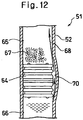
- the liquid agent 68 which passes through the bypass 70 owns so large a kinetic energy that for example, as shown in Fig. 12 , this liquid agent 68 passes through and splashes out of the bypass 70 as if it were a water pistol.
- the liquid agent 68 splashes too vigorously, there is a likelihood that it reaches the front end portion 53 and collides against a rear surface of the front plug member 62 within the plug member accommodating chamber 60 to flow into the communication grooves 61 and the clearance between the front plug member 62 and the inner surface of the plug member accommodating portion 60.
- the plunger rod 57 is pushed forward acceleratedly in order to carry out this communicating operation quickly, the liquid agent 68 splashes out more vigorously to flow into the grooves 61 and the clearance more easily.
- the water pistol phenomenon has also occurred in the dual-chamber type prefilled syringe which does not use the front plug member. Accordingly, there was a likelihood that the liquid agent which splashed out of the bypass flowed into a communication passage between the bypass and the injection needle to have leaked out of the injection needle.
- the present invention seeks to reduce the so-called water pistol phenomenon in which the dissolving solution or the like liquid agent splashes out of the bypass when communicating the front chamber with the rear chamber to prevent the liquid agent from leaking out of the front end of the injection needle.
- the dual-chamber-type prefilled syringe in accordance with the invention is characterised in that the bypass has an inner surface an end surface of which is situated on aside of an inlet formed on the side of the base end portion and uprises outwards by an angle which is made larger than 45 degrees with respect to the axis of the cylindrical member.
- Figs. 1 to 10 show embodiments of the present invention.
- a first embodiment fits and inserts an end plug member 13 into a side of a base end portion 4 formed with an insertion inlet 5 for a plunger rod 7, of a cylindrical member 2.
- a middle plug member 14 is arranged between the end plug member 13 and a front end portion 3 provided with an injection needle attaching portion 6.
- the cylindrical member 2 has an interior area hermetically partitioned into a front chamber 15 on a side of the front end portion 3 and a rear chamber 16 on the side of the base end portion 4.
- the cylindrical member 2 has an inner surface between the front end portion 3 and the middle plug member 14, provided with a bypass 20 which projects outwards and is shaped like a groove.
- This bypass 20 has a length in a direction of an axis 19 of the cylindrical member 2, which is longer than the middle plug member 14.
- the bypass 20 has an inner surface an end surface of which is positioned on a side of an inlet 21 formed on the side of the base end portion 4.
- the end surface uprises outwards by an angle ( ⁇ ) which is larger
- the present invention offers the following advantages.
- the bypass Since the bypass has the end surface on the inlet side made to uprise at an angle larger than 45 degrees, the liquid agent which flows from the rear chamber into this bypass is directed largely outwards and collides against a groove bottom surface of the bypass to have part of its kinetic energy absorbed. As a result, it is possible to reduce the so-called water pistol phenomenon in which the dissolving solution or the like liquid agent splashes out of the bypass and to prevent the liquid agent which has splashed out of the bypass from reaching the front end portion of the cylindrical member. And eventually it is possible to inhibit the liquid agent from leaking out of the front end of the injection needle when communicating the front chamber with the rear chamber.
- a second embodiment inserts and fits the end plug member 13 into the side of the base end portion 4 formed with the insertion inlet 5 of the plunger rod 7.
- the middle plug member 14 is arranged between the end plug member 13 and the front end portion 3 provided with the injection needle attaching portion 6.
- the cylindrical member 2 has the interior area hermetically partitioned into the front chamber 15 on the side of the front end portion 3 and the rear chamber 16 on the side of the base end portion 4.
- the cylindrical member 2 has the inner surface between the front end portion 3 and the middle plug member 14, formed with the bypass 20 which projects outwards and is shaped like a groove.
- the bypass 20 has a length in the direction of the axis 19 of the cylindrical member 2, which is longer than the middle plug member 14.
- the bypass 20 has a longitudinal direction inclined with respect to the axis 19 of the cylindrical member 2. Further, the bypass has the longitudinal direction inclined with respect to the axis of the cylindrical member by an angle which is preferably set to at least 10 degrees, more preferably at least 20 degrees, and much more preferably at least 25 degrees.
- the liquid agent which flows from the rear chamber into the bypass collides against a lateral surface on the side of the front end portion of the bypass inner surface and further the liquid agent which flows from the bypass into the front chamber circulates along the inner surface of the cylindrical member to have part of its kinetic energy absorbed.
- the liquid agent which has flowed out of the bypass obliquely circulates spirally, so that a distance along a direction in which the liquid agent circulates until it reaches the front end portion of the cylindrical member becomes greater than a distance of the axial direction of the cylindrical member. This results in preventing the liquid agent from arriving at the front end portion, thereby more effectively inhibiting the leakage of the liquid agent from the front end of the injection needle.
- a third embodiment fits and inserts the end plug member 13 into the side of the base end portion 4 formed with the insertion inlet 5 for the plunger rod 7.
- the middle plug member 14 is arranged between the end plug member 13 and the front end portion 3 provided with the injection needle attaching portion 6.
- the cylindrical member 2 has the interior area hermetically partitioned into the front chamber 15 on the side of the front end portion 3 and the rear chamber 16 on the side of the base end portion 4.
- the cylindrical member 2 has the inner surface between the front end portion 3 and the middle plug member 14, formed with the bypass 20 projecting outwards and shaped like a groove.
- This bypass 20 has a length in the direction of the axis 19 of the cylindrical member 2, which is longer than the middle plug member 14.
- the bypass 20 has a mid portion provided with a bent portion 23.
- the bent portion 23 may be provided at a portion of the bypass, for example, in the shape of an angled 'C' or at a plurality of portions thereof.
- the bypass Since the bypass has the mid portion provided with the bent portion, the liquid agent which flows from the rear chamber into the bypass collides against the inner surface of the bypass at the bent portion when it passes through the bypass to result in having its part of kinetic energy absorbed.
- the so-called water pistol phenomenon in which the dissolving solution or the like liquid agent splashes out of the bypass and to prevent the liquid agent which has splashed out of the bypass from reaching the front end portion of the cylindrical member, which can in turn inhibit the leakage of the liquid agent from the front end of the injection needle when communicating the front chamber with the rear chamber.
- the first bypass 20a has a length in a direction of the axis 19 of the cylindrical member 2, which is shorter than the middle plug member 14.
- a length in the direction of the axis 19 of the cylindrical member 2 from an inlet 21a of the first bypass 20a to an outlet 22b of the second bypass 20b is longer than the middle plug member 14.
- the middle plug member 14 has an outer peripheral surface concaved to form a groove 24 which communicates the first bypass 20a and the second bypass 20b with each other when the middle plug member 14 has moved to a position where the bypasses 20 are formed.
- the rear chamber communicates with the front chamber via the first bypass, the concaved groove and the second bypass in the mentioned order.
- the liquid agent which has flowed from the rear chamber into the first bypass collides against the end surface on the outlet side of the first bypass to flow into the concaved groove and collide against an inner surface of the same. Further, it flows into the second bypass to collide against an inner surface of the second bypass and then flow into the front chamber.
- the liquid agent collides against the end surface on the outlet side of the first bypass, the inner surface of the concaved groove and the inner surface of the second bypass, it has part of its kinetic energy absorbed.
- the bypass 20 has the inner surface the end surface of which is situated on the side of the inlet 21 formed on the side of the base end portion 4 and uprises outwards by an angle ( ⁇ ) which can be formed larger than 45 degrees with respect to the axis 19 of the cylindrical member 2 as well as in the first invention.
- the bypass 20 has the inner surface an end surface of which is situated on a side of an outlet 22 formed on the side of the front end portion 3 and uprises outwards by an angle ( ⁇ ') which can be formed larger than 45 degrees with respect to the axis 19 of the cylindrical member 2.
- ⁇ ' an angle which can be formed larger than 45 degrees with respect to the axis 19 of the cylindrical member 2.
- the inlet side end surface or the outlet side end surface of the bypass uprises at an angle preferably set to at least 50 degrees, more preferably to at least 60 degrees.
- the uprising angle means an average angle at the mid portion of the end surface. Accordingly, needless to say, the end surface may be connected to the inner surface of the cylindrical member or to the groove bottom portion of the bypass, by a portion which consists of a smooth curve.
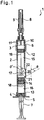
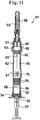
- Figs. 1 to 3 show a first embodiment.
- Fig. 1 is a sectional view of a dual-chamber type prefilled syringe.
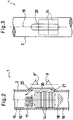
- Fig. 2 illustrates, in an enlarged section, the neighborhood of a bypass when conducing a communicating operation.
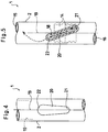
- Fig. 3 is a front view of the bypass portion.
- this dual-chamber type prefilled syringe 1 comprises a cylindrical member 2 made of glass or plastics, which is provided at its front end portion 3 with an injection needle attaching portion 6 and at its base end portion 4 with an insertion inlet 5 for a plunger rod 7.
- the injection needle attaching portion 6 has a front end to which an injection needle 8 is attached. A protector cap 9 is covered around the injection needle 8. Further, the injection needle attaching portion 6 has an interior area formed with a plug member accommodating portion 10 which has an inner peripheral wall concaved to provide communication grooves 11.
- the cylindrical member 2 has the front end portion 3 into a side of which a front plug member 12 is inserted and fitted and has a base end portion into a side of which an end plug member 13 is inserted and fitted.
- a middle plug member 14 is arranged between the both plug members 12 and 13.
- the cylindrical member 2 has an interior area hermetically partitioned into a front chamber 15 on the side of the front end portion 3 and a rear chamber 16 on the side of the base end portion 4.
- the front chamber 15 accommodates, for example, powdered medicine 17 and the rear chamber 16 contains dissolving solution or the like liquid agent 18, respectively and hermetically.
- the front chamber accommodates the powdered medicine and the rear chamber contains dissolving solution or the like liquid agent
- this prefilled syringe may contain liquid medicine in the front chamber and a second liquid medicine in the rear chamber.
- the middle plug member 14 is composed of a plug member on the side of the powdered medicine and another plug member on the side of the liquid agent.
- the middle plug member may be composed of a single plug member.
- the cylindrical member 2 has an inner surface between the front plug member 12 and the middle plug member 14, projected outwards to form a bypass 20 in the shape of a groove.
- This bypass 20 has a length in a direction of an axis 19 of the cylindrical member 2, which is longer than the middle plug member 14.
- the bypass 20 has an inner surface an end surface of which is situated on a side of an inlet 21 formed on the side of the base end portion 4 and uprises outwards by an angle ( ⁇ ) which is formed larger than 45 degrees, for example, about 60 degrees with respect to the axis 19 of the cylindrical member 2.
- an end surface on a side of an outlet 22 formed on the side of the front end portion 3 of the bypass 20 uprises outwards by an angle ( ⁇ ') which is also set to about 60 degrees with respect to the axis 19 of the cylindrical member 2.
- the respective uprising angles ( ⁇ and ⁇ ') the larger the better. But when taking into consideration the readiness of forming the bypass 20 and the smoothness of an outer surface of the cylindrical member 2, they are generally formed within a range of 50 degrees to 70 degrees.
- An outer appearance of the bypass 20, as shown in Fig. 3 is formed so as to have substantially a constant width along the axis 19 of the cylindrical member 2.
- the bypass 20 of the present invention is not limited to the shape of the present embodiment.
- a groove width may be formed larger on the side of the outlet 22 than on the side of the inlet 21.
- the largest groove width on the side of the outlet 22 may be formed 1.2 times to 5 times a width on the side of the inlet 21.
- the liquid agent flows from the bypass 20 into the front chamber 15 at a reduced speed, which is more preferable.
- the plunger rod 7 has its front end engaged in screw-thread relationship with the end plug member 13 and is pushed forward, thereby advancing the end plug member 13 to advance the middle plug member 14 with an inner pressure of the liquid agent 18 hermetically contained in the rear chamber 16. Further, with a pressure in the front chamber 15 increased, the front plug member 12 also advances. When this front plug member 12 advances and enters into the plug member accommodating portion 10, the front chamber 15 communicates with the injection needle 8 via the communication grooves 11 and a clearance between the front plug member 12 and an inner surface of the plug member accommodating portion 10.
- the rear chamber 16 communicates with the front chamber 15 through the bypass 20, so that the liquid agent 18 within the rear chamber 16 tries to flow into the front chamber vigorously via the bypass 20 if the plunger rod 7 is pushed forward.
- the liquid agent 18 which flows from the rear chamber 16 into the bypass 20 is oriented outwards largely because the end surface on the side of the inlet 21 of the bypass 20 uprises at an angle ( ⁇ ) formed to about 60 degrees, and it collides against the groove bottom surface of the bypass 20 to have part of its kinetic energy absorbed. Further, this liquid agent 18 passes through the bypass 20 straightly. However, the end surface on the side of the outlet 22 also uprises at an angle ( ⁇ ') formed to about 60 degrees, so that it collides against this end surface as well to have also part of its kinetic energy absorbed at this time.
- the end surface on the side of the inlet 21 uprises at a large angle ( ⁇ ) to result in quickly enlarging the clearance between the middle plug member 14 and the inner surface of the bypass 20 through even a slight advancement of the middle plug member 14, the liquid agent 18 flows from the rear chamber 16 into the bypass 20 at a abruptly reduced speed. As a result, the liquid agent 18 moderately flows and enters from the bypass 20 into the front chamber 15.
- the middle plug member 14 On further pushing the plunger rod 7 forward to advance the end plug member 13, the middle plug member 14 has a front end advanced ahead of the outlet 22 of the bypass 20 to clog the bypass 20. This terminates the communicating operation. In this state, if the dual-chamber type prefilled syringe 1 is shook or the like, the powdered medicine 17 is suspended or dissolved in the liquid agent 18 to complete the preparation for administering the medicine.
- Fig. 5 shows a second embodiment of the present invention and is a partly broken front view of the neighborhood of the bypass of the dual-chamber type prefilled syringe.
- the cylindrical member 2 is formed with the bypass 20 in the shape of a groove, which projects outwards and has its longitudinal direction inclined by an angle of about 20 degrees with respect to the axis 19 of the cylindrical member 2.
- the bypass 20 has a length in the direction of the axis 19 of the cylindrical member 2, which is made longer than the middle plug member 14.
- the middle plug member 14 reaches the position where the bypass 20 is formed, on conducting the communicating operation.
- the middle plug member 14 has its rear end advanced ahead of the inlet 21 of the bypass 20, the rear chamber 16 communicates with the front chamber 15 through the bypass 20.
- the liquid agent 18 within the rear chamber 16 flows into the front chamber 15 via the bypass 20.
- the bypass 20 has its longitudinal direction inclined with respect to the axis 19 of the cylindrical member 2, the liquid agent 18 which flows into the bypass 20 collides against a lateral surface which is situated on the side of the front end portion, of the inner surface of the bypass 20 to have part of its kinetic energy absorbed.
- the liquid agent 18 which flows from the bypass 20 into the front chamber 15 is circulated along the inner surface of the cylindrical member 2, thereby having part of its kinetic energy absorbed as well.
- the liquid agent 18 which flows out of the bypass 20 circulates spirally, so that it reaches the front plug member at the front end portion 3 by a distance which is longer than that by which it goes straight along the direction of the axis 19 of the cylindrical member 2. As a result, it is possible to prevent the liquid agent 18 which flows out of the bypass 20 from arriving at the front end portion
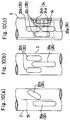
- Fig. 6 shows a third embodiment of the present invention and is a partly broken front view of the neighborhood of the bypass of the dual-chamber type prefilled syringe.
- the cylindrical member 2 is formed with the bypass 20 in the shape of the groove, which is provided at its mid portion with a bent portion 23 formed in the shape of an angled 'C'.
- the bypass 20 has a length in the direction of the axis 19 of the cylindrical member, which is longer than the middle plug member 14.
- the middle plug member 14 reaches the position where the bypass 20 is formed, on conducting the communicating operation.
- the middle plug member 14 has its rear end advanced ahead of the inlet 21 of the bypass 20, the rear chamber 16 communicates with the front chamber 15 through this bypass 20.
- the liquid agent 18 within the rear chamber 16 flows into the front chamber 15 via the bypass 20.
- the liquid agent 18 collides against the inner surface of the bypass 20 at the bent portion 23 to have part of its kinetic energy absorbed.
- the bypass 20 is inclined with respect to the axis 19 of the cylindrical member on the side of the outlet 22 and the liquid agent 18 which flows from the bypass 20 into the front chamber 15 is circulated along the inner surface of the cylindrical member 2 as well as in the second embodiment, thereby having part of its kinetic energy absorbed.
- the liquid agent 18 which has flowed into the front chamber 15 circulates along the inner surface of the cylindrical member 2, it reaches the front plug member at the front end portion by a distance longer than that by which it goes straight along the direction of the axis 19 of the cylindrical member 2 as in the second embodiment. From this point of view, it is possible to prevent the liquid agent 18 which flows out of the bypass 20 from arriving at the front end portion of the cylindrical member.
- the bypass is formed in the shape of the angled 'C'.
- the above-mentioned bent portion may be provided at optional one or more than one positions at the mid portion of the bypass like the respective modifications as shown in Fig. 7 .
- the first modification shown in Fig. 7(a) is the same as the third embodiment in that the bent portion 23 is provided at one position of the mid portion of the bypass 20.
- the bypass 20 has a portion extending from this bent portion 23 toward the side of the inlet 21, formed along the axis 19 of the cylindrical member 2 and has another portion which extends from the bent portion 23 toward the side of the outlet 22, inclined with respect to the axis 19 of the cylindrical member 2.
- each of the second to fourth modifications shown in Figs. 7(b) to 7(d) is formed with bent portions (23, 23) at two positions of the bypass 20.
- Fig. 8 shows a fourth embodiment and is a sectional view of the neighborhood of the bypass of the dual-chamber type prefilled syringe.
- the cylindrical member 2 is formed with two bypasses 20 which consist of a first bypass 20a on the side of the base end portion and a second bypass 20b on the side of the font end portion.
- the first bypass 20a has a length in the direction of the axis 19 of the cylindrical member 2, which is shorter than the middle plug member 14.
- a length in the direction of the axis 19 of the cylindrical member 2 which extends from the inlet 21a of the first bypass 20a to the outlet 22b of the second bypass 20b is formed longer than the middle plug member 14.
- the middle plug member 14 has a peripheral surface concaved to form a groove 24.
- the middle plug member 14 has moved to the position where the bypasses 20 are formed, the first bypass 20a has the outlet 22a communicated with the inlet 21b of the second bypass 20b through the groove 24.
- the rear chamber 16 communicates with the front chamber 15 via the first bypass 20a, the concaved groove 24 and the second bypass 20b in the mentioned order.
- the liquid agent 18 within the rear chamber 16 flows into the first bypass 20a.
- the liquid agent 18 collides against the outlet 22a of the first bypass 20a and flows into the groove 24.
- the second bypass 20b after it has collided against an inner surface of the groove 24, it also collides against an inner surface of the second bypass 20b and thereafter flows into the front chamber 15.
- the liquid agent 18 has part of its kinetic energy absorbed when it collides against the outlet 22a of the first bypass 20a, the inner surface of the concaved groove 24 and the inner surface of the second bypass 20b to result in flowing moderately and entering the front chamber 15.
- the first bypass 20a is arranged side by side with the second bypass 20b in the direction of the axis 19 of the cylindrical member 2.
- the first bypass 20a may be arranged at a position peripherally different from another position where the second bypass 20b is formed.
- the first bypass 20a is arranged opposite to the second bypass 20b in a peripheral direction of the cylindrical member 2. If they are constructed as such, the inlet 21b of the second bypass 20b can be arranged behind the outlet 22a of the first bypass 20a. Accordingly, the groove 24 formed by concaving the middle plug member 14 can be made to have a narrow width.
- bypass can be modified as shown in Fig. 10 .
- the second bypass 20b has its longitudinal direction inclined with respect to the axis 19 of the cylindrical member 2.
- a plurality of second bypasses 20b, 20b are formed on the opposite sides of the first bypass 20a.
- a plurality of third bypasses 20c, 20c are formed over the opposite sides of the first bypass 20a and the second bypass 20b.
- the groove 24 formed by concaving the outer peripheral surface of the middle plug member 14 consists of a first concaved groove 24a which communicates the first bypass 20a with one third bypass 20c and a second concaved groove 24b which communicates the other third bypass 20c with the second bypass 20b.
Landscapes
- Health & Medical Sciences (AREA)
- Vascular Medicine (AREA)
- Engineering & Computer Science (AREA)
- Anesthesiology (AREA)
- Biomedical Technology (AREA)
- Heart & Thoracic Surgery (AREA)
- Hematology (AREA)
- Life Sciences & Earth Sciences (AREA)
- Animal Behavior & Ethology (AREA)
- General Health & Medical Sciences (AREA)
- Public Health (AREA)
- Veterinary Medicine (AREA)
- Infusion, Injection, And Reservoir Apparatuses (AREA)
Claims (5)
- Seringue préremplie du type à chambre double comprenant un élément cylindrique (2) qui comporte une partie d'extrémité de base (4) formée avec une entrée d'insertion (5) pour une tige piston (7) et une partie d'extrémité frontale (3) dotée d'une partie de fixation d'aiguille d'injection (6), un élément de bouchon d'extrémité (13) étant inséré et monté dans un côté de la partie d'extrémité de base (4), un élément de bouchon intermédiaire (14) étant agencé entre la partie d'extrémité frontale (3) et l'élément de bouchon d'extrémité (13), l'élément cylindrique (2) ayant une zone intérieure hermétiquement compartimentée en une chambre frontale (15) sur un côté de la partie d'extrémité frontale (3) et une chambre arrière (16) sur le coté de la partie d'extrémité de base (4), l'élément cylindrique (2) ayant une surface interne et une surface externe entre la partie d'extrémité frontale (3) et l'élément de bouchon intermédiaire (14), la surface interne et la surface externe étant projetées vers l'extérieur pour former une dérivation (20) sous forme de rainure, la dérivation (20) ayant une longueur dans un sens d'un axe (19) de l'élément cylindrique (2), laquelle est rendue plus longue que l'élément de bouchon intermédiaire (14), la seringue étant caractérisée en ce que
la dérivation (20) a une surface interne dont une surface d'extrémité est située sur un côté d'une entrée (21) formée sur le côté de la partie d'extrémité de base (4) et s'élève vers l'extérieur par un angle (θ) qui est rendu plus grand que 15 degrés par rapport à l'axe (19) de l'élément cylindrique (2). - Seringue selon la revendication 1, dans laquelle la dérivation (20) a un sens longitudinal incliné par rapport à l'axe (19) de l'élément cylindrique (2).
- Seringue selon la revendication 1, dans laquelle la dérivation (20) a une partie centrale dotée d'une partie courbe (23).
- Seringue selon la revendication 1, comprenant une pluralité de dérivations dont une première dérivation (20a) sur le côté de la partie d'extrémité de base (4) et une seconde dérivation (20b) sur le côté de la partie d'extrémité frontale (3),
la première dérivation (20a) ayant une longueur dans un sens d'un axe (19) de l'élément cylindrique (2), laquelle est rendue plus courte que l'élément de bouchon intermédiaire (14), une longueur depuis une entrée (21a) de la première dérivation (20a) jusqu'à une sortie (22b) de la seconde dérivation (20b) étant formée plus longue que l'élément de bouchon intermédiaire (14),
l'élément de bouchon intermédiaire (14) ayant une surface périphérique externe concave pour fournir une rainure (24) qui fait communiquer la première dérivation (20a) avec la seconde dérivation (20b) quand l'élément de bouchon intermédiaire (14) a atteint une position où les dérivations (20) sont formées. - Seringue selon l'une quelconque des revendications 1 à 4, dans laquelle une surface d'extrémité de la surface interne de la dérivation (20) est située sur un côté d'une sortie (22) formée sur le côté de la partie d'extrémité frontale (3) et s'élève vers l'extérieur par un angle (θ') qui est plus grand que 45 degrés par rapport à l'axe (19) de l'élément cylindrique (2).
Applications Claiming Priority (3)
| Application Number | Priority Date | Filing Date | Title |
|---|---|---|---|
| JP2001249706 | 2001-08-21 | ||
| JP2001249706A JP4838955B2 (ja) | 2001-08-21 | 2001-08-21 | 2室型プレフィルドシリンジ |
| PCT/JP2002/008279 WO2003015854A1 (fr) | 2001-08-21 | 2002-08-14 | Seringue prealablement remplie comportant deux chambres |
Publications (4)
| Publication Number | Publication Date |
|---|---|
| EP1437150A1 EP1437150A1 (fr) | 2004-07-14 |
| EP1437150A4 EP1437150A4 (fr) | 2009-12-16 |
| EP1437150B1 EP1437150B1 (fr) | 2013-07-03 |
| EP1437150B2 true EP1437150B2 (fr) | 2021-06-30 |
Family
ID=19078670
Family Applications (1)
| Application Number | Title | Priority Date | Filing Date |
|---|---|---|---|
| EP02762777.7A Expired - Lifetime EP1437150B2 (fr) | 2001-08-21 | 2002-08-14 | Seringue prealablement remplie comportant deux chambres |
Country Status (6)
| Country | Link |
|---|---|
| US (1) | US20040236273A1 (fr) |
| EP (1) | EP1437150B2 (fr) |
| JP (1) | JP4838955B2 (fr) |
| CA (1) | CA2457016C (fr) |
| ES (1) | ES2424826T5 (fr) |
| WO (1) | WO2003015854A1 (fr) |
Families Citing this family (33)
| Publication number | Priority date | Publication date | Assignee | Title |
|---|---|---|---|---|
| NZ520849A (en) * | 2002-08-19 | 2004-12-24 | Simcro Tech Ltd | Barrel for an injector |
| EP1598088B1 (fr) * | 2003-02-19 | 2014-12-31 | Takeda Pharmaceutical Company Limited | Seringue a remplissage prealable comportant deux chambres |
| DE10340586A1 (de) * | 2003-09-03 | 2005-04-07 | Tecpharma Licensing Ag | Abmischvorrichtung für Mehrkammerampulle |
| KR101153898B1 (ko) * | 2004-03-23 | 2012-06-18 | 니프로 가부시키가이샤 | 프리필드 시린지 |
| FR2869533B1 (fr) * | 2004-05-03 | 2006-07-28 | Sedat Sa | Seringue pour interventions medicales et necessaire de reconstitution de substances extemporanees comportant une telle seringue |
| US7998106B2 (en) | 2004-05-03 | 2011-08-16 | Thorne Jr Gale H | Safety dispensing system for hazardous substances |
| FR2881052B1 (fr) * | 2005-01-26 | 2016-07-29 | Becton Dickinson France | Dispositif de stockage et de melange de deux substances, procede de fabrication et applications |
| JP2008540039A (ja) * | 2005-05-16 | 2008-11-20 | マリンクロッド・インコーポレイテッド | マルチステージ注射器、およびこれを使用する方法 |
| JP4827175B2 (ja) * | 2006-03-30 | 2011-11-30 | 株式会社大協精工 | 二室式容器兼注射器 |
| US20080275387A1 (en) * | 2007-05-03 | 2008-11-06 | Yeadon Stephen C | Hemostatic medical device |
| NZ584679A (en) * | 2007-11-22 | 2012-09-28 | Biovitrum Ab Publ | A method and device for the serial ejection of two fluids comprising a spacer to retain a volume of a second fluid for rinsing |
| JP2011517585A (ja) * | 2008-03-25 | 2011-06-16 | メッドミックス システムズ アーゲー | バイパスを備えた分注デバイス |
| US8376989B2 (en) * | 2009-03-30 | 2013-02-19 | Covidien Lp | Compartmented syringe |
| JP5570168B2 (ja) * | 2009-09-24 | 2014-08-13 | サンメディカル株式会社 | 歯科用または外科用プレフィルドシリンジ |
| EP2606927B1 (fr) | 2009-12-04 | 2020-02-05 | Becton, Dickinson and Company | Cartouche destinée à contenir et à distribuer un médicament |
| JP4757951B1 (ja) * | 2010-10-19 | 2011-08-24 | 株式会社アルテ | 二室式容器兼用注射器 |
| PT2739328T (pt) * | 2011-08-05 | 2018-06-29 | Unl Holdings Llc | Dispositivo de mistura de câmara dupla para uma seringa |
| US9821118B2 (en) | 2011-09-02 | 2017-11-21 | Unl Holdings Llc | Automatic reconstitution for dual chamber syringe |
| PL3045187T3 (pl) | 2011-10-14 | 2019-09-30 | Amgen Inc. | Wstrzykiwacz i sposób montażu |
| US10207053B2 (en) | 2012-03-16 | 2019-02-19 | Becton, Dickinson And Company | Drug delivery device for drug suspensions |
| CN102935255B (zh) * | 2012-10-30 | 2015-01-21 | 无锡耐思生物科技有限公司 | 混药的预灌封注射器结构 |
| CA2892088A1 (fr) | 2012-11-30 | 2014-06-05 | Unitract Syringe Pty Ltd | Dispositif a combinaison de pistons de seringue de melange a deux chambres |
| WO2014149357A1 (fr) | 2013-03-22 | 2014-09-25 | Amgen Inc. | Injecteur et procédé d'assemblage |
| DK3003437T3 (da) | 2013-06-04 | 2019-10-21 | Unl Holdings Llc | Aktiveringsmekanismer til blandesprøjter med dobbelt kammer |
| WO2015036992A2 (fr) * | 2013-09-10 | 2015-03-19 | Augma Biomaterials Ltd. | Applicateur d'élément double |
| SG11201602876WA (en) * | 2013-10-24 | 2016-05-30 | Amgen Inc | Injector and method of assembly |
| JP6499836B2 (ja) * | 2014-08-01 | 2019-04-10 | 永井 一弘 | ガス発生装置 |
| WO2016109336A1 (fr) | 2014-12-30 | 2016-07-07 | 3M Innovative Properties Company | Récipient pour mélanger et distribuer deux composants |
| KR102450955B1 (ko) * | 2014-12-30 | 2022-10-04 | 쓰리엠 이노베이티브 프로퍼티즈 컴파니 | 유체 약제 성분들을 혼합 및 분배하기 위한 용기 |
| WO2016109342A1 (fr) | 2014-12-30 | 2016-07-07 | 3M Innovative Properties Company | Récipient pour mélanger et distribuer des composants |
| US9833572B2 (en) | 2015-01-19 | 2017-12-05 | Michael E. Berend | Modular dual chamber syringe system |
| US11241330B1 (en) | 2021-04-02 | 2022-02-08 | Brixton Biosciences, Inc. | Apparatus for creation of injectable slurry |
| CN119345532A (zh) * | 2024-12-23 | 2025-01-24 | 山东永聚医药科技股份有限公司 | 一种高分子双腔预灌封注射器及其制备方法 |
Citations (12)
| Publication number | Priority date | Publication date | Assignee | Title |
|---|---|---|---|---|
| US2591046A (en) † | 1948-10-18 | 1952-04-01 | Frederick M Turnbull | Hypodermic syringe assembly |
| FR2076853A5 (en) † | 1970-01-30 | 1971-10-15 | Rhone Poulenc Sa | Ampoule with bosses - and syringe for use with ampoules |
| FR2286658A1 (fr) † | 1974-10-01 | 1976-04-30 | Ferri Pisani Jerome | Seringue a injection |
| EP0144551A1 (fr) † | 1983-09-28 | 1985-06-19 | Becton Dickinson and Company | Assemblage de seringue pour médication à deux composants |
| EP0207544A1 (fr) † | 1985-06-27 | 1987-01-07 | Duphar International Research B.V | Seringue à plusieurs compartiments |
| WO1995011051A1 (fr) † | 1993-10-20 | 1995-04-27 | Pharmacia Ab | Cartouche d'injection |
| EP0737485A1 (fr) † | 1993-12-28 | 1996-10-16 | HIGASHIKAWA, Tetsuro | Seringue |
| EP0856324A2 (fr) † | 1997-01-30 | 1998-08-05 | Takeda Chemical Industries, Ltd. | Seringue préremplie à deux compartiments |
| US5851200A (en) † | 1995-08-09 | 1998-12-22 | Tetsuro Higashikawa | Syringe, its sealing structure and sealing method and sliding valve for syringe |
| US5865804A (en) † | 1997-07-16 | 1999-02-02 | Bachynsky; Nicholas | Rotary cam syringe |
| DE19912322A1 (de) † | 1999-03-19 | 2000-09-28 | Vetter & Co Apotheker | Spritze für medizinische Zwecke |
| EP1287841A2 (fr) † | 2001-08-18 | 2003-03-05 | Arzneimittel GmbH Apotheker Vetter & Co. Ravensburg | Procédé pour mélanger une substance pharmaceutique peu soluble avec un solvant et seringue pour la mise en oeuvre de ce procédé |
Family Cites Families (11)
| Publication number | Priority date | Publication date | Assignee | Title |
|---|---|---|---|---|
| GB705392A (en) * | 1951-03-14 | 1954-03-10 | Frank Myles Turnbull | Improvements relating to hypodermic injection apparatus |
| US4613326A (en) * | 1985-07-12 | 1986-09-23 | Becton, Dickinson And Company | Two-component medication syringe assembly |
| AT395787B (de) * | 1989-05-26 | 1993-03-25 | Philips Nv | System zum auswerten von markierungen |
| JPH0715552Y2 (ja) * | 1989-08-01 | 1995-04-12 | 武田薬品工業株式会社 | 注射器型2成分分封容器 |
| JPH0614756Y2 (ja) * | 1991-06-26 | 1994-04-20 | 株式会社アルテ | 組み立て式の2室式容器兼用注射器 |
| SE9201247D0 (sv) * | 1992-04-21 | 1992-04-21 | Kabi Pharmacia Ab | Injection device |
| AU665067B2 (en) * | 1992-04-30 | 1995-12-14 | Takeda Pharmaceutical Company Limited | Prefilled syringe |
| JP3471318B2 (ja) * | 1992-11-27 | 2003-12-02 | 株式会社大協精工 | 注射器兼容器 |
| JP3172005B2 (ja) * | 1992-11-27 | 2001-06-04 | 株式会社大協精工 | 注射器兼容器 |
| JP4235267B2 (ja) * | 1996-03-15 | 2009-03-11 | 武田薬品工業株式会社 | シリンジ |
| JPH11332984A (ja) * | 1998-05-26 | 1999-12-07 | Terumo Corp | 薬液入りシリンジ |
-
2001
- 2001-08-21 JP JP2001249706A patent/JP4838955B2/ja not_active Expired - Lifetime
-
2002
- 2002-08-14 CA CA002457016A patent/CA2457016C/fr not_active Expired - Lifetime
- 2002-08-14 US US10/486,882 patent/US20040236273A1/en not_active Abandoned
- 2002-08-14 EP EP02762777.7A patent/EP1437150B2/fr not_active Expired - Lifetime
- 2002-08-14 WO PCT/JP2002/008279 patent/WO2003015854A1/fr not_active Ceased
- 2002-08-14 ES ES02762777T patent/ES2424826T5/es not_active Expired - Lifetime
Patent Citations (13)
| Publication number | Priority date | Publication date | Assignee | Title |
|---|---|---|---|---|
| US2591046A (en) † | 1948-10-18 | 1952-04-01 | Frederick M Turnbull | Hypodermic syringe assembly |
| FR2076853A5 (en) † | 1970-01-30 | 1971-10-15 | Rhone Poulenc Sa | Ampoule with bosses - and syringe for use with ampoules |
| FR2286658A1 (fr) † | 1974-10-01 | 1976-04-30 | Ferri Pisani Jerome | Seringue a injection |
| EP0144551A1 (fr) † | 1983-09-28 | 1985-06-19 | Becton Dickinson and Company | Assemblage de seringue pour médication à deux composants |
| EP0207544A1 (fr) † | 1985-06-27 | 1987-01-07 | Duphar International Research B.V | Seringue à plusieurs compartiments |
| JPS625357A (ja) † | 1985-06-27 | 1987-01-12 | デユフアル・インテルナチオナル・レセ−ルフ・ベ−・ヴエ− | 注射器 |
| WO1995011051A1 (fr) † | 1993-10-20 | 1995-04-27 | Pharmacia Ab | Cartouche d'injection |
| EP0737485A1 (fr) † | 1993-12-28 | 1996-10-16 | HIGASHIKAWA, Tetsuro | Seringue |
| US5851200A (en) † | 1995-08-09 | 1998-12-22 | Tetsuro Higashikawa | Syringe, its sealing structure and sealing method and sliding valve for syringe |
| EP0856324A2 (fr) † | 1997-01-30 | 1998-08-05 | Takeda Chemical Industries, Ltd. | Seringue préremplie à deux compartiments |
| US5865804A (en) † | 1997-07-16 | 1999-02-02 | Bachynsky; Nicholas | Rotary cam syringe |
| DE19912322A1 (de) † | 1999-03-19 | 2000-09-28 | Vetter & Co Apotheker | Spritze für medizinische Zwecke |
| EP1287841A2 (fr) † | 2001-08-18 | 2003-03-05 | Arzneimittel GmbH Apotheker Vetter & Co. Ravensburg | Procédé pour mélanger une substance pharmaceutique peu soluble avec un solvant et seringue pour la mise en oeuvre de ce procédé |
Also Published As
| Publication number | Publication date |
|---|---|
| ES2424826T3 (es) | 2013-10-08 |
| CA2457016C (fr) | 2009-10-06 |
| CA2457016A1 (fr) | 2003-02-27 |
| US20040236273A1 (en) | 2004-11-25 |
| WO2003015854A1 (fr) | 2003-02-27 |
| EP1437150B1 (fr) | 2013-07-03 |
| JP2003052823A (ja) | 2003-02-25 |
| EP1437150A1 (fr) | 2004-07-14 |
| JP4838955B2 (ja) | 2011-12-14 |
| ES2424826T5 (es) | 2021-11-24 |
| EP1437150A4 (fr) | 2009-12-16 |
Similar Documents
| Publication | Publication Date | Title |
|---|---|---|
| EP1437150B2 (fr) | Seringue prealablement remplie comportant deux chambres | |
| US5935101A (en) | Two-compartment type prefilled syringe | |
| EP0588148B1 (fr) | Seringue dont l'aiguille est isolée | |
| EP2671604B1 (fr) | Combinaison conteneur/seringue | |
| EP1695726B1 (fr) | Instrument pour un endoscope | |
| ES2744550T3 (es) | Proyectil de marcado polimérico con anillo de sellado metálico integrado | |
| FI115698B (fi) | Turvallinen injektioruisku, jossa on ulkopuolelle liitettävä ja sisäänvedettävä itse-vinoon asettuva neula | |
| CA2679595C (fr) | Dispositif de protection d'aiguille | |
| EP1808192B1 (fr) | Seringue pré-remplie | |
| US20170106137A1 (en) | Liquid injector for continuously injecting fixed quantity of charged liquid | |
| JP4884769B2 (ja) | 2室型プレフィルドシリンジ | |
| EP3932452B1 (fr) | Seringue préremplie, procédé de fabrication d'une seringue préremplie et procédé d'augmentation de la zone de surface | |
| RU2002132864A (ru) | Инъекционный шприц | |
| US5749499A (en) | Caulking tube air escape structure | |
| KR101363330B1 (ko) | 분사 구조 개선형 노즐유닛 | |
| JP6294440B1 (ja) | プレフィルドシリンジ | |
| CA2170310A1 (fr) | Seringue bicompartimentee a derivation interne | |
| US20210379283A1 (en) | Marking and injection remote delivery device | |
| JPH0910306A (ja) | 容器兼用注射器 | |
| KR200275924Y1 (ko) | 리벌버식 가스총 | |
| HK1085144A (en) | Two chamber-type pre-filled syringe | |
| ES2166651A1 (es) | Divisor de fluidos. | |
| JP2011098163A (ja) | 容器兼用注射器 | |
| KR20000007891U (ko) | 리벌버식 권총형 가스분사기 |
Legal Events
| Date | Code | Title | Description |
|---|---|---|---|
| PUAI | Public reference made under article 153(3) epc to a published international application that has entered the european phase |
Free format text: ORIGINAL CODE: 0009012 |
|
| 17P | Request for examination filed |
Effective date: 20040315 |
|
| AK | Designated contracting states |
Kind code of ref document: A1 Designated state(s): AT BE BG CH CY CZ DE DK EE ES FI FR GB GR IE IT LI LU MC NL PT SE SK TR |
|
| AX | Request for extension of the european patent |
Extension state: AL LT LV MK RO SI |
|
| RAP1 | Party data changed (applicant data changed or rights of an application transferred) |
Owner name: TAKEDA PHARMACEUTICAL COMPANY LIMITED |
|
| A4 | Supplementary search report drawn up and despatched |
Effective date: 20091116 |
|
| 17Q | First examination report despatched |
Effective date: 20100816 |
|
| GRAP | Despatch of communication of intention to grant a patent |
Free format text: ORIGINAL CODE: EPIDOSNIGR1 |
|
| GRAS | Grant fee paid |
Free format text: ORIGINAL CODE: EPIDOSNIGR3 |
|
| GRAA | (expected) grant |
Free format text: ORIGINAL CODE: 0009210 |
|
| AK | Designated contracting states |
Kind code of ref document: B1 Designated state(s): AT BE BG CH CY CZ DE DK EE ES FI FR GB GR IE IT LI LU MC NL PT SE SK TR |
|
| REG | Reference to a national code |
Ref country code: GB Ref legal event code: FG4D |
|
| REG | Reference to a national code |
Ref country code: AT Ref legal event code: REF Ref document number: 619335 Country of ref document: AT Kind code of ref document: T Effective date: 20130715 Ref country code: CH Ref legal event code: EP |
|
| REG | Reference to a national code |
Ref country code: IE Ref legal event code: FG4D |
|
| REG | Reference to a national code |
Ref country code: DE Ref legal event code: R096 Ref document number: 60245174 Country of ref document: DE Effective date: 20130829 |
|
| REG | Reference to a national code |
Ref country code: CH Ref legal event code: NV Representative=s name: ING. MARCO ZARDI C/O M. ZARDI AND CO. S.A., CH |
|
| REG | Reference to a national code |
Ref country code: ES Ref legal event code: FG2A Ref document number: 2424826 Country of ref document: ES Kind code of ref document: T3 Effective date: 20131008 |
|
| REG | Reference to a national code |
Ref country code: AT Ref legal event code: MK05 Ref document number: 619335 Country of ref document: AT Kind code of ref document: T Effective date: 20130703 |
|
| REG | Reference to a national code |
Ref country code: NL Ref legal event code: VDEP Effective date: 20130703 |
|
| PG25 | Lapsed in a contracting state [announced via postgrant information from national office to epo] |
Ref country code: CY Free format text: LAPSE BECAUSE OF FAILURE TO SUBMIT A TRANSLATION OF THE DESCRIPTION OR TO PAY THE FEE WITHIN THE PRESCRIBED TIME-LIMIT Effective date: 20130703 Ref country code: BE Free format text: LAPSE BECAUSE OF FAILURE TO SUBMIT A TRANSLATION OF THE DESCRIPTION OR TO PAY THE FEE WITHIN THE PRESCRIBED TIME-LIMIT Effective date: 20130703 Ref country code: AT Free format text: LAPSE BECAUSE OF FAILURE TO SUBMIT A TRANSLATION OF THE DESCRIPTION OR TO PAY THE FEE WITHIN THE PRESCRIBED TIME-LIMIT Effective date: 20130703 Ref country code: PT Free format text: LAPSE BECAUSE OF FAILURE TO SUBMIT A TRANSLATION OF THE DESCRIPTION OR TO PAY THE FEE WITHIN THE PRESCRIBED TIME-LIMIT Effective date: 20131104 Ref country code: SE Free format text: LAPSE BECAUSE OF FAILURE TO SUBMIT A TRANSLATION OF THE DESCRIPTION OR TO PAY THE FEE WITHIN THE PRESCRIBED TIME-LIMIT Effective date: 20130703 |
|
| PG25 | Lapsed in a contracting state [announced via postgrant information from national office to epo] |
Ref country code: GR Free format text: LAPSE BECAUSE OF FAILURE TO SUBMIT A TRANSLATION OF THE DESCRIPTION OR TO PAY THE FEE WITHIN THE PRESCRIBED TIME-LIMIT Effective date: 20131004 Ref country code: NL Free format text: LAPSE BECAUSE OF FAILURE TO SUBMIT A TRANSLATION OF THE DESCRIPTION OR TO PAY THE FEE WITHIN THE PRESCRIBED TIME-LIMIT Effective date: 20130703 Ref country code: FI Free format text: LAPSE BECAUSE OF FAILURE TO SUBMIT A TRANSLATION OF THE DESCRIPTION OR TO PAY THE FEE WITHIN THE PRESCRIBED TIME-LIMIT Effective date: 20130703 |
|
| PLBI | Opposition filed |
Free format text: ORIGINAL CODE: 0009260 |
|
| PG25 | Lapsed in a contracting state [announced via postgrant information from national office to epo] |
Ref country code: DK Free format text: LAPSE BECAUSE OF FAILURE TO SUBMIT A TRANSLATION OF THE DESCRIPTION OR TO PAY THE FEE WITHIN THE PRESCRIBED TIME-LIMIT Effective date: 20130703 Ref country code: EE Free format text: LAPSE BECAUSE OF FAILURE TO SUBMIT A TRANSLATION OF THE DESCRIPTION OR TO PAY THE FEE WITHIN THE PRESCRIBED TIME-LIMIT Effective date: 20130703 Ref country code: CZ Free format text: LAPSE BECAUSE OF FAILURE TO SUBMIT A TRANSLATION OF THE DESCRIPTION OR TO PAY THE FEE WITHIN THE PRESCRIBED TIME-LIMIT Effective date: 20130703 Ref country code: MC Free format text: LAPSE BECAUSE OF FAILURE TO SUBMIT A TRANSLATION OF THE DESCRIPTION OR TO PAY THE FEE WITHIN THE PRESCRIBED TIME-LIMIT Effective date: 20130703 Ref country code: SK Free format text: LAPSE BECAUSE OF FAILURE TO SUBMIT A TRANSLATION OF THE DESCRIPTION OR TO PAY THE FEE WITHIN THE PRESCRIBED TIME-LIMIT Effective date: 20130703 |
|
| 26 | Opposition filed |
Opponent name: VETTER PHARMA-FERTIGUNG GMBH & CO. KG Effective date: 20140402 |
|
| PLAX | Notice of opposition and request to file observation + time limit sent |
Free format text: ORIGINAL CODE: EPIDOSNOBS2 |
|
| REG | Reference to a national code |
Ref country code: DE Ref legal event code: R026 Ref document number: 60245174 Country of ref document: DE Effective date: 20140402 |
|
| PG25 | Lapsed in a contracting state [announced via postgrant information from national office to epo] |
Ref country code: IE Free format text: LAPSE BECAUSE OF NON-PAYMENT OF DUE FEES Effective date: 20130814 |
|
| PLBB | Reply of patent proprietor to notice(s) of opposition received |
Free format text: ORIGINAL CODE: EPIDOSNOBS3 |
|
| PG25 | Lapsed in a contracting state [announced via postgrant information from national office to epo] |
Ref country code: TR Free format text: LAPSE BECAUSE OF FAILURE TO SUBMIT A TRANSLATION OF THE DESCRIPTION OR TO PAY THE FEE WITHIN THE PRESCRIBED TIME-LIMIT Effective date: 20130703 |
|
| PG25 | Lapsed in a contracting state [announced via postgrant information from national office to epo] |
Ref country code: BG Free format text: LAPSE BECAUSE OF FAILURE TO SUBMIT A TRANSLATION OF THE DESCRIPTION OR TO PAY THE FEE WITHIN THE PRESCRIBED TIME-LIMIT Effective date: 20130703 Ref country code: LU Free format text: LAPSE BECAUSE OF NON-PAYMENT OF DUE FEES Effective date: 20130814 |
|
| RDAF | Communication despatched that patent is revoked |
Free format text: ORIGINAL CODE: EPIDOSNREV1 |
|
| APBM | Appeal reference recorded |
Free format text: ORIGINAL CODE: EPIDOSNREFNO |
|
| APBP | Date of receipt of notice of appeal recorded |
Free format text: ORIGINAL CODE: EPIDOSNNOA2O |
|
| APAH | Appeal reference modified |
Free format text: ORIGINAL CODE: EPIDOSCREFNO |
|
| REG | Reference to a national code |
Ref country code: FR Ref legal event code: PLFP Year of fee payment: 15 |
|
| APBQ | Date of receipt of statement of grounds of appeal recorded |
Free format text: ORIGINAL CODE: EPIDOSNNOA3O |
|
| REG | Reference to a national code |
Ref country code: FR Ref legal event code: PLFP Year of fee payment: 16 |
|
| REG | Reference to a national code |
Ref country code: FR Ref legal event code: PLFP Year of fee payment: 17 |
|
| PLAB | Opposition data, opponent's data or that of the opponent's representative modified |
Free format text: ORIGINAL CODE: 0009299OPPO |
|
| R26 | Opposition filed (corrected) |
Opponent name: VETTER PHARMA-FERTIGUNG GMBH & CO. KG Effective date: 20140402 |
|
| APBU | Appeal procedure closed |
Free format text: ORIGINAL CODE: EPIDOSNNOA9O |
|
| PUAH | Patent maintained in amended form |
Free format text: ORIGINAL CODE: 0009272 |
|
| STAA | Information on the status of an ep patent application or granted ep patent |
Free format text: STATUS: PATENT MAINTAINED AS AMENDED |
|
| 27A | Patent maintained in amended form |
Effective date: 20210630 |
|
| AK | Designated contracting states |
Kind code of ref document: B2 Designated state(s): AT BE BG CH CY CZ DE DK EE ES FI FR GB GR IE IT LI LU MC NL PT SE SK TR |
|
| REG | Reference to a national code |
Ref country code: DE Ref legal event code: R102 Ref document number: 60245174 Country of ref document: DE |
|
| PGFP | Annual fee paid to national office [announced via postgrant information from national office to epo] |
Ref country code: IT Payment date: 20210712 Year of fee payment: 20 Ref country code: FR Payment date: 20210715 Year of fee payment: 20 |
|
| REG | Reference to a national code |
Ref country code: ES Ref legal event code: DC2A Ref document number: 2424826 Country of ref document: ES Kind code of ref document: T5 Effective date: 20211124 |
|
| PGFP | Annual fee paid to national office [announced via postgrant information from national office to epo] |
Ref country code: ES Payment date: 20210903 Year of fee payment: 20 Ref country code: GB Payment date: 20210707 Year of fee payment: 20 Ref country code: DE Payment date: 20210706 Year of fee payment: 20 Ref country code: CH Payment date: 20210816 Year of fee payment: 20 |
|
| REG | Reference to a national code |
Ref country code: DE Ref legal event code: R071 Ref document number: 60245174 Country of ref document: DE |
|
| REG | Reference to a national code |
Ref country code: CH Ref legal event code: PL |
|
| REG | Reference to a national code |
Ref country code: ES Ref legal event code: FD2A Effective date: 20220902 |
|
| REG | Reference to a national code |
Ref country code: GB Ref legal event code: PE20 Expiry date: 20220813 |
|
| PG25 | Lapsed in a contracting state [announced via postgrant information from national office to epo] |
Ref country code: GB Free format text: LAPSE BECAUSE OF EXPIRATION OF PROTECTION Effective date: 20220813 Ref country code: ES Free format text: LAPSE BECAUSE OF EXPIRATION OF PROTECTION Effective date: 20220815 |