EP1437238B1 - Fahrzeugluftreifen insbesondere zum Einsatz unter winterlichen Bedingungen - Google Patents
Fahrzeugluftreifen insbesondere zum Einsatz unter winterlichen Bedingungen Download PDFInfo
- Publication number
- EP1437238B1 EP1437238B1 EP03104430A EP03104430A EP1437238B1 EP 1437238 B1 EP1437238 B1 EP 1437238B1 EP 03104430 A EP03104430 A EP 03104430A EP 03104430 A EP03104430 A EP 03104430A EP 1437238 B1 EP1437238 B1 EP 1437238B1
- Authority
- EP
- European Patent Office
- Prior art keywords
- wave
- sipes
- pneumatic vehicle
- vehicle tyre
- profile block
- Prior art date
- Legal status (The legal status is an assumption and is not a legal conclusion. Google has not performed a legal analysis and makes no representation as to the accuracy of the status listed.)
- Expired - Lifetime
Links
- 230000001419 dependent effect Effects 0.000 claims description 2
- 238000005452 bending Methods 0.000 description 12
- 230000000694 effects Effects 0.000 description 4
- 238000010586 diagram Methods 0.000 description 2
- 230000001133 acceleration Effects 0.000 description 1
- 238000013459 approach Methods 0.000 description 1
- 238000006073 displacement reaction Methods 0.000 description 1
- 230000002093 peripheral effect Effects 0.000 description 1
- 238000005096 rolling process Methods 0.000 description 1
- 238000004088 simulation Methods 0.000 description 1
- 239000002352 surface water Substances 0.000 description 1
Images


Classifications
-
- B—PERFORMING OPERATIONS; TRANSPORTING
- B60—VEHICLES IN GENERAL
- B60C—VEHICLE TYRES; TYRE INFLATION; TYRE CHANGING; CONNECTING VALVES TO INFLATABLE ELASTIC BODIES IN GENERAL; DEVICES OR ARRANGEMENTS RELATED TO TYRES
- B60C11/00—Tyre tread bands; Tread patterns; Anti-skid inserts
- B60C11/03—Tread patterns
- B60C11/12—Tread patterns characterised by the use of narrow slits or incisions, e.g. sipes
-
- B—PERFORMING OPERATIONS; TRANSPORTING
- B60—VEHICLES IN GENERAL
- B60C—VEHICLE TYRES; TYRE INFLATION; TYRE CHANGING; CONNECTING VALVES TO INFLATABLE ELASTIC BODIES IN GENERAL; DEVICES OR ARRANGEMENTS RELATED TO TYRES
- B60C11/00—Tyre tread bands; Tread patterns; Anti-skid inserts
- B60C11/03—Tread patterns
- B60C2011/0337—Tread patterns characterised by particular design features of the pattern
- B60C2011/0339—Grooves
- B60C2011/0381—Blind or isolated grooves
- B60C2011/0383—Blind or isolated grooves at the centre of the tread
-
- B—PERFORMING OPERATIONS; TRANSPORTING
- B60—VEHICLES IN GENERAL
- B60C—VEHICLE TYRES; TYRE INFLATION; TYRE CHANGING; CONNECTING VALVES TO INFLATABLE ELASTIC BODIES IN GENERAL; DEVICES OR ARRANGEMENTS RELATED TO TYRES
- B60C11/00—Tyre tread bands; Tread patterns; Anti-skid inserts
- B60C11/03—Tread patterns
- B60C2011/0337—Tread patterns characterised by particular design features of the pattern
- B60C2011/0386—Continuous ribs
- B60C2011/0388—Continuous ribs provided at the equatorial plane
-
- B—PERFORMING OPERATIONS; TRANSPORTING
- B60—VEHICLES IN GENERAL
- B60C—VEHICLE TYRES; TYRE INFLATION; TYRE CHANGING; CONNECTING VALVES TO INFLATABLE ELASTIC BODIES IN GENERAL; DEVICES OR ARRANGEMENTS RELATED TO TYRES
- B60C11/00—Tyre tread bands; Tread patterns; Anti-skid inserts
- B60C11/03—Tread patterns
- B60C11/12—Tread patterns characterised by the use of narrow slits or incisions, e.g. sipes
- B60C11/1204—Tread patterns characterised by the use of narrow slits or incisions, e.g. sipes with special shape of the sipe
- B60C2011/1213—Tread patterns characterised by the use of narrow slits or incisions, e.g. sipes with special shape of the sipe sinusoidal or zigzag at the tread surface
Definitions
- the invention relates to a pneumatic vehicle tire for use in winter driving conditions according to the preamble of patent claim 1.
- Wavy or straight courses are also known.
- the sipes can be straight, oblique or three-dimensional. If the sipes undulate, the wavy line is usually sinusoidal with constant amplitude and wavelength, even if fine cuts were already described in DE 35 40 669 A1, the amplitude of which increases toward the center of a profile block, whereas in DE 35 40 668 C2 sine cuts are proposed whose wavelength is smaller in the center of the profile block than at its edges.
- US Pat. No. 5,873,399 A describes symmetrical fine incisions which have a small wavelength with small amplitude in the peripheral region, while in the central region they have a large wavelength with a high amplitude.
- the tread block elements enclosed by two sipes have edges which engage in snow and ice, thereby enabling the tire's winter performance.
- a symmetrical configuration of the sipes and the bending axis is advantageous in that it also symmetry in both directions of rotation of the tire is made possible, which is desirable in particular for tires that are not rotationally bound, ie in the assembly on the vehicle not on a prescribed direction of rotation must be respected.
- a symmetrical design of the sipes also causes similar edges to form during braking and acceleration, which only partially meet the different requirements when braking and accelerating.
- object of the present invention is the improvement of known winter tires in terms of winter properties and the ability of transferring Traction and braking forces, as well as the improvement of the design of effective edges of the profile block elements.
- the object is thus achieved in that at least two sipes each having a waveform which has a greatly increased amplitude at one point in a half-wave, the half-waves are aligned with greatly excessive amplitude of the sipes.
- the inventor consciously moves away from conventional approaches, according to which it was attempted to keep the wave path of the sipes as constant and symmetrical as possible.
- the inventor has found that the winter properties can be significantly improved with its solution, because in this way the position of the main and bending axis in a tread block element is moved to a sipe edge, whereby the stiffness and the bending behavior of the tread block element are positively changed and optimized. This creates a direction of rotation-dependent tread pattern, resulting in more positive design options.
- FIG. 1 shows a first exemplary embodiment of a tread pattern 1 of a winter tire in true-to-scale representation.
- the tread 1 has longitudinal grooves 2 and a series of oblique grooves 3, 4, through which the tread is subdivided into a series of tread blocks 5 to 7 and shoulder block rows 8 and 9 arranged axially on the outside.
- the tread blocks 5 to 7 and the shoulder block rows 8 and 9 have sipes 10,11, wherein sipes 11 of the tread blocks 5, 7 and the shoulder block rows 8, 9 have a sine waveform according to the known prior art, while sipes 10 of the profile block 6 a curve deviating from the sinusoid according to the invention.
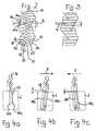
- FIG. 2 shows a section of a profile block 6 from FIG. 1.
- the profile block 6 shown schematically there has a plurality of sipes 10.
- the sipes 10 divide the profile block 6 into profile block elements 12.
- the sipes 10 of the profile block 6 have, in contrast to the conventional sinusoidal sipes of the profile block shown in Fig. 3 according to the prior art each in the range of outer edges 13, 14 of the profile block 6 beginning or ending section with normal, sinusoidal half-waves 15, 16 with normal amplitude, while approximately in the middle of the profile block 6 along a longitudinal axis A - A 'only indicated a half-wave 17 is located with greatly excessive amplitude.
- L1 denotes the length between the amplitude maximum of the sipe 10a and the bending axis B
- L2 denotes the length between the amplitude minimum of the sipe 10b and the bending axis B
- L1 L2 for the ratio L1: L2.
- LK in Fig. 3 denotes the conventional length; this is the symmetrical aspect ratio between maximum and minimum amplitude to the normal axis N again. For the ratio of L2 to LK: L2> LK.
- FIGS. 4 a - c the profile block 6 is shown in a schematic side view in various operating states.
- Fig. 4a shows the profile block in the unloaded state;
- Fig. 4b shows him on traction on snow.
- the arrow F indicates the direction of the acting forces; the "V" of the half-wave 17 points with its tip to the direction of travel.
- the angle ⁇ becomes particularly large by the ratio L1 ⁇ L2. It sets a strong edge effect, since the element 12 is soft by the displacement of the bending axis B.
- Fig. 4c the tread block 6 is shown when braking on ice, so with opposite direction of force F.
- the ratio L1: L2 is reversed, it applies when braking L1> L2.
- the rigidity of the tread block element 12 is also greater due to the larger lever L2; the angle ⁇ becomes smaller, less element deformation takes place. This results in a lower edge effect, it forms a stiff wiper edge, which is understood that this edge wipes the surface water on the ice similar to a windscreen wiper blade and thereby allows a rubber-ice friction.
- FIGS. 5 a and 5 b the situation from FIG. 4 a is again based on an enlarged, not to scale three-dimensional simulation of three profile block elements 12 a - c given. It can be seen there in particular that the edges 18 are lifted high in the area of the half-wave 17 at the inlet into the landslide and can dig deep into the snow.
Landscapes
- Engineering & Computer Science (AREA)
- Mechanical Engineering (AREA)
- Tires In General (AREA)
- Transition And Organic Metals Composition Catalysts For Addition Polymerization (AREA)
Description
- Die Erfindung betrifft einen Fahrzeugluftreifen zum Einsatz unter winterlichen Fahrbedingungen gemäß dem Oberbegriff des Patentanspruchs 1.
- Gattungsgemäße Fahrzeugluftreifen, nämlich Winterreifen, sind beispielsweise aus der DE 196 35 147 A1 und der US 6,250,354 B1 bekannt. Üblicherweise weisen derartige Winterreifen Umfangsrillen, Schrägrillen und/oder Querrillen auf, welche eine Vielzahl von Profilblöcken trennen, welche bei moderneren Konzeptionen schräg zur Umfangsrichtung des Reifen und schräg zueinander verlaufen bzw. angeordnet sind, so dass das Laufstreifenprofil insgesamt pfeilartig untergliedert ist. Die Profilblockelemente innerhalb der Laufstreifenmitte, wie auch die Profilblöcke im Schulterbereich des Reifens weisen Feineinschnitte auf, welche fälschlicherweise als Lamellen bezeichnet werden. Diese Feineinschnitte weisen in der US 6,250,354 in Aufsicht auf das Laufstreifenprofil einen symmetrischen zickzackförmigen Verlauf auf. Bekannt sind ebenfalls wellenförmige oder gerade Verläufe. Im Radialschnitt können die Feineinschnitte gerade, schräg oder dreidimensional sein. Verlaufen die Feineinschnitte wellenförmig, so ist die Wellenlinie zumeist sinusförmig mit konstanter Amplitude und Wellenlänge, auch wenn bereits in der DE 35 40 669 A1 Feineinschnitte beschrieben wurden, deren Amplitude zur Mitte eines Profilblocks hin zunimmt, während in der DE 35 40 668 C2 Feineinschnitte vorgeschlagen wurden, deren Wellenlänge im Zentrum des Profilblocks kleiner ist als an seinen Kanten. In der US 5 873 399 A sind symmetrische Feineinschnitte beschrieben, die im randlichen Bereich eine kleine Wellenlänge mit kleiner Amplitude aufweisen, während diese im mittigen Bereich eine große Wellenlänge mit großer Amplitude aufweisen.
- Durch die Feineinschnitte entstehen beim Betrieb des Reifens eine Vielzahl von sich öffnenden und wieder schließenden Kanten und Spalten, welche sich beim Fahren auf Schnee und Eis in die derart ausgebildete Fahrbahnoberfläche einkrallen und ein sicheres Fahrverhalten unter winterlichen Bedingungen ermöglichen sollen.
- Die von zwei Feineinschnitten eingeschlossenen Profilblockelemente weisen Kanten auf, welche sich in Schnee und Eis einkrallen und hierdurch die Wintertauglichkeit des Reifens ermöglichen. Zwischen zwei Feineinschnitten liegt die Haupt- oder Biegeachse des Profilblockelements, wobei bei Feineinschnitten mit sinusartigem Wellenzug die Biegeachse in der Mitte des Profilblockelements liegt. Diese Biegeachse ist insbesondere beim Einrollen eines Profilblockelements in den Latsch wichtig für den Grad der Öffnung der Feineinschnitte und für das Entstehen des sogenannten Kanteneffekts. Eine symmetrische Ausgestaltung der Feineinschnitte und der Biegeachse ist insofern vorteilhaft, als hierdurch auch eine Symmetrie in beide Drehrichtungen des Reifens ermöglicht wird, was insbesondere für Reifen wünschenswert ist, die nicht drehsinngebunden sind, bei denen also bei der Montage am Fahrzeug nicht auf einen vorgeschriebenen Drehsinn geachtet werden muß. Aber eine symmetrische Ausgestaltung der Feineinschnitte bewirkt ebenfalls, dass sich beim Bremsen und beim Beschleunigen gleichartige Kanten ausbilden, die den unterschiedlichen Erfordernissen beim Bremsen und Beschleunigen nur bedingt gerecht werden.
- Profilblöcke mit Feineinschnitten haben sich seit langem insbesondere für Winterreifen bewährt. Dennoch können bisherige Lösungen nicht in allen Punkten befriedigen. Insbesondere in Bezug auf das Traktions- und Bremsvermögen von Winterreifen ist noch Raum für Verbesserungen. Bislang versuchte man, den Kanteneffekt und die Anzahl wirksamer Kanten der Profilblockelemente durch Erhöhung der Anzahl der Feineinschnitte, Ausbildung von produktionstechnisch aufwendigen dreidimensionalen Strukturen an den vertikalen Kanten der Profilblockelemente und andere Maßnahmen zu erhöhen.
- Entsprechend ist Aufgabe vorliegender Erfindung die Verbesserung von bekannten Winterreifen hinsichtlich der Wintereigenschaften und des Vermögens des Übertragens von Traktions- und Bremskräften, sowie der Verbesserung der Ausgestaltung wirksamer Kanten der Profilblockelemente.
- Diese Aufgabe wird erfindungsgemäß mit einem Reifen gelöst, welcher die Merkmale des Patentanspruchs 1 aufweist.
- Bei der Ausgestaltung eines Fahrzeugluftreifens gemäß Patentanspruch 1 wird die Aufgabe also dadurch gelöst, dass wenigstens zwei Feineinschnitte jeweils eine Wellenform aufweisen, welche an einer Stelle in einer Halbwelle eine stark überhöhte Amplitude aufweist, wobei die Halbwellen mit stark überhöhter Amplitude der Feineinschnitte miteinander fluchten.
- Mit dieser Lösung entfernt sich der Erfinder bewußt von herkömmlichen Ansätzen, nach denen versucht wurde, den Wellenzug der Feineinschnitte möglichst konstant und symmetrisch zu halten. Der Erfinder hat nämlich herausgefunden, dass sich die Wintereigenschaften mit seiner Lösung deutlich verbessern lassen, weil hierdurch die Lage der Haupt- und Biegeachse in einem Profilblockelement zu einer Feineinschnittkante hin verlegt wird, wodurch die Steifigkeit und das Biegeverhalten des Profilblockelements positiv verändert und optimiert werden. Hierdurch entsteht ein drehrichtungsabhängiges Laufstreifenprofil, wodurch sich weitere positive Gestaltungsmöglichkeiten ergeben.
- Da zwei gleich ausgebildete Feineinschnitte miteinander fluchten, d.h., da die Halbwellen mit stark überhöhter Amplitude auf gleicher Linie senkrecht zur Hauptachse des jeweiligen Feineinschnitts liegen, entsteht in diesem Bereich eine Verzahnung zweier Profilblockelemente, welche stärker ist als in den Bereichen außerhalb der genannten Halbwelle. Diese Verzahnung bewirkt eine stärkere Verzahnung der Profilblockelemente untereinander, wodurch größere Kräfte längs der Hauptachse übertragen werden können. Hierdurch wird das Lenkansprechen und die Fahrstabilität verbessert.
- Weitere Vorteile und Ausgestaltungen der Erfindung, welche Gegenstand der weiteren Patentansprüche sind, werden im Folgenden anhand von Ausführungsbeispielen in der Beschreibung und in der Zeichnung näher dargestellt. In der Zeichnung ist
- Fig. 1
- die Aufsicht auf ein Ausführungsbeispiel eines Laufstreifenprofils eines erfindungsgemäßen Fahrzeugluftreifens,
- Fig. 2
- eine Prinzipskizze eines einzelnen Profilblocks gemäß der Erfindung,
- Fig. 3
- eine Prinzipskizze eines Profilblocks nach dem Stand der Technik,
- Fig. 4 a - c
- der Profilblock aus Fig. 2 von der Seite, und
- Fig. 5 a, b
- Elemente eines erfindungsgemäßen Profilblocks im Betrieb in dreidimensionaler Ansicht
- In Figur 1 ist ein erstes Ausführungsbeispiel eines Laufstreifenprofils 1 eines Winterreifens in maßstabsgetreuer Darstellung gezeigt. Der Laufstreifen 1 weist Längsrillen 2 und eine Reihe von Schrägrillen 3, 4 auf, durch welche der Laufstreifen in eine Reihe von Profilblöcken 5 bis 7 und in axial außenseitig angeordnete Schulterblockreihen 8 und 9 unterteilt ist. Die Profilblöcke 5 bis 7 und die Schulterblockreihen 8 und 9 weisen Feineinschnitte 10,11 auf, wobei Feineinschnitte 11 der Profilblöcke 5, 7 sowie der Schulterblockreihen 8, 9 einen sinuswellenförmigen Verlauf entsprechend dem bekannten Stand der Technik aufweisen, während Feineinschnitte 10 des Profilblocks 6 einen von der Sinuskurve abweichenden Verlauf gemäß der Erfindung aufweisen.
- Der prinzipielle Aufbau des Profilblocks 6 gemäß der Erfindung ist in den Figuren 2, 4 bis 5 näher dargestellt, während Figur 3 zum besseren Verständnis den normalen Aufbau gemäß dem Stand der Technik darstellt.
- In Figur 2 ist ein Ausschnitt eines Profilblocks 6 aus Fig. 1 dargestellt. Der dort schematisch dargestellte Profilblock 6 weist mehrere Feineinschnitte 10 auf. Die Feineinschnitte 10 unterteilen den Profilblock 6 in Profilblockelemente 12. Die Feineinschnitte 10 des Profilblock 6 weisen im Gegensatz zu den herkömmlichen sinusförmigen Feineinschnitte des in Fig. 3 dargestellten Profilblocks gemäß dem Stand der Technik jeweils einen im Bereich von Außenkanten 13, 14 des Profilblocks 6 beginnenden bzw. endenden Abschnitt mit normalen, sinusartigen Halbwellen 15, 16 mit Normalamplitude auf, während sich etwa in der Mitte des Profilblocks 6 entlang einer nur angedeuteten Längsachse A - A' eine Halbwelle 17 mit stark überhöhter Amplitude befindet. Diese Halbwellen bilden durch ihre Flucht zur Achse A - A' ein "V" und eine an dieser Stelle besondere Verzahnung. Durch die Halbwelle 17 verschiebt sich eine Haupt- oder Biegeachse B von der in Fig. 3 dargestellten Normalachse N zur Kante 18 eines Profilblockelements 12.
- Mit L1 ist in Fig. 2 die Länge zwischen Amplitudenmaximum des Feineinschnitts 10a und der Biegeachse B, und mit L2 die Länge zwischen Amplitudenminimum des Feineinschnitts 10b und der Biegeachse B bezeichnet, wobei für das Verhältnis L1 : L2 gilt: L1 < L2. Mit LK in Fig. 3 ist die konventionelle Länge bezeichnet; diese gibt das symmetrische Längenverhältnis zwischen maximaler und minimaler Amplitude zur Normalachse N wieder. Für das Verhältnis von L2 zu LK gilt: L2 > LK.
- In den Fig. 4 a - c ist der Profilblock 6 in schematischer Seitenansicht in verschiedenen Betriebszuständen dargestellt. Fig. 4a zeigt den Profilblock im unbelasteten Zustand; Fig. 4b zeigt ihn bei Traktion auf Schnee. Der Pfeil F deutet die Richtung der einwirkenden Kräfte an; das "V" der Halbwelle 17 deutet mit seiner Spitze zur Fahrtrichtung. Durch Verschiebung der Biegeachse B stellt sich die Kante 18 hoch und kann so besonders tief in den Schnee eingreifen. Der Winkel α wird durch das Verhältnis L1 < L2 besonders groß. Es stellt sich ein starker Kanteneffekt ein, da das Element 12 durch die Verschiebung der Biegeachse B weich ist.
- In Fig. 4 c ist der Profilblock 6 beim Bremsen auf Eis dargestellt, also mit entgegen gesetzter Kraftrichtung F. Hier nun wird auch das Verhältnis L1 : L2 umgekehrt, es gilt beim Bremsen L1 > L2. Die Steifigkeit des Profilblockelements 12 wird aufgrund des größeren Hebels L2 ebenfalls größer; der Winkel β wird kleiner, es findet eine geringere Elementverformung statt. Hierdurch entsteht ein geringerer Kanteneffekt, es bildet sich eine steife Wischkante aus, worunter verstanden wird, dass diese Kante ähnlich einem Scheibenwischerblatt das Oberflächenwasser auf dem Eis wegwischt und hierdurch eine Gummi-Eis-Reibung ermöglicht.
- In den Fig. 5 a und 5 b ist die Situation aus Fig. 4a anhand einer vergrößerten, nicht maßstabgerechten dreidimensionalen Simulation dreier Profilblockelemnte 12 a -c wieder gegeben. Zu erkennen ist dort insbesondere, dass die Kanten 18 im Bereich der Halbwelle 17 beim Einlauf in den Latsch hoch gehoben werden und sich tief in Schnee einkrallen können.
-
- 1
- Laufstreifen
- 2
- Längsrille
- 3
- Schrägrille
- 4
- Schrägrille
- 5
- Profilblock
- 6
- Profilblock
- 7
- Profilblock
- 8
- Schulterblockreihe
- 9
- Schulterblockreihe
- 10
- Feineinschnitt
- 11
- Feineinschnitt
- 12
- Profilblockelement
- 13
- Außenkante
- 14
- Außenkante
- 15
- Halbwelle
- 16
- Halbwelle
- 17
- Halbwelle
- 18
- Elementkante
- A-A'
- Längsachse
- B
- Biegeachse
- N
- Normalachse
- F
- Kraftrichtung
Claims (10)
- Fahrzeugluftreifen insbesondere zum Einsatz unter winterlichen Fahrbedingungen, mit einem Laufstreifenprofil (1), welches durch Längsrillen (2) und Schrägrillen (3, 4) in von einander getrennte Profilblöcke (5 - 9) untergliedert ist, wobei die Profilblöcke (5 - 9) im Wesentlichen parallel zueinander angeordnete Feineinschnitte (10, 10a, 10b, 11) in Wellenform aufweisen, welche einen Profilblock in Profilblockelemente (12) unterteilen, dadurch gekennzeichnet, dass wenigstens zwei Feineinschnitte (10; 10a, 10b) jeweils eine Wellenform aufweisen, welche an einer Stelle in einer Halbwelle (17) eine stark überhöhte Amplitude aufweist, wobei die Halbwellen (17) mit stark überhöhter Amplitude der Feineinschnitte (10;10a, 10b) miteinander fluchten.
- Fahrzeugluftreifen nach Anspruch 1, dadurch gekennzeichnet, dass das Amplitudenverhältnis der Amplitude der normalen Halbwellen (15, 16) zur Amplitude der Halbwelle (17) mit überhöhter Amplitude zwischen 1 : 2 und 1 : 5 beträgt.
- Fahrzeugluftreifen nach einem der vorangegangenen Ansprüche, dadurch gekennzeichnet, dass sich die Halbwelle (17) mit stark überhöhter Amplitude im Mittenbereich (A - A') eines Profilblocks (5-9) befindet.
- Fahrzeugluftreifen nach einem der vorangegangenen Ansprüche, dadurch gekennzeichnet, dass sich die Halbwelle (17) mit stark überhöhter Amplitude im Kantenbereich (13, 14) eines Profilblocks (5-9) befindet.
- Fahrzeugluftreifen nach einem der vorangegangenen Ansprüche, dadurch gekennzeichnet, dass die Breite der Feineinschnitte (10, 11) 0,1 mm bis 5 mm, insbesondere 0,3 - 0,8 mm beträgt.
- Fahrzeugluftreifen nach einem der vorangegangenen Ansprüche, dadurch gekennzeichnet, dass die Breite der Profilblockelemente (12) 2 mm bis 50 mm, insbesondere 3-10 mm beträgt.
- Fahrzeugluftreifen nach einem der vorangegangenen Ansprüche, dadurch gekennzeichnet, dass die Feineinschnitte (10, 11) jeweils im Winkel zu den Profilblockkanten (13, 14) angeordnet sind und diese schneiden.
- Fahrzeugluftreifen nach einem der vorangegangenen Ansprüche, dadurch gekennzeichnet, dass der Laufstreifen (1) drehrichtungsgebunden ist, wobei das Wellental der Halbwelle (17) mit stark überhöhter Amplitude in Fahrtrichtung ausgerichtet ist.
- Fahrzeugluftreifen nach einem der vorangegangenen Ansprüche, dadurch gekennzeichnet, dass in einem Feinschnitt (10; 10a; 10b) das Verhältnis der Anzahl von normalen Halbwellen (15, 16) zur Anzahl von Halbwellen (17) mit überhöhter Amplitude zwischen 2 : 1 und 20 : 1 beträgt.
- Fahrzeugluftreifen nach einem der Ansprüche 1-9, dadurch gekennzeichnet, dass ausschließlich der mittig über den Reifenumfang umlaufende Profilblock (6) wenigstens zwei Feineinschnitte (10; 10a, 10b) mit jeweils einer Wellenform aufweist, welche an einer Stelle in einer Halbwelle (17) eine stark überhöhte Amplitude aufweist, wobei die Halbwellen (17) der Feineinschnitte (10; 10a, 10b) mit stark überhöhter Amplitude miteinander fluchten.
Applications Claiming Priority (2)
| Application Number | Priority Date | Filing Date | Title |
|---|---|---|---|
| DE10301012 | 2003-01-13 | ||
| DE10301012A DE10301012A1 (de) | 2003-01-13 | 2003-01-13 | Fahrzeugluftreifen insbesondere zum Einsatz unter winterlichen Fahrbedingungen |
Publications (2)
| Publication Number | Publication Date |
|---|---|
| EP1437238A1 EP1437238A1 (de) | 2004-07-14 |
| EP1437238B1 true EP1437238B1 (de) | 2007-02-21 |
Family
ID=32478223
Family Applications (1)
| Application Number | Title | Priority Date | Filing Date |
|---|---|---|---|
| EP03104430A Expired - Lifetime EP1437238B1 (de) | 2003-01-13 | 2003-11-27 | Fahrzeugluftreifen insbesondere zum Einsatz unter winterlichen Bedingungen |
Country Status (4)
| Country | Link |
|---|---|
| EP (1) | EP1437238B1 (de) |
| AT (1) | ATE354482T1 (de) |
| DE (2) | DE10301012A1 (de) |
| NO (1) | NO323735B1 (de) |
Cited By (2)
| Publication number | Priority date | Publication date | Assignee | Title |
|---|---|---|---|---|
| EP4497609A1 (de) * | 2023-07-28 | 2025-01-29 | Toyo Tire Corporation | Luftreifen |
| EP4574462A1 (de) * | 2023-12-20 | 2025-06-25 | Continental Reifen Deutschland GmbH | Fahrzeugreifen |
Families Citing this family (4)
| Publication number | Priority date | Publication date | Assignee | Title |
|---|---|---|---|---|
| JP4397956B1 (ja) * | 2008-07-02 | 2010-01-13 | 横浜ゴム株式会社 | 空気入りタイヤ |
| JP6043048B2 (ja) * | 2011-03-01 | 2016-12-14 | 株式会社ブリヂストン | 空気入りタイヤ |
| JP5620529B2 (ja) * | 2013-02-08 | 2014-11-05 | 株式会社ブリヂストン | 空気入りタイヤ |
| DE102014215251A1 (de) * | 2014-08-01 | 2016-02-04 | Continental Reifen Deutschland Gmbh | Fahrzeugluftreifen |
Family Cites Families (10)
| Publication number | Priority date | Publication date | Assignee | Title |
|---|---|---|---|---|
| FR2544251B1 (fr) * | 1983-04-12 | 1986-05-09 | Michelin & Cie | Elements en relief d'une bande de roulement pour pneumatique comportant des incisions a trace ondule ou brise |
| DE3540669A1 (de) * | 1985-11-16 | 1987-05-21 | Continental Gummi Werke Ag | Fahrzeugluftreifen |
| DE3540668C2 (de) * | 1985-11-16 | 1994-09-22 | Continental Ag | Fahrzeugluftreifen |
| JP3426384B2 (ja) * | 1995-02-28 | 2003-07-14 | 株式会社ブリヂストン | 氷雪走行に適した空気入りタイヤ |
| JP4035177B2 (ja) * | 1995-12-14 | 2008-01-16 | 株式会社ブリヂストン | スタッドレス空気入りタイヤ |
| AT404342B (de) * | 1996-03-29 | 1998-10-27 | Semperit Ag | Fahrzeugluftreifen |
| DE19635147A1 (de) * | 1996-08-30 | 1998-03-05 | Continental Ag | Fahrzeugluftreifen |
| JP3337415B2 (ja) * | 1998-03-04 | 2002-10-21 | 住友ゴム工業株式会社 | 氷上走行に適した空気入りタイヤ |
| JPH11310013A (ja) * | 1998-04-28 | 1999-11-09 | Toyo Tire & Rubber Co Ltd | 空気入りラジアルタイヤ |
| DE10101507A1 (de) * | 2001-01-12 | 2002-08-01 | Continental Ag | Fahrzeugreifen |
-
2003
- 2003-01-13 DE DE10301012A patent/DE10301012A1/de not_active Withdrawn
- 2003-11-27 EP EP03104430A patent/EP1437238B1/de not_active Expired - Lifetime
- 2003-11-27 AT AT03104430T patent/ATE354482T1/de not_active IP Right Cessation
- 2003-11-27 DE DE50306574T patent/DE50306574D1/de not_active Expired - Lifetime
-
2004
- 2004-01-06 NO NO20040039A patent/NO323735B1/no not_active IP Right Cessation
Cited By (2)
| Publication number | Priority date | Publication date | Assignee | Title |
|---|---|---|---|---|
| EP4497609A1 (de) * | 2023-07-28 | 2025-01-29 | Toyo Tire Corporation | Luftreifen |
| EP4574462A1 (de) * | 2023-12-20 | 2025-06-25 | Continental Reifen Deutschland GmbH | Fahrzeugreifen |
Also Published As
| Publication number | Publication date |
|---|---|
| EP1437238A1 (de) | 2004-07-14 |
| NO323735B1 (no) | 2007-07-02 |
| NO20040039L (no) | 2004-07-14 |
| DE10301012A1 (de) | 2004-07-22 |
| ATE354482T1 (de) | 2007-03-15 |
| DE50306574D1 (de) | 2007-04-05 |
Similar Documents
| Publication | Publication Date | Title |
|---|---|---|
| DE69611341T2 (de) | Kraftfahrzeug-Luftreifen mit einem Laufflächenprofil besonders geeignet zum Laufen auf schneebedeckten Strassenoberflächen | |
| DE69925175T2 (de) | Luftreifen | |
| EP1529660A1 (de) | Laufflächenprofil eines Winterreifens | |
| EP2222481A1 (de) | Fahrzeugluftreifen | |
| EP0671288A1 (de) | Fahrzeugluftreifen | |
| DE102020214363A1 (de) | Fahrzeugluftreifen | |
| DE102010060946A1 (de) | Fahrzeugluftreifen | |
| DE102008044921A1 (de) | Fahrzeugluftreifen | |
| EP3421264B1 (de) | Fahrzeugluftreifen | |
| DE10101507A1 (de) | Fahrzeugreifen | |
| DE19705156C2 (de) | Fahrzeugluftreifen | |
| EP1428688B1 (de) | Fahrzeugluftreifen zum Einsatz unter winterlichen Fahrbedingungen | |
| EP3034332B1 (de) | Fahrzeugluftreifen | |
| EP3446892B1 (de) | Fahrzeugluftreifen | |
| EP2785537B1 (de) | Fahrzeugluftreifen | |
| EP1437238A1 (de) | Fahrzeugluftreifen insbesondere zum Einsatz unter winterlichen Bedingungen | |
| DE10352146A1 (de) | Fahrzeugluftreifen | |
| DE19826927B4 (de) | Radialluftreifen | |
| WO2019020231A1 (de) | Laufstreifenprofil eines fahrzeugreifens | |
| WO2019048092A1 (de) | Fahrzeugluftreifen | |
| EP4321350B1 (de) | Fahrzeugluftreifen | |
| EP0958945B1 (de) | Fahrzeugreifen | |
| EP1616721A1 (de) | Fahrzeugluftreifen | |
| DE102018206902A1 (de) | Fahrzeugluftreifen | |
| DE102022211764A1 (de) | Fahrzeugreifen |
Legal Events
| Date | Code | Title | Description |
|---|---|---|---|
| PUAI | Public reference made under article 153(3) epc to a published international application that has entered the european phase |
Free format text: ORIGINAL CODE: 0009012 |
|
| AK | Designated contracting states |
Kind code of ref document: A1 Designated state(s): AT BE BG CH CY CZ DE DK EE ES FI FR GB GR HU IE IT LI LU MC NL PT RO SE SI SK TR |
|
| AX | Request for extension of the european patent |
Extension state: AL LT LV MK |
|
| 17P | Request for examination filed |
Effective date: 20050114 |
|
| AKX | Designation fees paid |
Designated state(s): AT BE BG CH CY CZ DE DK EE ES FI FR GB GR HU IE IT LI LU MC NL PT RO SE SI SK TR |
|
| AXX | Extension fees paid |
Extension state: LV Payment date: 20050114 Extension state: AL Payment date: 20050114 Extension state: MK Payment date: 20050114 Extension state: LT Payment date: 20050114 |
|
| GRAP | Despatch of communication of intention to grant a patent |
Free format text: ORIGINAL CODE: EPIDOSNIGR1 |
|
| GRAS | Grant fee paid |
Free format text: ORIGINAL CODE: EPIDOSNIGR3 |
|
| GRAA | (expected) grant |
Free format text: ORIGINAL CODE: 0009210 |
|
| AK | Designated contracting states |
Kind code of ref document: B1 Designated state(s): AT BE BG CH CY CZ DE DK EE ES FI FR GB GR HU IE IT LI LU MC NL PT RO SE SI SK TR |
|
| AX | Request for extension of the european patent |
Extension state: AL LT LV MK |
|
| PG25 | Lapsed in a contracting state [announced via postgrant information from national office to epo] |
Ref country code: NL Free format text: LAPSE BECAUSE OF FAILURE TO SUBMIT A TRANSLATION OF THE DESCRIPTION OR TO PAY THE FEE WITHIN THE PRESCRIBED TIME-LIMIT Effective date: 20070221 Ref country code: SI Free format text: LAPSE BECAUSE OF FAILURE TO SUBMIT A TRANSLATION OF THE DESCRIPTION OR TO PAY THE FEE WITHIN THE PRESCRIBED TIME-LIMIT Effective date: 20070221 Ref country code: IE Free format text: LAPSE BECAUSE OF FAILURE TO SUBMIT A TRANSLATION OF THE DESCRIPTION OR TO PAY THE FEE WITHIN THE PRESCRIBED TIME-LIMIT Effective date: 20070221 Ref country code: DK Free format text: LAPSE BECAUSE OF FAILURE TO SUBMIT A TRANSLATION OF THE DESCRIPTION OR TO PAY THE FEE WITHIN THE PRESCRIBED TIME-LIMIT Effective date: 20070221 |
|
| REG | Reference to a national code |
Ref country code: GB Ref legal event code: FG4D Free format text: NOT ENGLISH |
|
| REG | Reference to a national code |
Ref country code: CH Ref legal event code: EP |
|
| REF | Corresponds to: |
Ref document number: 50306574 Country of ref document: DE Date of ref document: 20070405 Kind code of ref document: P |
|
| REG | Reference to a national code |
Ref country code: IE Ref legal event code: FG4D Free format text: LANGUAGE OF EP DOCUMENT: GERMAN |
|
| PG25 | Lapsed in a contracting state [announced via postgrant information from national office to epo] |
Ref country code: SE Free format text: LAPSE BECAUSE OF FAILURE TO SUBMIT A TRANSLATION OF THE DESCRIPTION OR TO PAY THE FEE WITHIN THE PRESCRIBED TIME-LIMIT Effective date: 20070521 |
|
| PG25 | Lapsed in a contracting state [announced via postgrant information from national office to epo] |
Ref country code: BG Free format text: LAPSE BECAUSE OF EXPIRATION OF PROTECTION Effective date: 20070522 |
|
| PG25 | Lapsed in a contracting state [announced via postgrant information from national office to epo] |
Ref country code: ES Free format text: LAPSE BECAUSE OF FAILURE TO SUBMIT A TRANSLATION OF THE DESCRIPTION OR TO PAY THE FEE WITHIN THE PRESCRIBED TIME-LIMIT Effective date: 20070601 |
|
| PG25 | Lapsed in a contracting state [announced via postgrant information from national office to epo] |
Ref country code: PT Free format text: LAPSE BECAUSE OF FAILURE TO SUBMIT A TRANSLATION OF THE DESCRIPTION OR TO PAY THE FEE WITHIN THE PRESCRIBED TIME-LIMIT Effective date: 20070723 |
|
| LTIE | Lt: invalidation of european patent or patent extension |
Effective date: 20070221 |
|
| NLV1 | Nl: lapsed or annulled due to failure to fulfill the requirements of art. 29p and 29m of the patents act | ||
| ET | Fr: translation filed | ||
| GBV | Gb: ep patent (uk) treated as always having been void in accordance with gb section 77(7)/1977 [no translation filed] |
Effective date: 20070221 |
|
| REG | Reference to a national code |
Ref country code: IE Ref legal event code: FD4D |
|
| PG25 | Lapsed in a contracting state [announced via postgrant information from national office to epo] |
Ref country code: GB Free format text: LAPSE BECAUSE OF FAILURE TO SUBMIT A TRANSLATION OF THE DESCRIPTION OR TO PAY THE FEE WITHIN THE PRESCRIBED TIME-LIMIT Effective date: 20070221 Ref country code: SK Free format text: LAPSE BECAUSE OF FAILURE TO SUBMIT A TRANSLATION OF THE DESCRIPTION OR TO PAY THE FEE WITHIN THE PRESCRIBED TIME-LIMIT Effective date: 20070221 |
|
| PLBE | No opposition filed within time limit |
Free format text: ORIGINAL CODE: 0009261 |
|
| STAA | Information on the status of an ep patent application or granted ep patent |
Free format text: STATUS: NO OPPOSITION FILED WITHIN TIME LIMIT |
|
| PG25 | Lapsed in a contracting state [announced via postgrant information from national office to epo] |
Ref country code: CZ Free format text: LAPSE BECAUSE OF FAILURE TO SUBMIT A TRANSLATION OF THE DESCRIPTION OR TO PAY THE FEE WITHIN THE PRESCRIBED TIME-LIMIT Effective date: 20070221 Ref country code: RO Free format text: LAPSE BECAUSE OF FAILURE TO SUBMIT A TRANSLATION OF THE DESCRIPTION OR TO PAY THE FEE WITHIN THE PRESCRIBED TIME-LIMIT Effective date: 20070221 |
|
| 26N | No opposition filed |
Effective date: 20071122 |
|
| PG25 | Lapsed in a contracting state [announced via postgrant information from national office to epo] |
Ref country code: GR Free format text: LAPSE BECAUSE OF FAILURE TO SUBMIT A TRANSLATION OF THE DESCRIPTION OR TO PAY THE FEE WITHIN THE PRESCRIBED TIME-LIMIT Effective date: 20070522 Ref country code: IT Free format text: LAPSE BECAUSE OF FAILURE TO SUBMIT A TRANSLATION OF THE DESCRIPTION OR TO PAY THE FEE WITHIN THE PRESCRIBED TIME-LIMIT Effective date: 20070221 |
|
| BERE | Be: lapsed |
Owner name: CONTINENTAL A.G. Effective date: 20071130 |
|
| PG25 | Lapsed in a contracting state [announced via postgrant information from national office to epo] |
Ref country code: MC Free format text: LAPSE BECAUSE OF NON-PAYMENT OF DUE FEES Effective date: 20071130 |
|
| PG25 | Lapsed in a contracting state [announced via postgrant information from national office to epo] |
Ref country code: LI Free format text: LAPSE BECAUSE OF NON-PAYMENT OF DUE FEES Effective date: 20071130 Ref country code: CH Free format text: LAPSE BECAUSE OF NON-PAYMENT OF DUE FEES Effective date: 20071130 |
|
| REG | Reference to a national code |
Ref country code: CH Ref legal event code: PL |
|
| PG25 | Lapsed in a contracting state [announced via postgrant information from national office to epo] |
Ref country code: BE Free format text: LAPSE BECAUSE OF NON-PAYMENT OF DUE FEES Effective date: 20071130 |
|
| PG25 | Lapsed in a contracting state [announced via postgrant information from national office to epo] |
Ref country code: EE Free format text: LAPSE BECAUSE OF FAILURE TO SUBMIT A TRANSLATION OF THE DESCRIPTION OR TO PAY THE FEE WITHIN THE PRESCRIBED TIME-LIMIT Effective date: 20070221 |
|
| PG25 | Lapsed in a contracting state [announced via postgrant information from national office to epo] |
Ref country code: AT Free format text: LAPSE BECAUSE OF NON-PAYMENT OF DUE FEES Effective date: 20071127 |
|
| PGFP | Annual fee paid to national office [announced via postgrant information from national office to epo] |
Ref country code: FR Payment date: 20081113 Year of fee payment: 6 |
|
| PG25 | Lapsed in a contracting state [announced via postgrant information from national office to epo] |
Ref country code: CY Free format text: LAPSE BECAUSE OF FAILURE TO SUBMIT A TRANSLATION OF THE DESCRIPTION OR TO PAY THE FEE WITHIN THE PRESCRIBED TIME-LIMIT Effective date: 20070221 |
|
| PG25 | Lapsed in a contracting state [announced via postgrant information from national office to epo] |
Ref country code: LU Free format text: LAPSE BECAUSE OF NON-PAYMENT OF DUE FEES Effective date: 20071127 |
|
| PG25 | Lapsed in a contracting state [announced via postgrant information from national office to epo] |
Ref country code: TR Free format text: LAPSE BECAUSE OF FAILURE TO SUBMIT A TRANSLATION OF THE DESCRIPTION OR TO PAY THE FEE WITHIN THE PRESCRIBED TIME-LIMIT Effective date: 20070221 Ref country code: HU Free format text: LAPSE BECAUSE OF FAILURE TO SUBMIT A TRANSLATION OF THE DESCRIPTION OR TO PAY THE FEE WITHIN THE PRESCRIBED TIME-LIMIT Effective date: 20070822 |
|
| REG | Reference to a national code |
Ref country code: FR Ref legal event code: ST Effective date: 20100730 |
|
| PG25 | Lapsed in a contracting state [announced via postgrant information from national office to epo] |
Ref country code: FR Free format text: LAPSE BECAUSE OF NON-PAYMENT OF DUE FEES Effective date: 20091130 |
|
| PGFP | Annual fee paid to national office [announced via postgrant information from national office to epo] |
Ref country code: DE Payment date: 20151130 Year of fee payment: 13 |
|
| REG | Reference to a national code |
Ref country code: DE Ref legal event code: R119 Ref document number: 50306574 Country of ref document: DE |
|
| PG25 | Lapsed in a contracting state [announced via postgrant information from national office to epo] |
Ref country code: DE Free format text: LAPSE BECAUSE OF NON-PAYMENT OF DUE FEES Effective date: 20170601 |
|
| PGFP | Annual fee paid to national office [announced via postgrant information from national office to epo] |
Ref country code: FI Payment date: 20181121 Year of fee payment: 16 |
|
| REG | Reference to a national code |
Ref country code: FI Ref legal event code: MAE |
|
| PG25 | Lapsed in a contracting state [announced via postgrant information from national office to epo] |
Ref country code: FI Free format text: LAPSE BECAUSE OF NON-PAYMENT OF DUE FEES Effective date: 20191127 |