EP1437265A1 - Aufpralldämpfer - Google Patents
Aufpralldämpfer Download PDFInfo
- Publication number
- EP1437265A1 EP1437265A1 EP20030258254 EP03258254A EP1437265A1 EP 1437265 A1 EP1437265 A1 EP 1437265A1 EP 20030258254 EP20030258254 EP 20030258254 EP 03258254 A EP03258254 A EP 03258254A EP 1437265 A1 EP1437265 A1 EP 1437265A1
- Authority
- EP
- European Patent Office
- Prior art keywords
- energy absorber
- impact energy
- concave
- convex portions
- thickness
- Prior art date
- Legal status (The legal status is an assumption and is not a legal conclusion. Google has not performed a legal analysis and makes no representation as to the accuracy of the status listed.)
- Withdrawn
Links
- 239000006096 absorbing agent Substances 0.000 title claims abstract description 129
- 239000002655 kraft paper Substances 0.000 claims abstract description 14
- 239000000463 material Substances 0.000 claims description 49
- 239000011888 foil Substances 0.000 claims description 24
- 229910052782 aluminium Inorganic materials 0.000 claims description 14
- XAGFODPZIPBFFR-UHFFFAOYSA-N aluminium Chemical compound [Al] XAGFODPZIPBFFR-UHFFFAOYSA-N 0.000 claims description 14
- 238000004804 winding Methods 0.000 claims description 3
- 238000004519 manufacturing process Methods 0.000 abstract description 3
- 239000005030 aluminium foil Substances 0.000 abstract description 2
- 229910052751 metal Inorganic materials 0.000 abstract description 2
- 239000002184 metal Substances 0.000 abstract description 2
- 238000012360 testing method Methods 0.000 description 16
- 239000011295 pitch Substances 0.000 description 14
- 230000000052 comparative effect Effects 0.000 description 5
- 239000000853 adhesive Substances 0.000 description 4
- 230000001070 adhesive effect Effects 0.000 description 4
- 210000003128 head Anatomy 0.000 description 4
- 238000011056 performance test Methods 0.000 description 3
- 230000006835 compression Effects 0.000 description 2
- 238000007906 compression Methods 0.000 description 2
- 210000001061 forehead Anatomy 0.000 description 2
- 239000011521 glass Substances 0.000 description 2
- 238000009434 installation Methods 0.000 description 2
- 230000035939 shock Effects 0.000 description 2
- XEEYBQQBJWHFJM-UHFFFAOYSA-N Iron Chemical compound [Fe] XEEYBQQBJWHFJM-UHFFFAOYSA-N 0.000 description 1
- 239000002390 adhesive tape Substances 0.000 description 1
- 239000004411 aluminium Substances 0.000 description 1
- 230000004323 axial length Effects 0.000 description 1
- 230000004888 barrier function Effects 0.000 description 1
- 238000010276 construction Methods 0.000 description 1
- 230000000694 effects Effects 0.000 description 1
- 238000005516 engineering process Methods 0.000 description 1
- 238000002474 experimental method Methods 0.000 description 1
- 230000005484 gravity Effects 0.000 description 1
- 238000012986 modification Methods 0.000 description 1
- 230000004048 modification Effects 0.000 description 1
- 230000002093 peripheral effect Effects 0.000 description 1
- 230000001681 protective effect Effects 0.000 description 1
- 230000003068 static effect Effects 0.000 description 1
Images


Classifications
-
- B—PERFORMING OPERATIONS; TRANSPORTING
- B60—VEHICLES IN GENERAL
- B60R—VEHICLES, VEHICLE FITTINGS, OR VEHICLE PARTS, NOT OTHERWISE PROVIDED FOR
- B60R21/00—Arrangements or fittings on vehicles for protecting or preventing injuries to occupants or pedestrians in case of accidents or other traffic risks
- B60R21/02—Occupant safety arrangements or fittings, e.g. crash pads
- B60R21/04—Padded linings for the vehicle interior ; Energy absorbing structures associated with padded or non-padded linings
-
- F—MECHANICAL ENGINEERING; LIGHTING; HEATING; WEAPONS; BLASTING
- F16—ENGINEERING ELEMENTS AND UNITS; GENERAL MEASURES FOR PRODUCING AND MAINTAINING EFFECTIVE FUNCTIONING OF MACHINES OR INSTALLATIONS; THERMAL INSULATION IN GENERAL
- F16F—SPRINGS; SHOCK-ABSORBERS; MEANS FOR DAMPING VIBRATION
- F16F7/00—Vibration-dampers; Shock-absorbers
- F16F7/12—Vibration-dampers; Shock-absorbers using plastic deformation of members
-
- B—PERFORMING OPERATIONS; TRANSPORTING
- B60—VEHICLES IN GENERAL
- B60R—VEHICLES, VEHICLE FITTINGS, OR VEHICLE PARTS, NOT OTHERWISE PROVIDED FOR
- B60R21/00—Arrangements or fittings on vehicles for protecting or preventing injuries to occupants or pedestrians in case of accidents or other traffic risks
- B60R21/02—Occupant safety arrangements or fittings, e.g. crash pads
- B60R21/04—Padded linings for the vehicle interior ; Energy absorbing structures associated with padded or non-padded linings
- B60R2021/0435—Padded linings for the vehicle interior ; Energy absorbing structures associated with padded or non-padded linings associated with the side or roof pillars
-
- B—PERFORMING OPERATIONS; TRANSPORTING
- B60—VEHICLES IN GENERAL
- B60R—VEHICLES, VEHICLE FITTINGS, OR VEHICLE PARTS, NOT OTHERWISE PROVIDED FOR
- B60R21/00—Arrangements or fittings on vehicles for protecting or preventing injuries to occupants or pedestrians in case of accidents or other traffic risks
- B60R21/02—Occupant safety arrangements or fittings, e.g. crash pads
- B60R21/04—Padded linings for the vehicle interior ; Energy absorbing structures associated with padded or non-padded linings
- B60R2021/0442—Padded linings for the vehicle interior ; Energy absorbing structures associated with padded or non-padded linings associated with the roof panel
-
- B—PERFORMING OPERATIONS; TRANSPORTING
- B60—VEHICLES IN GENERAL
- B60R—VEHICLES, VEHICLE FITTINGS, OR VEHICLE PARTS, NOT OTHERWISE PROVIDED FOR
- B60R21/00—Arrangements or fittings on vehicles for protecting or preventing injuries to occupants or pedestrians in case of accidents or other traffic risks
- B60R21/02—Occupant safety arrangements or fittings, e.g. crash pads
- B60R21/04—Padded linings for the vehicle interior ; Energy absorbing structures associated with padded or non-padded linings
- B60R21/0428—Padded linings for the vehicle interior ; Energy absorbing structures associated with padded or non-padded linings associated with the side doors or panels, e.g. displaced towards the occupants in case of a side collision
Definitions
- the present invention relates to an impact energy absorber, in particular, although not exclusively, for absorbing an impact load applied to an automotive body or the like.
- a conventional impact energy absorber used for a motor vehicle is a pipe-shaped element having a circular cross section, and is disposed between an automotive body panel and a cabin interior panel.
- the impact energy absorber is constructed so that if an unexpected accident occurs when the motor vehicle is running and hence the passenger hits against the body panel, the aforementioned circular pipe is collapsed and plastically deformed, by which the impact energy is absorbed.
- This energy absorber 51 is constructed so that kraft papers are lapped on the outside and inside of an aluminum foil, which is an intermediate layer material, these materials are formed into a pipe shape, and spiral corrugated portions are formed with equal pitches in a peripheral wall portion to provide flexibility.
- the energy absorber 51 is formed so as to have a square or rectangular cross-sectional shape (hereinafter, this energy absorber is referred to as a rectangular energy absorber).
- FIG. 10A shows a case where the above-described rectangular impact energy absorber 51 is used
- FIG. 10B shows a case where an impact energy absorber 52 having a circular cross section is used as a comparative example.
- the energy absorber 52 is a flexible pipe having a cross section of a perfect circle, in which the outside diameter thereof is the same dimension as the outside width of one side of the rectangular energy absorber 51, and the axial length, the thickness of intermediate layer material and the like, the pitch and the number of turns of spiral shape are also the same as those of the rectangular energy absorber 51.
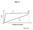
- the deformation mode suitable for performance as an impact energy absorber is where, as in the case of the rectangular energy absorber 51, the deformation amount is small at high loads from the early stage, and when a load higher than a fixed value is applied, the deformation amount increases suddenly.
- the rectangular impact energy absorber tends to be disposed in not only a front roof but also a side roof, a rear roof, and other various portions. Therefore, the demand for it is increasing not only on the continent of North America but also in Japan.
- the rectangular impact energy absorber must be formed into a rectangular shape after an energy absorber having a circular cross section has been manufactured. Therefore, special equipment and technology are needed, and much time and labor are consumed, which leads to a high manufacturing cost for the energy absorber.
- the rectangular impact energy absorber has a directional property such that when a load is applied in the direction perpendicular to the opposed surfaces, high impact energy is absorbed, but when a load is applied in the diagonal direction, the performance is inferior.
- the present invention has been made in view of the above situation, and accordingly preferred embodiments of the present invention seek to provide an impact energy absorber that is lower in cost and easier to manufacture than the rectangular impact energy absorber, can absorb high energy like the rectangular impact energy absorber, and can provide its performance even if a load is applied from a direction over a wide angle range.
- the present invention provides an impact energy absorber having flexibility, which is a circular pipe formed by lapping band-shaped materials in a spiral form and formed with concave and convex portions in a circumferential portion in a spiral or annular form, the pipe including an aluminum band material with a thickness of 0.07 to 0.12 mm, the vertical width of the concave and convex portions being 2.0 to 3.2 mm, and the pitch of the concave and convex portions being 1.4 to 2.0 mm, to absorb energy by plastic deformation of the flexible pipe when impact energy is applied.
- an impact energy absorber having flexibility which is a circular pipe formed by lapping band-shaped materials in a spiral form and formed with concave and convex portions in a circumferential portion in a spiral or annular form, and is disposed between a body panel and an interior member of a motor vehicle, the pipe including an aluminum band material with a thickness of 0.07 to 0.12 mm, the vertical width of the concave and convex portions being 2.0 to 3.2 mm, and the pitch of the concave and convex portions being 1.4 to 2.0 mm, to absorb energy by plastic deformation of said flexible pipe when impact energy is applied.
- the flexible pipe may be formed by lapping a kraft paper on the outside and inside of a band-shaped aluminium foil and by winding these materials.
- the kraft paper may have an arbitrary, appropriate thickness, for example, a thickness of 0.2 mm.
- the pipe may comprise an aluminium band material with a thickness of 0.10 to 0.12 mm, the vertical width of said concave and convex portions being 2.3 to 3.2 mm, the pitch of said concave and convex portions being 1.5 to 1.7 mm, and the outside diameter being 20 to 30 mm, to absorb energy by plastic deformation of said flexible pipe.
- a conventional impact energy absorber having a circular cross section has a linear relationship between load and deformation amount in the load performance test.
- the inventor found that the circular impact energy absorber in accordance with the present invention has the same relationship between load and deformation amount as that of the rectangular impact energy absorber in the load performance test under specific conditions, that is, by increasing the apparent thickness of energy absorber and by specifying the vertical width and pitch of the concave and convex portions.
- FIGS. 1 and 2 show an impact energy absorber 1 in accordance with the present invention.
- FIG. 1 is a perspective view of the energy absorber 1
- FIG. 2A is a front view of the pipe-shaped energy absorber 1, viewed from an axial direction
- FIG. 2B is a partially broken side view thereof, viewed from a circumferential direction
- FIG. 2C is an enlarged sectional view of a portion indicated by arrow mark X in FIG. 2B.
- This energy absorber 1 is a flexible pipe having a circular cross section.
- the energy absorber 1 consists of three layers of an inner layer material 2, an intermediate layer material 3, and an outer layer material 4 in that order from the inside.
- an inner layer material 2 and the outer layer material 4 a kraft paper is used, and as the intermediate layer material, a metal sheet, for example, iron foil or aluminum foil is used.
- a hard aluminum foil is used as the intermediate layer material.
- the inner layer material 2, the intermediate layer material 3, and the outer layer material 4 are formed by winding band-shaped materials in a spiral form.
- the energy absorber 1 can be formed so as to extend in the axial direction according to the length of each material. Also, the energy absorber 1 can be cut to an appropriate length. Such an energy absorber can easily be bent at an angle larger than 90 degrees or into an S shape.
- the requirements for occurrence of rectangular wave characteristics of the impact energy absorber 1 are as follows: the outside diameter D of the impact energy absorber 1 is 20 to 50 mm, the pitch p from the valley of the concave portion 5 to the valley of the adjacent concave portion 5 is 1.4 to 2 mm, and the vertical width (apparent thickness, see FIG. 2C) T of the concave and convex portions 5 and 6 is 2.3 to 3.2 mm.
- a band-shaped foil with a thickness of 0.07 to 0.12 mm and a width of 28 to 45 mm is used.
- the number of band-shaped foils for the intermediate layer material 3 may be one, or may be two or three lapped on each other.
- the intermediate layer material 3 is formed by overlapping the end portions of band-shaped foils with each other by about 5 mm when the foil is wound.
- the preferred thickness of the intermediate layer material 3 before the concave and convex portions 5 and 6 are formed is 0.1 to 0.3 mm.
- a kraft paper with a thickness (thickness before the concave and convex portions 5 and 6 are formed) of 0.2 to 0.4 mm and a width of 48 to 60 mm is used.
- FIG. 3 shows a setup for a dynamic load characteristic test for the above-described impact energy absorber in conformity with FMVSS201 regulations.
- a jig 11 of a square shape in cross section is fixed on a wall 10
- the energy absorber 1 is fixed to the jig 11 by fixing means such as a double-faced adhesive tape.
- Example 1 having the largest apparent thickness T showed a rectangular shape such that the deformation amount was small from the early stage at high loads, and when a load higher than a fixed value was applied, the deformation amount increased suddenly.
- Examples 2 and 3 showed better rectangular shape with increasing apparent thickness T.
- the reason why the energy absorber 1 formed with the concave and convex portions 5 and 6 absorbs a larger amount of energy than the ordinary pipe is thought to be that not only plastic deformation occurs in the radial direction but also plastic deformation occurs in the axial direction of the pipe as well due to the stretch of the concave and convex portions 5 and 6.
- the reason why the energy absorber having a larger apparent thickness T absorbs higher impact energy is thought to be that when the shapes of the concave and convex portions 5 and 6 collapse, the deformation amount of absorber having a larger vertical width of the concave and convex portions is larger than that of absorber having a smaller vertical width of the concave and convex portions, or the deformation amount in the axial direction is large, by which a larger amount of energy is absorbed. Also, it is thought that the increase in thickness of the intermediate layer material 3 contributes to absorbing higher energy. Thus, the energy absorber 1 can absorb high energy even though it has a small diameter.
- the energy absorber using two band-shaped aluminum foils as the intermediate layer material 3 absorbs a larger amount of energy than the energy absorber using one aluminum foil with a thickness equal to the total thickness of the two foils.
- the impact energy absorber 1 absorbs or relaxes impact energy when an impact force is applied to a vehicle body at the time of collision of motor vehicle.
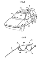
- the energy absorber 1 may be disposed in a front pillar 22, center pillar 23, front and rear door shoulder portions 24 and 25, front and rear door lower portions 26 and 27, front roof rail portion 28, side roof rail portion 29, rear header rail portion 30, and the like of a vehicle body 21. If a sliding roof is installed, the energy absorber may be disposed around the sliding roof 31.
- the shape of the impact energy absorber 1, which is preferable as the impact energy absorber used for a motor vehicle is as follows: the outside diameter D is 20 to 30 mm, the pitch p from the valley of the concave portion 5 to the valley of the adjacent concave portion 5 is 1.5 to 1.7 mm, and the vertical width (apparent thickness) T of the concave and convex portions 5 and 6 is 2.3 to 3.0 mm.
- a band-shaped foil with a thickness of 0.1 to 0.12 mm and a width of 28 to 35 mm is used.
- the number of band-shaped foils for the intermediate layer material 3 is two or three lapped on each other.
- a kraft paper with a thickness of 0.2 mm and a width of 48 to 60 mm is used.
- the preferred shape of the impact energy absorber 1 is given in Table 3. Size (outside diameter) Corrugate pitch Apparent tube thickness (T) Al foil Number of Al foils Kraft paper ⁇ 20 - ⁇ 30 1.5mm - 1.7mm (58 to 66 peaks / L100) 2.3mm - 3.0mm t0.10mm - t0.12mm w28mm-w35mm 2 to 3 t0.2mm w48mm - w60mm
- the shape of the impact energy absorber 1, which is optimal as the impact energy absorber used for a motor vehicle is as follows: the outside diameter D is 23 to 26 mm, the pitch p from the valley of the concave portion 5 to the valley of the adjacent concave portion 5 is 1.5 to 1.6 mm, and the vertical width (apparent thickness) T of the concave and convex portions 5 and 6 is 2.7 to 2.9 mm.
- a band-shaped foil with a thickness of 0.1 to 0.12 mm and a width of 35 mm is used as the intermediate layer material 3.
- the number of band-shaped foils for the intermediate layer material 3 is two lapped on each other.
- a kraft paper with a thickness of 0.2 mm and a width of 60 mm is used for the inner layer material 2 and the outer layer material 4.
- the optimum shape of the impact energy absorber 1 for a motor vehicle is given in Table 4.
- Size (outside diameter) Corrugate pitch
- Apparent tube thickness (T) Al foil Number of Al foils Kraft paper ⁇ 23 - ⁇ 26 1.5mm - 1.6mm (62 to 66 peaks / L100) 2.7mm - 2.9mm t0.10mm - t0.12mm w35mm 2 t0.2mm w60mm
- FIGS. 6 to 8 show states in which the energy absorber : is actually disposed in the vehicle body 21 of a motor vehicle.
- the front roof rail portion 28 is provided above a windshield glass 32 of the vehicle body 21, and the front roof rail portion 28 forms a closed cross section by means of a roof outer panel 28a and a roof inner panel 28b.
- the impact energy absorber 1 is disposed on the rear side of this closed cross section.
- the energy absorber 1 can be bonded directly to the inner panel 28b easily with an adhesive 33. In installation, a sponge-form cushioning material may be installed windingly around the energy absorber 1. Since the energy absorber 1 is flexible, it can be installed to a curved portion. The energy absorber 1 is hidden by an interior panel 34 that covers the roof on the cabin side.
- the energy absorber 1 is disposed between the interior panel 34 and the inner panel 28b in this manner, when the passenger's forehead hits the front roof rail portion 28, the energy absorber 1 is subjected to plastic deformation, by which impact energy can be absorbed. Also, since the energy absorber 1 has a circular cross section, it has a high directional property and hence can absorb sufficient impact energy over a wide angle range.
- FIG. 7 shows a state in which the impact energy absorber 1 is provided in the side roof rail portion 29 of the vehicle body 21.
- the side roof rail portion 29 is provided at the side of the ceiling portion of the vehicle body 21, and forms a closed cross section by means of a side outer panel 35a and a side inner panel 35b. Flanges 35c formed at the upper ends of these panels 35a and 35b are joined to the roof outer panel 28a.
- the impact energy absorber 1 is disposed on the cabin side of this closed cross section. The energy absorber 1 is bonded directly to the roof outer panel 28a and the side inner panel 35b with the adhesive 33. The energy absorber 1 is hidden by the interior panel 34 that covers the roof on the cabin side.
- the energy absorber 1 When the side of the head of the passenger hits the side roof rail portion 29, the energy absorber 1 is subjected to plastic deformation, by which impact energy can be absorbed.
- the rear header rail portion 30 is provided above a rear glass 36 of the vehicle body 21, and the rear header rail portion 30 forms a closed cross section by means of the roof outer panel 28a and the roof inner panel 28b.
- the impact energy absorber 1 is disposed on the front side of this closed cross section.
- the energy absorber 1 can be bonded directly to the inner panel 28b with the adhesive 33.
- the energy absorber 1 is hidden by the interior panel 34 that covers the roof on the cabin side.
- the energy absorber 1 When the back of the head of the passenger hits the rear header rail portion 30, the energy absorber 1 is subjected to plastic deformation, by which impact energy can be absorbed.
- the energy absorber 1 can be disposed in the front pillar 22, center pillar 23, front and rear door shoulder portions 24 and 25, and front and rear door lower portions 26 and 27, and around the sliding roof 31 of the vehicle body 21 by almost the same way.
- the energy absorber 1 having a circular cross section in accordance with the embodiment of the present invention, when an impact force is applied to the vehicle body 21, the energy absorber 1 is subjected to plastic deformation, by which impact energy is absorbed, and hence the passenger's burden of shock can be alleviated.
- the cost can be reduced significantly because there is no need for forming the cross section into a rectangular shape unlike the conventional rectangular energy absorber 1.
- the energy absorber 1 is disposed at positions shown in FIG. 5.
- the installation position of the energy absorber 1 is not limited to these positions, and the energy absorber 1 can be disposed, for example, in an apron side panel and front panel of an engine room to achieve the same effect. In such a case, an energy absorber that is harder and can absorb higher impact energy than the impact energy absorber 1 disposed in the cabin is used.
- the energy absorber 1 is installed with an adhesive in the above-described embodiment, the energy absorber 1 may be fixed to the panel by installing clips on the energy absorber 1, or may be installed by a clip band.
- the impact energy absorber 1 is formed with the concave and convex portions 5 and 6 around entire circumference over the total length in the above-described embodiment, the concave and convex portions 5 and 6 may be formed with a clearance being provided partially.
- the impact energy absorber 1 can be not only used for a motor vehicle but also for a protective barrier against motor vehicle on a road, which is other than the vehicle body of motor vehicle.
- the impact energy absorber in accordance with the present invention is a circular pipe formed by lapping band-shaped materials in a spiral form.
- the pipe includes an aluminum band material with a thickness of 0.07 to 0.12 mm, the vertical width of the concave and convex portions is 2.0 to 3.2 mm, and the pitch of the concave and convex portions is 1.4 to 2.0 mm.
- the energy absorber in accordance with the present invention can be used in a curved portion.
Landscapes
- Engineering & Computer Science (AREA)
- General Engineering & Computer Science (AREA)
- Mechanical Engineering (AREA)
- Body Structure For Vehicles (AREA)
- Vibration Dampers (AREA)
Applications Claiming Priority (2)
| Application Number | Priority Date | Filing Date | Title |
|---|---|---|---|
| JP2003001653 | 2003-01-08 | ||
| JP2003001653A JP2004210201A (ja) | 2003-01-08 | 2003-01-08 | 衝撃エネルギー吸収材 |
Publications (1)
| Publication Number | Publication Date |
|---|---|
| EP1437265A1 true EP1437265A1 (de) | 2004-07-14 |
Family
ID=32501200
Family Applications (1)
| Application Number | Title | Priority Date | Filing Date |
|---|---|---|---|
| EP20030258254 Withdrawn EP1437265A1 (de) | 2003-01-08 | 2003-12-31 | Aufpralldämpfer |
Country Status (3)
| Country | Link |
|---|---|
| US (1) | US20040140169A1 (de) |
| EP (1) | EP1437265A1 (de) |
| JP (1) | JP2004210201A (de) |
Cited By (2)
| Publication number | Priority date | Publication date | Assignee | Title |
|---|---|---|---|---|
| ES2254022A1 (es) * | 2004-11-16 | 2006-06-01 | Mimcord, S.A. | Recubrimiento reciclable y biodegradable para superficies interiores de vehiculos. |
| EP1679234A1 (de) * | 2004-12-16 | 2006-07-12 | Ohtsuka Co., Ltd. | Energie-Verzehranordnung für ein Fahrzeug |
Families Citing this family (6)
| Publication number | Priority date | Publication date | Assignee | Title |
|---|---|---|---|---|
| US7963378B2 (en) * | 2006-08-10 | 2011-06-21 | O-Flex Group, Inc. | Corrugated tubular energy absorbing structure |
| CN102226490B (zh) * | 2011-05-11 | 2013-07-24 | 中国核电工程有限公司 | 波纹形吸能装置及采用这种吸能装置的防甩击限制件 |
| US8668247B2 (en) * | 2012-04-23 | 2014-03-11 | GM Global Technology Operations LLC | Magnesium-composite structures with enhanced design |
| WO2015031983A1 (en) * | 2013-09-06 | 2015-03-12 | Tsai Jack Yiyo | Anchorage connector for a safety system |
| US9550466B2 (en) * | 2014-03-05 | 2017-01-24 | Toyota Motor Engineering & Manufacturing North America, Inc. | Morphing energy absorber system for a vehicle assembly |
| CN115667057B (zh) * | 2020-06-04 | 2025-11-14 | 昂登坦汽车工程有限责任公司 | 车辆结构 |
Citations (5)
| Publication number | Priority date | Publication date | Assignee | Title |
|---|---|---|---|---|
| US5680886A (en) * | 1996-07-15 | 1997-10-28 | Ohtsuka Co., Ltd. | Impact energy absorber |
| EP0888952A1 (de) * | 1997-07-01 | 1999-01-07 | Ohtsuka Co., Ltd. | Vorrichtung zur Aufnahme von Aufprallenergie |
| JPH1170886A (ja) * | 1997-07-01 | 1999-03-16 | Ootsuka:Kk | 衝撃エネルギー吸収材及びその吸収構造 |
| EP0962342A2 (de) * | 1998-06-03 | 1999-12-08 | Ohtsuka Co., Ltd. | Stossenergieaufnehmende Luftzufuhrleitung |
| US6293614B1 (en) * | 1998-05-08 | 2001-09-25 | Toyota Jidosha Kabushiki Kaisha | Impact energy absorbing structure in upper vehicle body portion and impact energy absorbing member |
Family Cites Families (6)
| Publication number | Priority date | Publication date | Assignee | Title |
|---|---|---|---|---|
| EP0676763B1 (de) * | 1994-07-15 | 1998-01-21 | POZZOLI S.p.A. | Behälter für mehrere Platten, insbesondere kompakte Platten |
| DE19605336A1 (de) * | 1996-02-14 | 1997-08-21 | Polygram Manufacturing & Distr | Gehäuse zur Aufnahme von plattenförmigen Informationsträgern |
| US5782348A (en) * | 1996-06-19 | 1998-07-21 | Alpha Enterprises, Inc. | Multiple disc storage case |
| US5996788A (en) * | 1998-04-01 | 1999-12-07 | Alpha Enterprises, Inc. | Storage container for recorded media |
| AU2001280614A1 (en) * | 2000-07-18 | 2002-01-30 | Nexpak Corporation | Storage container for recorded media |
| US6554132B2 (en) * | 2001-02-20 | 2003-04-29 | Finest Industrial Co., Ltd. | Disk protective enclosure |
-
2003
- 2003-01-08 JP JP2003001653A patent/JP2004210201A/ja active Pending
- 2003-12-31 EP EP20030258254 patent/EP1437265A1/de not_active Withdrawn
-
2004
- 2004-01-07 US US10/752,613 patent/US20040140169A1/en not_active Abandoned
Patent Citations (5)
| Publication number | Priority date | Publication date | Assignee | Title |
|---|---|---|---|---|
| US5680886A (en) * | 1996-07-15 | 1997-10-28 | Ohtsuka Co., Ltd. | Impact energy absorber |
| EP0888952A1 (de) * | 1997-07-01 | 1999-01-07 | Ohtsuka Co., Ltd. | Vorrichtung zur Aufnahme von Aufprallenergie |
| JPH1170886A (ja) * | 1997-07-01 | 1999-03-16 | Ootsuka:Kk | 衝撃エネルギー吸収材及びその吸収構造 |
| US6293614B1 (en) * | 1998-05-08 | 2001-09-25 | Toyota Jidosha Kabushiki Kaisha | Impact energy absorbing structure in upper vehicle body portion and impact energy absorbing member |
| EP0962342A2 (de) * | 1998-06-03 | 1999-12-08 | Ohtsuka Co., Ltd. | Stossenergieaufnehmende Luftzufuhrleitung |
Non-Patent Citations (1)
| Title |
|---|
| PATENT ABSTRACTS OF JAPAN vol. 1999, no. 08 30 June 1999 (1999-06-30) * |
Cited By (3)
| Publication number | Priority date | Publication date | Assignee | Title |
|---|---|---|---|---|
| ES2254022A1 (es) * | 2004-11-16 | 2006-06-01 | Mimcord, S.A. | Recubrimiento reciclable y biodegradable para superficies interiores de vehiculos. |
| ES2254022B1 (es) * | 2004-11-16 | 2007-05-16 | Mimcord, S.A. | Recubrimiento reciclable y biodegradable para superficies interiores de vehiculos. |
| EP1679234A1 (de) * | 2004-12-16 | 2006-07-12 | Ohtsuka Co., Ltd. | Energie-Verzehranordnung für ein Fahrzeug |
Also Published As
| Publication number | Publication date |
|---|---|
| US20040140169A1 (en) | 2004-07-22 |
| JP2004210201A (ja) | 2004-07-29 |
Similar Documents
| Publication | Publication Date | Title |
|---|---|---|
| US5680886A (en) | Impact energy absorber | |
| EP0962342B1 (de) | Stossenergieaufnehmende Luftzufuhrleitung | |
| EP1653114A1 (de) | Stossabsorbierendes glied | |
| US9259995B2 (en) | Energy absorbing component | |
| US6779835B2 (en) | Energy absorbing structure for automobile interior | |
| JP3223896B2 (ja) | 自動車の車体上部の衝撃エネルギ吸収構造 | |
| US20060131902A1 (en) | Impact energy absorbing structure for vehicle | |
| EP1437265A1 (de) | Aufpralldämpfer | |
| US6092555A (en) | Absorbing body and a combination of an absorbing body and vehicle body parts | |
| CN106050381A (zh) | 用于增强碰撞安全性的消声器 | |
| EP0888952A1 (de) | Vorrichtung zur Aufnahme von Aufprallenergie | |
| US5800008A (en) | Vehicle body upper structure of automobile | |
| US6540259B2 (en) | Shock absorbing structure | |
| US12071091B2 (en) | Vehicle door trim | |
| JP3159208B2 (ja) | 中空状の衝撃吸収体の固定構造 | |
| JP3845419B2 (ja) | 衝撃エネルギー吸収材 | |
| JP2001508376A (ja) | 衝撃エネルギー吸収性ボディおよびそのボディと車体パーツとの組合せ | |
| JP2000272448A (ja) | 衝撃エネルギー吸収材 | |
| JPH0858499A (ja) | バンパーステイ | |
| JP3099824B2 (ja) | 2つの衝撃吸収体を車体の構造部材に固定する構造及び衝撃吸収部品 | |
| KR960007329B1 (ko) | 자동차용 조향컬럼의 충격흡수장치 | |
| JP2000177519A (ja) | 衝撃エネルギー吸収材 | |
| JP2001309523A (ja) | 自動車用ワイヤハーネスの保護構造 | |
| JP3361759B2 (ja) | 自動車の車体上部乗員保護構造 | |
| JP3334639B2 (ja) | ドアインパクトビーム |
Legal Events
| Date | Code | Title | Description |
|---|---|---|---|
| PUAI | Public reference made under article 153(3) epc to a published international application that has entered the european phase |
Free format text: ORIGINAL CODE: 0009012 |
|
| AK | Designated contracting states |
Kind code of ref document: A1 Designated state(s): AT BE BG CH CY CZ DE DK EE ES FI FR GB GR HU IE IT LI LU MC NL PT RO SE SI SK TR |
|
| AX | Request for extension of the european patent |
Extension state: AL LT LV MK |
|
| 17P | Request for examination filed |
Effective date: 20041230 |
|
| 17Q | First examination report despatched |
Effective date: 20050221 |
|
| AKX | Designation fees paid |
Designated state(s): DE FR GB |
|
| STAA | Information on the status of an ep patent application or granted ep patent |
Free format text: STATUS: THE APPLICATION IS DEEMED TO BE WITHDRAWN |
|
| 18D | Application deemed to be withdrawn |
Effective date: 20050705 |