EP0962342B1 - Stossenergieaufnehmende Luftzufuhrleitung - Google Patents
Stossenergieaufnehmende Luftzufuhrleitung Download PDFInfo
- Publication number
- EP0962342B1 EP0962342B1 EP98250342A EP98250342A EP0962342B1 EP 0962342 B1 EP0962342 B1 EP 0962342B1 EP 98250342 A EP98250342 A EP 98250342A EP 98250342 A EP98250342 A EP 98250342A EP 0962342 B1 EP0962342 B1 EP 0962342B1
- Authority
- EP
- European Patent Office
- Prior art keywords
- air duct
- air
- vehicle body
- panel
- duct
- Prior art date
- Legal status (The legal status is an assumption and is not a legal conclusion. Google has not performed a legal analysis and makes no representation as to the accuracy of the status listed.)
- Expired - Lifetime
Links
Images

Classifications
-
- B—PERFORMING OPERATIONS; TRANSPORTING
- B60—VEHICLES IN GENERAL
- B60R—VEHICLES, VEHICLE FITTINGS, OR VEHICLE PARTS, NOT OTHERWISE PROVIDED FOR
- B60R19/00—Wheel guards; Radiator guards, e.g. grilles; Obstruction removers; Fittings damping bouncing force in collisions
-
- B—PERFORMING OPERATIONS; TRANSPORTING
- B60—VEHICLES IN GENERAL
- B60H—ARRANGEMENTS OF HEATING, COOLING, VENTILATING OR OTHER AIR-TREATING DEVICES SPECIALLY ADAPTED FOR PASSENGER OR GOODS SPACES OF VEHICLES
- B60H1/00—Heating, cooling or ventilating devices
- B60H1/00507—Details, e.g. mounting arrangements, desaeration devices
- B60H1/00557—Details of ducts or cables
- B60H1/00564—Details of ducts or cables of air ducts
-
- B—PERFORMING OPERATIONS; TRANSPORTING
- B60—VEHICLES IN GENERAL
- B60H—ARRANGEMENTS OF HEATING, COOLING, VENTILATING OR OTHER AIR-TREATING DEVICES SPECIALLY ADAPTED FOR PASSENGER OR GOODS SPACES OF VEHICLES
- B60H1/00—Heating, cooling or ventilating devices
- B60H1/24—Ventilating devices where the heating or cooling is irrelevant
-
- B—PERFORMING OPERATIONS; TRANSPORTING
- B60—VEHICLES IN GENERAL
- B60R—VEHICLES, VEHICLE FITTINGS, OR VEHICLE PARTS, NOT OTHERWISE PROVIDED FOR
- B60R19/00—Wheel guards; Radiator guards, e.g. grilles; Obstruction removers; Fittings damping bouncing force in collisions
- B60R2019/007—Means for adjusting or regulating the crash absorption capacity of the vehicle, e.g. when detecting an impending collision
Definitions
- the present invention relates to an air conditioner which is provided with an air duct which absorb energy caused by an external force applied to a vehicle body and allow the air for an air conditioner to flow as disclosed in DE 2318097.
- An impact energy absorber is known from US5680886.
- An air duct for an automotive air conditioner is usually made of a resin so as to be deformed in some degree because dew condensation is prevented and because the air duct is laid in a limited location where various components within the vehicle are equipped. Also, for a car of a high grade, it is preferable that the cool air of the air conditioner reach the rear seat of a passenger car. Therefore, for example, a one box car is provided with a dual air conditioner so that temperature control for the rear seat can be carried out.
- a body panel such as an outer panel and an inner panel has been reinforced.
- To reinforce the body panel it is necessary only that the thickness of panel is increased. In this case, however, the weight of vehicle body increases by the increased thickness. As a result, the cost of material is increased, and the production cost also goes up.
- the air duct is laid between the outer panel and the inner panel, it sometimes cannot be laid because reinforcements or other reinforcing members are present between these panels. Also, if the air duct is laid with priority, the reinforcing members cannot be arranged effectively, so that the panel cannot sometimes be reinforced effectively. Also, if the air duct is laid between the interior panel and the inner panel, the interior panel portion where the air duct is laid protrudes toward the cabin, which deteriorates the appearance.
- the present invention was made in view of the above situation, and accordingly an object thereof is to provide a shock energy absorbing air duct, in which an air duct for an air conditioner can also be used as a shock absorbing member.
- the present invention provides an air conditioner according to claim 1.
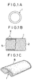
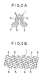
- FIGS. 1A and 1B and FIGS. 2A and 2B show a construction of a pipe-like air duct 1 in accordance with the present invention.
- the cross-sectional shape of the air duct 1 may be circular, polygonal, or other shapes, or may be modified into a pillar shape.
- the figures show an air duct 1 having a circular diametrical cross section.
- the surface shape of the air duct 1 is a composite consisting of four layer materials of an outer layer material 2, two intermediate layer materials 3 and 4, and outer layer material 5 in sequence from the outside.
- the outer layer material 2 and inner layer material 5 are kraft paper
- the intermediate layer materials 3 and 4 are hard aluminum foil.
- These layer materials 2 to 5 are wound spirally, and is formed into a duct shape. Also, they are continuous in the axial direction, and form concaves 6 and convexes 7 in a wave form.
- the crest and trough of the concave 6 and convex 7 have the same shape, and the pitches between the crests are equal.
- the concaves 6 and convexes 7 give flexibility to the air duct 1, so that the air duct 1 can be bent into an arbitrary shape, for example, an S shape.
- the length of the air duct 1 can be changed arbitrarily by cutting.
- the aforementioned composite is not limited to four layers, but may be formed into a plurality of layers other than four layers.
- the aforesaid air duct 1 can be flocked on the whole surface thereof, on the side surface only, or at any location in the lengthwise direction by using a flocking machine (manufactured by Mesac Corp.).
- the flocking principle is as follows:
- piles When piles are placed between an electrode and an earth, the piles are charged and fly toward the earth. If a work is used as the earth, and an adhesive is applied to the work, the piles stick to the work. The ends of the pile are charged positive and negative, respectively, and the central portion is charged zero. Therefore, the pile flies toward the earth charged zero regardless of which end is positive or negative.
- the pile has a thickness of 2 to 20 D (denier) and a length of 0.5 to 4 mm.
- the adhesive is not subject to any special restriction.
- FIG. 1C One example is shown in FIG. 1C.
- piles 8 are planted on one side surface of the duct 1.
- 3 D thick, 1 mm long nylons of 80 to 100 g/m 2 are caused to stick. It is to be noted that other synthetic resin fibers may be used in place of the nylons.
- the duct 1 shown in FIGS. 1A and 1B When the long duct 1 shown in FIGS. 1A and 1B is merely inserted or installed with clips between an outer panel and an inner panel of a vehicle as a shock absorbing member, the duct 1 is brought into contact with the vehicle body by the vibration of the vehicle body during running, by which noise may be generated.
- the piles formed on the surface of the duct 1 can absorb the vibration of vehicle body and prevent the generation of noise.
- Table 1 gives the detailed construction of the air duct 1 having a rectangular cross section.
- Table 1 Type Outside width (mm) Shape Duct material Number of crests per length Weight (g)per 100mm length Kraft paper Hard aluminum Kraft paper 1 20 Square t0.2 ⁇ W60 t0.09 ⁇ W35 t0.2 ⁇ W60 52 11.03 2 26 ⁇ ⁇ t0.1 ⁇ W35 ⁇ 2 ⁇ 52 23.49
- Type 1 is an air duct in which one layer of hard aluminum is wound, while type 2 is an air duct in which two layers thereof are wound. These air ducts 1 were subjected to a load test. The results were that the air duct was collapsed and the inside surfaces thereof touched each other under a load of about 220 kgf for type 1 and about 460 kgf for type 2. These results show that the air duct 1 has a sufficient strength as a shock absorbing member.
- the deformation under a load can be changed by rounding the corners.
- the tuning for strength can be performed by changing the thickness and width of material and the pitch of convexes.
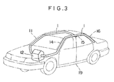
- FIG. 3 shows a general automobile 11.
- a cooling unit 12 for a cooler which is an air conditioner
- the cooling unit 12 is connected with the air ducts 1 for supplying air.
- the air duct 1 is disposed along a side panel of the automobile 11 from the inside of an instrument panel (not shown) where the cooling unit is disposed.
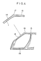
- the air duct 1 is laid from the side panel to a front pillar 14, roof side 15, and rear pillar 16, and disposed in a space formed between an inner panel 17 and an outer panel 18 as shown in FIG. 14.
- the air duct 1 As the air duct 1 is made longer, the flexibility thereof increases, so that the air duct can fit the shape of vehicle body. Therefore, even if the laying location is curved, or has some irregularities, the air duct 1 can be disposed between the panels.
- the air duct 1 is fixed to either of the inner panel 17 and the outer panel 18 by using an adhesive, clip band, or other fixing means. Openings, which are provided at the tip end or intermediate points of the air duct, are connected to blow-off ports on the vehicle body side.
- the air duct 1 is disposed passing through the pillars 14 and 16 and the roof side 15 in the above embodiment, it may be laid passing through a step for a door entrance, that is, a side sill 19.
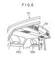
- FIG. 5 shows a one box type automobile 21 having three seats of front, middle, and rear seats.
- the automobile 21 is equipped with a dual air conditioner having two cooling units to each of which an evaporator is disposed.
- one of the cooling units 23 is disposed at the rear part of the ceiling of front seats 22a and 22b.
- Air ducts 1 are, as shown in FIG. 5, laid along the roof sides of the automobile 21 from a connecting port of the cooling unit 23, and disposed so as to extend to the rear.
- the air duct 1 may be laid along a rear pillar.
- the air duct 1 is caused to branch at a center pillar 25 at the halfway point of the roof side 24, disposed downward, and extended rearward at the lower part of a window glass 26.
- the air duct 1 is installed to a panel by being arranged in a space between an outer panel and an inner panel by using an adhesive or other fixing means.
- the air duct 1 can be laid to the rear seat as well as the front and middle seats, and can be connected to blow-off ports disposed in a side panel or the like.
- the air duct 1 may be extended rearward from the other cooling unit disposed at the instrument panel portion. Also, the air duct 1 can be disposed between roof panels or between side panels of a micro-bus or a large-sized bus, in which long air ducts must be laid, not the general one box car.
- the air duct 1 allows the air from the cooling unit (or heater unit) to flow.
- the air duct 1 has a high heat retaining property because it uses kraft paper as the outer layer material 2 and the inner layer material 5, thereby preventing dew condensation caused on the surface of the air duct 1.
- the air duct 1 When an external force is applied to the automobile 11, 21, the air duct 1 is subjected to plastic deformation, so that the energy of the external force is absorbed, by which the deformation of vehicle body and the shock given to the vehicle body can be reduced. Thereupon, the injury of passenger caused by collision is alleviated or prevented.
- the air duct 1 can be installed by being bent so as to fit that shape, so that the air duct 1 has flexibility regardless of the type of vehicle. Therefore, it is unnecessary to form an air duct for each type of vehicle. Because being flexible, the air duct 1 is easy to install, and also light in weight in relation to high strength, so that it does not increase the vehicle weight so much.
- piles may be planted on a pipe.
- the present invention provides an air conditioner for conditioning the air in the vehicle provided with an air duct for allowing air to flow in the vehicle, so as to absorb the energy of an external force owing to the plastic deformation of the air duct when the external force is applied to the vehicle body. Therefore, the air duct not only allows air to flow but also has an effect as a shock energy absorbing member. Specifically, the air duct can absorb the energy caused by an external force applied to the vehicle body without increasing the weight of vehicle so much, so that the shock given to the passenger and the damage to other components equipped on the vehicle can be reduced.
- the vibration of vehicle body during running can be absorbed, so that the occurrence of noise can be prevented.
Landscapes
- Engineering & Computer Science (AREA)
- Mechanical Engineering (AREA)
- Physics & Mathematics (AREA)
- Thermal Sciences (AREA)
- Air-Conditioning For Vehicles (AREA)
- Body Structure For Vehicles (AREA)
- Duct Arrangements (AREA)
Claims (2)
- Klimaanlage zur Klimatisierung der Luft in einem Fahrzeug, die einen Luftkanal besitzt, der sich in einer Durchlassöffnung von einer Luftregeleinheit zu einer in einem Fahrgastraum vorhandenen Luftausblasöffnung erstreckt und es Luft, deren Temperatur in dem Luftregelungsabschnitt eingestellt worden ist, ermöglicht, zur Luftausblasöffnung zu strömen,
dadurch gekennzeichnet, dass der Luftkanal (1) zu einer Rohrform geformt wird, indem Kraftpapier (2,5) spiralförmig sowohl an der Innenseite als auch an der Außenseite eines Aluminiumblechs (3,4) angebracht wird, und dass der Luftkanal (1) flexibel gemacht wird, indem an beiden Oberflächen des Luftkanals (1) in seiner axialen Richtung durch spiralförmige Hohlrundungen (6) und Wölbungen (7) Welligkeiten gebildet werden, und dass sich der Luftkanal (1) entlang einer Blechfläche und entlang eines Seitenblechs der Fahrzeugkarosserie und zwischen einem Innenblech (17) und einem Außenblech (18) der Fahrzeugkarosserie erstreckt, und dass sich der Luftkanal (1) selbst plastisch verformt, um die Stoßenergie einer äußeren Kraft zu absorbieren, wenn eine äußere Kraft auf die Fahrzeugkarosserie einwirkt. - Klimaanlage nach Anspruch 1, bei der die Luftregeleinheit ein Kühlaggregat (23) ist, wobei das Kühlaggregat (23) an einem Deckenabschnitt des Fahrgastraums angebracht ist und sich der Luftkanal (1) entlang einer Dachseite (24) der Fahrzeugkarosserie erstreckt.
Applications Claiming Priority (2)
| Application Number | Priority Date | Filing Date | Title |
|---|---|---|---|
| JP15435798 | 1998-06-03 | ||
| JP10154357A JP3065584B2 (ja) | 1998-06-03 | 1998-06-03 | 衝撃エネルギーを吸収するエアダクト |
Publications (3)
| Publication Number | Publication Date |
|---|---|
| EP0962342A2 EP0962342A2 (de) | 1999-12-08 |
| EP0962342A3 EP0962342A3 (de) | 2002-07-31 |
| EP0962342B1 true EP0962342B1 (de) | 2006-05-10 |
Family
ID=15582399
Family Applications (1)
| Application Number | Title | Priority Date | Filing Date |
|---|---|---|---|
| EP98250342A Expired - Lifetime EP0962342B1 (de) | 1998-06-03 | 1998-09-24 | Stossenergieaufnehmende Luftzufuhrleitung |
Country Status (5)
| Country | Link |
|---|---|
| US (1) | US6123616A (de) |
| EP (1) | EP0962342B1 (de) |
| JP (1) | JP3065584B2 (de) |
| CA (1) | CA2254198C (de) |
| DE (1) | DE69834479T2 (de) |
Families Citing this family (22)
| Publication number | Priority date | Publication date | Assignee | Title |
|---|---|---|---|---|
| JP3578952B2 (ja) * | 1999-11-26 | 2004-10-20 | 本田技研工業株式会社 | 車両のエアダクト及びガーニッシュ構造 |
| DE10007402A1 (de) * | 2000-02-18 | 2001-08-23 | Volkswagen Ag | Vorrichtung zur Belüftung von Fahrzeugscheiben in einem Fahrzeug |
| JP4588172B2 (ja) * | 2000-06-14 | 2010-11-24 | キョーラク株式会社 | 自動車用空調ダクト |
| DE10215347A1 (de) * | 2001-04-10 | 2002-12-12 | Denso Corp | Fahrzeugklimatisierungs-Kanalstruktur, Verfahren zu deren Herstellung und Elektroverkabelungs-Struktur |
| GB0112297D0 (en) * | 2001-05-18 | 2001-07-11 | Bowden S E | Car rear side windows de-mister |
| US6715593B1 (en) * | 2002-09-27 | 2004-04-06 | Ford Global Technologies, Llc | Crush tube assembly |
| US6793572B2 (en) * | 2002-12-21 | 2004-09-21 | James Allen Kodak | Automobile interior heat vent |
| JP2004210201A (ja) * | 2003-01-08 | 2004-07-29 | Ootsuka:Kk | 衝撃エネルギー吸収材 |
| DE10347308A1 (de) * | 2003-10-08 | 2005-05-04 | Volkswagen Ag | Luftversorgungseinrichtung zur Klimatisierung eines Fahrzeuginnenraums eines Fahrzeugs, insbesondere eines Nutzfahrzeuges |
| DE10357086A1 (de) * | 2003-12-06 | 2005-06-30 | Volkswagen Ag | Luftführungskanal für ein Fahrzeug, insbesondere für ein Kraftfahrzeug |
| US7318619B2 (en) * | 2004-01-12 | 2008-01-15 | Munro & Associates | Method and apparatus for reducing drag and noise for a vehicle |
| DE102004039442A1 (de) * | 2004-08-13 | 2006-02-23 | Behr Gmbh & Co. Kg | Belüftungsvorrichtung und Herstellverfahren für eine Belüftungsvorrichtung |
| US7963378B2 (en) * | 2006-08-10 | 2011-06-21 | O-Flex Group, Inc. | Corrugated tubular energy absorbing structure |
| DE102007015114A1 (de) * | 2007-03-29 | 2008-10-02 | Meteor Gummiwerke K.H. Bädje GmbH & Co. KG | Verfahren zur Herstellung eines als Medienleitung nutzbaren Einbaumoduls und Einbaumodul |
| US8109812B2 (en) * | 2007-12-14 | 2012-02-07 | Toyota Motor Engineering & Manufacturing North America, Inc. | Motor vehicle instrument panel assembly having a conduit with a gasket support lip |
| US20090174219A1 (en) * | 2008-01-04 | 2009-07-09 | Foreman Grant G | Vehicle energy absorber structure and method |
| US9027683B2 (en) | 2013-09-27 | 2015-05-12 | Toyota Motor Engineering & Manufacturing North America, Inc. | Elastically deformable air inlets and vehicles incorporating the same |
| US10131206B1 (en) * | 2015-02-27 | 2018-11-20 | Michael W. Kirkpatrick | Air delivery systems and methods for a vehicle passenger compartment |
| EP3112653A1 (de) | 2015-07-03 | 2017-01-04 | MANN+HUMMEL GmbH | Fluidleitung |
| CN106184101B (zh) * | 2016-07-27 | 2019-04-19 | 北京汽车股份有限公司 | 用于车辆的防滚架和具有其的车辆 |
| DE102023200937A1 (de) * | 2023-02-06 | 2024-08-08 | Mahle International Gmbh | Thermomanagementmodul |
| JP7697728B1 (ja) * | 2024-07-19 | 2025-06-24 | 山田ダンボール株式会社 | アルミラミネート紙管及びその製造方法 |
Family Cites Families (16)
| Publication number | Priority date | Publication date | Assignee | Title |
|---|---|---|---|---|
| DE1757002U (de) * | 1955-02-24 | 1957-11-28 | Continental Gummi Werke Ag | Elastisches rohr fuer be- und entlueftungsanlagen, insbesondere in kraftfahrzeugen. |
| US3668039A (en) * | 1970-04-14 | 1972-06-06 | Certain Teed St Gobain | Method for jacketing fibrous ducts |
| DE2318097A1 (de) * | 1973-04-11 | 1974-10-31 | Volkswagenwerk Ag | Ausstroemeranordnung fuer die beschlagentfernung auf einer seitenscheibe eines fahrzeugs |
| JPS6113301Y2 (de) * | 1977-11-07 | 1986-04-24 | ||
| JPS6170335A (ja) * | 1984-09-11 | 1986-04-11 | Toyoda Gosei Co Ltd | エアダクト |
| JPH0664259B2 (ja) * | 1985-10-31 | 1994-08-22 | 日本電信電話株式会社 | 光サ−キユレ−タ |
| DE3637773A1 (de) * | 1986-11-06 | 1988-05-11 | Bayerische Motoren Werke Ag | Karosserie eines personenkraftwagens mit mindestens einem heiz-/klimageraet |
| JPH0575580A (ja) * | 1991-09-11 | 1993-03-26 | Hitachi Telecom Technol Ltd | 回線切替方式 |
| US5325893A (en) * | 1991-10-04 | 1994-07-05 | Tokushu Paper Mfg. Co., Ltd. | Air duct and paper therefor |
| DE4202256C2 (de) * | 1992-01-28 | 1994-11-03 | Beneform Gmbh | Luftkanalanordnung für die Lüftung oder Klimatisierung eines Fahrzeuginnenraumes sowie Verfahren zur Herstellung einer Luftkanalanordnung |
| JPH05286458A (ja) * | 1992-04-09 | 1993-11-02 | Mazda Motor Corp | 自動車の車室前部構造 |
| US5354114A (en) * | 1993-06-21 | 1994-10-11 | Davidson Textron Inc. | Integrated cross car structural duct cluster |
| US5750225A (en) * | 1995-05-26 | 1998-05-12 | Compac Corporation | Laminated vapor barrier |
| JPH09207549A (ja) * | 1996-01-31 | 1997-08-12 | Suzuki Motor Corp | 内装パネル付きダクト |
| JP2990057B2 (ja) * | 1996-03-13 | 1999-12-13 | アイシン軽金属株式会社 | 車体側部のエネルギー吸収構造 |
| DE29611394U1 (de) * | 1996-07-01 | 1996-08-14 | Volkswagen Ag, 38440 Wolfsburg | Strömungskanal für ein Luftführungssystem |
-
1998
- 1998-06-03 JP JP10154357A patent/JP3065584B2/ja not_active Expired - Lifetime
- 1998-09-24 DE DE69834479T patent/DE69834479T2/de not_active Expired - Lifetime
- 1998-09-24 EP EP98250342A patent/EP0962342B1/de not_active Expired - Lifetime
- 1998-10-30 US US09/182,500 patent/US6123616A/en not_active Expired - Fee Related
- 1998-11-17 CA CA002254198A patent/CA2254198C/en not_active Expired - Fee Related
Also Published As
| Publication number | Publication date |
|---|---|
| DE69834479D1 (de) | 2006-06-14 |
| DE69834479T2 (de) | 2006-10-12 |
| CA2254198C (en) | 2002-11-26 |
| US6123616A (en) | 2000-09-26 |
| EP0962342A3 (de) | 2002-07-31 |
| JPH11342722A (ja) | 1999-12-14 |
| JP3065584B2 (ja) | 2000-07-17 |
| EP0962342A2 (de) | 1999-12-08 |
| CA2254198A1 (en) | 1999-12-03 |
Similar Documents
| Publication | Publication Date | Title |
|---|---|---|
| EP0962342B1 (de) | Stossenergieaufnehmende Luftzufuhrleitung | |
| CA2184307C (en) | Impact energy absorber | |
| JP3152267B2 (ja) | 車両のドア構造 | |
| JP3000898B2 (ja) | 自動車の衝撃エネルギ吸収構造 | |
| WO2001089883A1 (de) | Mehrschichtiges formteil | |
| JP2000177516A (ja) | 自動車の車体上部の衝撃エネルギ吸収構造及びエネルギ吸収体 | |
| EP1531115B1 (de) | Bodenplattenstruktur für Kraftfahrzeug | |
| EP3288818B1 (de) | Querträgerbalken | |
| JPH06227333A (ja) | バンパー装置 | |
| US20040140169A1 (en) | Impact energy absorber | |
| CA2219733A1 (en) | Impact energy absorber | |
| US6705669B1 (en) | Energy absorber | |
| US12589812B2 (en) | Cross car beam for a vehicle | |
| JP3159208B2 (ja) | 中空状の衝撃吸収体の固定構造 | |
| EP1440867B1 (de) | Entwurf-Strukturbauteil für Kraftfahrzeug | |
| KR102829855B1 (ko) | 경량 카울 크로스바 | |
| JP3091734B2 (ja) | 衝撃エネルギー吸収材 | |
| JPH05246243A (ja) | 自動車用ドア | |
| CN221138309U (zh) | 一种门槛梁及车辆 | |
| CN216994558U (zh) | 前风挡下横梁和车辆 | |
| JP2000272448A (ja) | 衝撃エネルギー吸収材 | |
| KR950001098Y1 (ko) | 자동차 도어용 임팩트 바(Impact bar) | |
| KR100315354B1 (ko) | 높은 충격 흡수 성능을 가지는 자동차의 필러 | |
| KR100397831B1 (ko) | 자동차 사이드 실의 횡방향 강성 증대 단면구조 | |
| CN119037562A (zh) | 地板总成及车辆 |
Legal Events
| Date | Code | Title | Description |
|---|---|---|---|
| PUAI | Public reference made under article 153(3) epc to a published international application that has entered the european phase |
Free format text: ORIGINAL CODE: 0009012 |
|
| AK | Designated contracting states |
Kind code of ref document: A2 Designated state(s): AT BE CH CY DE DK ES FI FR GB GR IE IT LI LU MC NL PT SE |
|
| AX | Request for extension of the european patent |
Free format text: AL;LT;LV;MK;RO;SI |
|
| 17P | Request for examination filed |
Effective date: 20010125 |
|
| PUAL | Search report despatched |
Free format text: ORIGINAL CODE: 0009013 |
|
| AK | Designated contracting states |
Kind code of ref document: A3 Designated state(s): AT BE CH CY DE DK ES FI FR GB GR IE IT LI LU MC NL PT SE |
|
| AX | Request for extension of the european patent |
Free format text: AL;LT;LV;MK;RO;SI |
|
| AKX | Designation fees paid |
Designated state(s): DE FR GB |
|
| 17Q | First examination report despatched |
Effective date: 20030624 |
|
| GRAP | Despatch of communication of intention to grant a patent |
Free format text: ORIGINAL CODE: EPIDOSNIGR1 |
|
| RTI1 | Title (correction) |
Free format text: SHOCK ENERGY ABSORBING AIR DUCT |
|
| GRAS | Grant fee paid |
Free format text: ORIGINAL CODE: EPIDOSNIGR3 |
|
| GRAA | (expected) grant |
Free format text: ORIGINAL CODE: 0009210 |
|
| RIN1 | Information on inventor provided before grant (corrected) |
Inventor name: OTSUKA, KUNIO |
|
| AK | Designated contracting states |
Kind code of ref document: B1 Designated state(s): DE FR GB |
|
| REG | Reference to a national code |
Ref country code: GB Ref legal event code: FG4D |
|
| REF | Corresponds to: |
Ref document number: 69834479 Country of ref document: DE Date of ref document: 20060614 Kind code of ref document: P |
|
| ET | Fr: translation filed | ||
| PLBE | No opposition filed within time limit |
Free format text: ORIGINAL CODE: 0009261 |
|
| STAA | Information on the status of an ep patent application or granted ep patent |
Free format text: STATUS: NO OPPOSITION FILED WITHIN TIME LIMIT |
|
| 26N | No opposition filed |
Effective date: 20070213 |
|
| PGFP | Annual fee paid to national office [announced via postgrant information from national office to epo] |
Ref country code: GB Payment date: 20090806 Year of fee payment: 12 |
|
| PGFP | Annual fee paid to national office [announced via postgrant information from national office to epo] |
Ref country code: DE Payment date: 20090731 Year of fee payment: 12 |
|
| PGFP | Annual fee paid to national office [announced via postgrant information from national office to epo] |
Ref country code: FR Payment date: 20091012 Year of fee payment: 12 |
|
| GBPC | Gb: european patent ceased through non-payment of renewal fee |
Effective date: 20100924 |
|
| REG | Reference to a national code |
Ref country code: FR Ref legal event code: ST Effective date: 20110531 |
|
| REG | Reference to a national code |
Ref country code: DE Ref legal event code: R119 Ref document number: 69834479 Country of ref document: DE Effective date: 20110401 |
|
| PG25 | Lapsed in a contracting state [announced via postgrant information from national office to epo] |
Ref country code: FR Free format text: LAPSE BECAUSE OF NON-PAYMENT OF DUE FEES Effective date: 20100930 Ref country code: DE Free format text: LAPSE BECAUSE OF NON-PAYMENT OF DUE FEES Effective date: 20110401 |
|
| PG25 | Lapsed in a contracting state [announced via postgrant information from national office to epo] |
Ref country code: GB Free format text: LAPSE BECAUSE OF NON-PAYMENT OF DUE FEES Effective date: 20100924 |