EP1437298A1 - Amortisseur auxiliare pour un train d'atterrissage d'un avion comprenant un balancier, un amortisseur principal et un amortisseur auxiliaire - Google Patents
Amortisseur auxiliare pour un train d'atterrissage d'un avion comprenant un balancier, un amortisseur principal et un amortisseur auxiliaire Download PDFInfo
- Publication number
- EP1437298A1 EP1437298A1 EP20030078797 EP03078797A EP1437298A1 EP 1437298 A1 EP1437298 A1 EP 1437298A1 EP 20030078797 EP20030078797 EP 20030078797 EP 03078797 A EP03078797 A EP 03078797A EP 1437298 A1 EP1437298 A1 EP 1437298A1
- Authority
- EP
- European Patent Office
- Prior art keywords
- strut
- lock
- fluid
- piston
- valve
- Prior art date
- Legal status (The legal status is an assumption and is not a legal conclusion. Google has not performed a legal analysis and makes no representation as to the accuracy of the status listed.)
- Granted
Links
- 239000012530 fluid Substances 0.000 claims abstract description 106
- 238000007667 floating Methods 0.000 claims description 72
- 238000013459 approach Methods 0.000 claims description 6
- 238000013016 damping Methods 0.000 description 4
- 238000007789 sealing Methods 0.000 description 4
- 230000000694 effects Effects 0.000 description 3
- 230000008901 benefit Effects 0.000 description 2
- 230000006835 compression Effects 0.000 description 2
- 238000007906 compression Methods 0.000 description 2
- 230000001419 dependent effect Effects 0.000 description 2
- 238000013461 design Methods 0.000 description 2
- 239000000463 material Substances 0.000 description 2
- 238000012986 modification Methods 0.000 description 2
- 230000004048 modification Effects 0.000 description 2
- 238000012544 monitoring process Methods 0.000 description 2
- 241000251468 Actinopterygii Species 0.000 description 1
- 230000009471 action Effects 0.000 description 1
- 230000008859 change Effects 0.000 description 1
- 238000004891 communication Methods 0.000 description 1
- 238000010276 construction Methods 0.000 description 1
- 230000008602 contraction Effects 0.000 description 1
- 238000012423 maintenance Methods 0.000 description 1
- 230000000750 progressive effect Effects 0.000 description 1
- 238000004904 shortening Methods 0.000 description 1
- 239000007787 solid Substances 0.000 description 1
- 230000003068 static effect Effects 0.000 description 1
- 230000001052 transient effect Effects 0.000 description 1
- 230000007704 transition Effects 0.000 description 1
Images



Classifications
-
- B—PERFORMING OPERATIONS; TRANSPORTING
- B64—AIRCRAFT; AVIATION; COSMONAUTICS
- B64C—AEROPLANES; HELICOPTERS
- B64C25/00—Alighting gear
- B64C25/32—Alighting gear characterised by elements which contact the ground or similar surface
- B64C25/58—Arrangements or adaptations of shock-absorbers or springs
- B64C25/62—Spring shock-absorbers; Springs
-
- B—PERFORMING OPERATIONS; TRANSPORTING
- B64—AIRCRAFT; AVIATION; COSMONAUTICS
- B64C—AEROPLANES; HELICOPTERS
- B64C25/00—Alighting gear
- B64C25/001—Devices not provided for in the groups B64C25/02 - B64C25/68
-
- B—PERFORMING OPERATIONS; TRANSPORTING
- B64—AIRCRAFT; AVIATION; COSMONAUTICS
- B64C—AEROPLANES; HELICOPTERS
- B64C25/00—Alighting gear
- B64C25/32—Alighting gear characterised by elements which contact the ground or similar surface
- B64C25/34—Alighting gear characterised by elements which contact the ground or similar surface wheeled type, e.g. multi-wheeled bogies
-
- F—MECHANICAL ENGINEERING; LIGHTING; HEATING; WEAPONS; BLASTING
- F15—FLUID-PRESSURE ACTUATORS; HYDRAULICS OR PNEUMATICS IN GENERAL
- F15B—SYSTEMS ACTING BY MEANS OF FLUIDS IN GENERAL; FLUID-PRESSURE ACTUATORS, e.g. SERVOMOTORS; DETAILS OF FLUID-PRESSURE SYSTEMS, NOT OTHERWISE PROVIDED FOR
- F15B11/00—Servomotor systems without provision for follow-up action; Circuits therefor
- F15B11/08—Servomotor systems without provision for follow-up action; Circuits therefor with only one servomotor
- F15B11/12—Servomotor systems without provision for follow-up action; Circuits therefor with only one servomotor providing distinct intermediate positions; with step-by-step action
- F15B11/121—Servomotor systems without provision for follow-up action; Circuits therefor with only one servomotor providing distinct intermediate positions; with step-by-step action providing distinct intermediate positions
- F15B11/123—Servomotor systems without provision for follow-up action; Circuits therefor with only one servomotor providing distinct intermediate positions; with step-by-step action providing distinct intermediate positions by means of actuators with fluid-operated stops
Definitions
- the invention relates to a strut which may be used e.g. as an auxiliary strut in semi-levered landing gear for an aircraft. More particularly, the invention relates to a strut having lost motion and lock-up capabilities, comprising:
- the maximum rotation angle of the aircraft during takeoff and landing is limited by a minimum permissible clearance between a rear under portion of the fuselage and the ground. It is known that the takeoff and landing performance of a given aircraft can be enhanced by providing a longer main landing gear about which the aircraft rotates to achieve a nose-up attitude, thereby increasing the maximum rotation angle of the aircraft.
- one of the objectives of aircraft design is to configure the landing gear so that the aircraft fuselage is essentially horizontal during ground operations and has an appropriate sill height for ground servicing. The maximum sill height that is acceptable is dictated by the height of ground equipment that must interface with the aircraft, and thus is generally fixed.
- the maximum allowable sill height is less than what would be desirable from an aircraft performance standpoint, and therefore, merely lengthening the landing gear is not a viable approach to achieving increased maximum rotation angle. Further, landing gear length must be minimized to keep weight to a minimum and to facilitate the stowing of the gear during flight, and hence a wholesale lengthening of the landing gear is undesirable.
- variable-length landing gear capable of assuming a length that is suitable for stowing within the aircraft, and for ground operations while the aircraft is on the ground and stationary, and further capable of assuming a greater length during takeoff and landing operations.
- SLG semi-levered landing gear
- a wheel truck is formed by a bogie beam supporting forward and aft wheels at forward and aft ends thereof, and a main strut of conventional design is pivotally connected to the bogie beam at a main pivot between the forward and aft wheels.
- An additional mechanical linkage is connected at an upper end to the main strut and at a lower end to the bogie beam at an auxiliary pivot spaced from the main pivot for controlling positioning of the bogie beam.
- the additional mechanical linkage enables the bogie beam, under certain conditions, to pivot about the auxiliary pivot rather than the main pivot.
- the bogie beam can be placed in a tilted orientation with the forward wheels off the ground with the aid of the additional mechanical linkage, which prevents the bogie beam from rotating to a horizontal orientation.
- the effective length of the landing gear is increased relative to its length when all wheels are on the ground.
- the aircraft can then rotate to a higher pitch attitude, with the same tail clearance, thus achieving improved takeoff performance.
- a semi-levered landing gear in which the additional mechanical linkage is formed by an auxiliary strut arranged between the main strut and an auxiliary pivot on the bogie beam.
- This auxiliary strut includes a lock-up device allowing the strut to be locked in a intermediate position between its minimum and maximum extension. In this way the bogie beam may pivot about the auxiliary strut and the auxiliary pivot, thus effectively lengthening the landing gear.
- US-A-2,720,865 discloses a hydraulic jack which may be used in e.g. a flap system for an aircraft or a steerable or castoring nosewheel of an aircraft, and which can be locked in an intermediate position between its minimum and maximum stroke.
- This hydraulic jack includes a cylinder having a fluid connection at each end and a hollow piston assembly that is slidable within the cylinder.
- a hollow floating piston is slidably arranged, which is slidable on a plunger that is fixed to an inner end wall of the cylinder and that includes a stop at its outer end.
- an annular protrusion is arranged, which acts as a stop for the piston assembly.
- the piston assembly may be locked in an intermediate position, in which the floating piston is fully extended to the stop of the plunger and the piston assembly is retracted to the stop of the floating piston.
- the other prior art document GB-A-679060 discloses a hydraulic strut for use as a self-centering means for castoring or steerable elements of aircraft landing gear.
- This strut comprises an outer cylinder, a first piston that is slidable within the outer cylinder, and that defines an inner cylinder, and a second piston that is slidable within the inner cylinder.
- the inner and outer cylinder are in fluid communication, and the outer cylinder is further connected to a fluid pressure system.
- This connection is positioned near the outer end of the outer cylinder, so that the introduction of pressurized fluid will act to retract the first piston.
- the fluid connection between the inner and outer cylinder is located near the inner end of the inner cylinder, so that the fluid pressure will act to extend the second piston.
- the present invention has for its object to provide an improved strut having lost motion and lock-up capabilities, which is especially suited for use as an auxiliary strut in a semi-levered landing gear.
- this object is achieved in a strut as defined in the pre-characterizing part of claim 1 in that the piston assembly divides the cylinder barrel into a pair of fluid chambers, the piston assembly defining a fluid path therethrough between the two fluid chambers such that extension and retraction of the piston assembly cause fluid to flow through the fluid path between the chambers; and in that the lock-up device comprises a lock-up valve disposed within the strut and operable to maintain the fluid path open during said portion of a stroke of the piston assembly so as to permit extension of the piston assembly until the strut reaches said predetermined lock-up length, the lock-up valve being operable to close the fluid path at the end of said portion of the stroke so as to substantially prevent further extension of the piston assembly and substantially lock the strut at said predetermined lock-up length.
- a semi-levered landing gear 20 including a strut in accordance with the invention is shown at initial touchdown.
- the gear 20 includes a main strut 22 of suitable construction to absorb and damp transient loads exerted between the gear and the ground during ground operations of an aircraft, and to support the aircraft when stationary on the ground.
- the main strut 22 typically includes a cylinder portion 24 and a piston portion 26 that is telescopingly received in the cylinder portion such that the length of the main strut 22 can vary depending on the amount of load applied to the landing gear in a direction along the axis of the main strut.
- the amount of load applied to the landing gear 20 is relatively small and, accordingly, the length of the main strut 22 is essentially at a maximum.
- the landing gear 20 further includes a wheel truck 28 formed by at least one bogie beam 30 pivotally attached at a main pivot 32 to a lower end of the piston portion 26 of the main strut, and a plurality of wheels rotatably supported by the bogie beam 30, including at least one forward wheel 34 and at least one aft wheel 36 respectively supported at a forward end and an aft end of the bogie beam 30.
- the wheel truck 28 shown in FIG. 1 may include one or more middle wheels 38 located at an intermediate position between the forward and aft wheels.
- the wheel truck of a main landing gear includes at least a pair of forward wheels journaled on an axle and a pair of aft wheels journaled on an axle, and some wheel trucks include a third middle pair of wheels journaled on an axle.
- the present invention is applicable to any wheel truck configuration having at least one wheel supported by a bogie beam at a location that is longitudinally displaced forward or aft of a main pivot at which a main strut is attached to the bogie beam.
- the landing gear 20 also includes an auxiliary strut 40 that is pivotally connected at its upper end to the cylinder portion 24 of the main strut 22 and has its lower end pivotally connected at an auxiliary pivot 42 to the bogie beam 30 at a location forward of the main pivot 32.
- the auxiliary strut 40 is a variable-length device enabling the bogie beam 30 to pivot relative to the main strut 22. Additionally, the auxiliary strut 40 is capable of locking up to a fixed length, when suitably controlled as further described below, such that the bogie beam 30 is forced to pivot about the auxiliary pivot 42 rather than about the main pivot 32 so as to provide a semi-levered function to the landing gear 20.
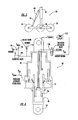
- FIG. 2 depicts one preferred embodiment of the auxiliary strut 40 in greater detail.
- the strut 40 includes a cylinder barrel 44 and a piston assembly 46 slidably received through an open end of the cylinder barrel.
- the piston assembly 46 includes a main piston 48 having at least one lug 50 or other connecting member at its lower end for attachment to the bogie beam of a wheel truck, and a floating piston 52 that is entirely disposed within the cylinder barrel 44 and is slidable with respect to both the cylinder barrel 44 and the main piston 48.
- the floating piston 52 includes an end wall 54 whose outer periphery sealingly engages the inner cylindrical surface 56 of the cylinder barrel 44, and a generally cylindrical portion 58 that is attached to the end wall 54 and extends upwardly therefrom.
- the upper end of the cylindrical portion 58 sealingly engages the inner surface 56 of the cylinder barrel, and is configured such that a lengthwise extending part of the cylindrical portion 58 is spaced radially inwardly of the inner surface 56 of the cylinder barrel so as to create an annular floating piston control chamber 60 between the cylindrical portion 58 and the inner surface 56 of the cylinder barrel.
- the floating piston control chamber 60 can be supplied with pressurized fluid, or alternatively can be evacuated, so as to extend or retract the floating piston 52 within the cylinder barrel 44 so as to vary the length of the strut 40 for rotatably positioning the bogie beam 30 of the landing gear shown in FIG. 1.
- the end wall 54 of the floating piston 52 includes an aperture through which a tubular portion 62 of the main piston 48 is slidably received, and the inner periphery of the aperture sealingly engages the outer surface of the tubular portion 62.
- the end wall 54 of the floating piston 52 divides the interior of the cylinder barrel 44 into a pair of hydraulic chambers 64 and 66.
- the tubular portion 62 of the main piston 48 includes snubbing holes 68 extending therethrough so as to provide a fluid passage between the chambers 64 and 66.
- the tubular portion 62 further includes an annular flange 70 projecting outwardly therefrom adjacent an upper end of the tubular portion 62.
- the snubbing holes 68 do not allow extension of the strut up to the mechanically limited maximum length thereof (which occurs when the floating piston 52 abuts the lower end stop 72 of the cylinder barrel 44 and the flange 70 of the main piston abuts the end wall 54 of the floating piston). Rather, the strut 40 includes a lock-up valve 74 that functions to close the fluid passage through the snubbing holes 68 when the strut reaches a predetermined lock-up length that is less than the maximum strut length.
- the lock-up valve 74 includes a valve member 76 that is disposed within the tubular portion 62 of the main piston 48 and sealingly engages the inner surface thereof at an upper end 78 of the lock-up valve and at a lower end 80 thereof spaced from the upper end 78.
- the main piston 48 is slidable relative to the valve member 76, which is operable to remain in a fixed location during extension of the piston assembly 46 of the strut. Accordingly, when the main piston 48 and floating piston 52 are extended from the generally retracted position shown in FIG. 2, during the initial portion of the extension stroke the snubbing holes remain open to allow fluid flow from the lower hydraulic chamber 66 to the upper hydraulic chamber 64.
- the snubbing holes 68 are carried downward to and past the sealed upper end 78 of the lock-up valve member 76, as shown in FIG. 3, the snubbing holes are closed by the valve member 78 such that further flow of fluid between the chambers is prevented.
- the effect of this action is to lock the strut 40 at a predetermined lock-up length.
- the strut 40 can be configured to provide any desired lock-up length, by suitably proportioning the various components of the strut and appropriately locating the valve member 76 relative to the snubbing holes 68.
- a progressive closing of the snubbing holes 68 can advantageously be provided by forming a series of snubbing holes 68 spaced lengthwise along the tubular portion 62 of the main piston so that damping of the strut extension progressively increases as the holes are progressively closed.
- the lock-up capability of the strut 40 enables the landing gear 20 to function in a semi-levered fashion. More particularly, it is advantageous to construct the strut 40 such that when the floating piston 52 and main piston 48 are retracted to the positions shown in FIG. 2 on landing approach, the strut 40 causes the bogie beam 30 to be tilted into a nose-up position having the forward wheel 34 vertically higher than the aft wheel 36, as shown in FIG. 1.
- the aft wheel 36 is the first to contact the ground.
- the ground load F exerted on the aft wheel 36 causes a pitching moment to be exerted on the bogie beam 30 tending to rotate the bogie beam toward a horizontal position, as indicated by arrow 82 in FIG. 1.
- the auxiliary strut 40 is placed in tension, and the main piston 48 and floating piston 52 are forcibly extended.
- the snubbing holes 68 are open during the initial portion of the extension stroke of the main piston 48 and floating piston 52, and thus the strut 40 allows the bogie beam 30 to rotate some amount, and provides viscous damping of the rotation of the bogie beam.
- This "lost motion" advantageously facilitates sensing of initial ground contact for other aircraft systems that are not a part of the present invention. It is advantageous to construct the strut 40 so that after a predetermined amount of bogie beam rotation but before all of the wheels contact the ground, the snubbing holes 68 become closed by the lock-up valve member 76 and the strut 40 locks up.
- the landing gear 20 is effectively lengthened by the tilted orientation of the wheel truck 28.
- the main strut 22 is compressed more and more.
- the compression of the main strut 22 causes essentially no shortening of the auxiliary strut 40 and the bogie beam 30 pivots about the auxiliary pivot 42 until all of the wheels 34-38 are on the ground.
- Further compression of the main strut 22 then compresses the main piston 48 into the cylinder barrel 44 as shown in FIG. 4, and the main piston 48 separates from the floating piston 52 and is relatively freely compressed so that the landing gear 20 functions in a generally conventional manner.
- the auxiliary strut 40 in accordance with the present invention preferably has the capability of assuming two different lock-up lengths, one optimized for landing and one optimized for takeoff. In this manner, a greater amount of bogie beam rotation can be allowed on landing so that touchdown loads are absorbed and damped by the auxiliary strut before the strut locks up, while at takeoff the strut can lock up after a relatively short extension so as to enable a greater aircraft rotation angle.
- the lock-up valve member 76 preferably is movable between a retracted position as shown in FIGS. 2 and 3 for providing a short extension before lock-up occurs, and an extended position as shown in FIG. 6 for providing a longer extension before lock-up occurs.
- valve member 76 is hydraulically actuated to move from one position to the other.
- the strut 40 includes a piston-type fluid supply member 84 fixed relative to the cylinder barrel 44 and extending into the interior of the tubular portion 62 of the main piston 48, and the lock-up valve member 76 sealingly surrounds the supply member 84 so as to define an annular lock-up control chamber 86 therebetween.
- the supply member 84 includes a fluid passage 88 that extends into the lock-up control chamber 86 for supplying pressurized fluid thereinto.
- the lock-up valve member 76 is acted upon on one side by fluid pressure within the upper hydraulic chamber 64 of the strut, and on the other side by fluid pressure within the lock-up control chamber 86.
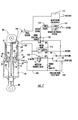
- the landing gear and auxiliary strut in accordance with the present invention preferably includes a fluid supply system 90 operable to supply fluid at appropriate pressures to the various chambers of the strut 40 in order to effect movement of the lock-up valve member 76, and also to cause retraction of the floating piston 52 for tilting the bogie beam on landing approach and to extend the strut for positioning the wheel truck in a stowage position.
- the supply system 90 includes a source 92 of relatively high-pressure fluid at a pressure P Tilt and a source 94 of relatively high-pressure fluid at a pressure P Stow , the sources 92 and 94 capable of being independently controlled to supply or shut off supply of fluid.
- the system 90 also includes a fluid return (not shown) such as a reservoir or the like, for return of fluid evacuated from the strut 40 so that the fluid can be recycled back to the fluid sources.
- the fluid sources 92, 94 are connected through respective check valves 96, 98 to a pressure-reducing valve 100 operable to output fluid at a pressure between the supply pressure of sources 92, 94 and the fluid return pressure.
- the output of the pressure-reducing valve 100 is connected to a fluid passage 102 that extends into the upper hydraulic chamber 64 of the strut.
- the P Stow source 94 is connected through a pressure-operated check valve 104 to a fluid passage 106 that extends into the floating piston control chamber 60.
- the pressure-operated check valve is also connected to the P Tilt source 92 such that when the P Tilt source 92 is pressurized and the P Stow source 94 is depressurized, the pressure-operated check valve 104 opens and fluid is evacuated from the floating piston control chamber 60, thereby causing the floating piston 52 to be retracted as shown in FIG. 2.
- Valve 104 also acts to hold the floating piston 52 extended when the landing gear is retracted into the wheel well and all landing gear actuation system pressure is set to return.
- pressure of the fluid in the upper hydraulic chamber 64 supplied from the pressure-reducing valve 100, causes the main piston 48 to stay in contact with the floating piston 52.
- the floating piston 52 causes retraction of the main piston 48, and the strut is contracted to a predetermined length.
- this length is preferably such as to place the wheel truck 28 of the landing gear in a tilted position, as shown in FIG. 1, in preparation for landing.
- This length of the strut is referred to herein as the "landing hold" position.
- the fluid supply system 90 in one embodiment includes an electrically operated solenoid valve 108 whose output is connected to the fluid passage 88 in the supply member 84.
- the solenoid valve includes a pair of inputs coupled to the P Tilt source 92 and to the fluid return.
- the solenoid valve 108 preferably is energized at takeoff so that the P Tilt pressure is directed through the fluid passage 88 to the lock-up valve 74, thereby retracting the valve member 76 so that the strut 40 locks up after a relatively short extension stroke.
- FIG. 2 depicts one embodiment in which the sensor is a proximity sensor 110 fixed in the cylinder barrel 44 and positioned to detect when the main piston 48 is compressed into the strut past the landing hold position shown in FIG. 2.
- the sensor 110 provides a signal to the solenoid valve 108 so as to cause a switch to the takeoff mode shown in FIG. 6.
- the signal from the proximity sensor 110 preferably is passed through a time-delay unit 112, which preferably is operable to provide a 5-10 second time delay before the signal is supplied to the solenoid valve 108.
- the strut 40 also includes a recycle valve 114 in the floating piston 52 between the chambers 64 and 66, which allows the floating piston 52 to return to a raised position after landing.
- a pressure relief valve 116 is also provided for relief of pressure spikes that can occur during landing and taxi when the landing gear encounter holes, bumps, or the like on the runway.
- the auxiliary strut 40 preferably provides the capability of actively extending to effect such positioning of the wheel truck. To this end, the P Tilt source 92 is depressurized and the P Stow source 94 is pressurized.
- P Stow pressure is directed into the floating piston control chamber 60, causing the floating piston to extend to the end stop 72, and the pressure from the pressure-reducing valve 100 supplied to the upper hydraulic chamber 64 causes the main piston 48 to stay in contact with the floating piston 48, so that the main piston 48 is extended to its maximum extent (referred to herein as the "stow position" of the strut).
- This causes the strut 40 to position the wheel truck 28 in a position suitable for stowage, as shown in FIG. 5.
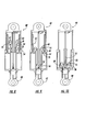
- FIG. 7 depicts an alternative preferred embodiment of a strut and control system in accordance with the invention.
- the strut 40' of FIG. 7 is similar in most respects to the strut 40 of FIGS. 2, 3, and 6, and hence the present description of the strut 40' focuses primarily on those aspects that are different from the strut 40.
- the strut 40' includes a lock-up valve member 76' having an upper snubbing seal 78' on its outer periphery. Unlike the seal 78 of the lock-up valve member 76 of the previously described strut 40, the snubbing seal 78' does not maintain continuous sealing contact with the inner surface of the tubular portion 62' of the main piston 48'.
- the snubbing seal 78' sealingly contacts the inner surface of the tubular portion 62' only when the main piston 48' is near its lock-up position with respect to the lock-up valve member 76', as further described below.
- the floating piston 52' includes a snubbing seal 53 on its inner periphery that similarly makes sealing contact with the outer surface of the tubular portion 62' only when the main piston 48' is near its lock-up position with respect to the lock-up valve member 76'.
- the tubular portion 62' of the main piston 48' includes a generally annular flange portion 63 on its upper end.
- the flange portion 63 has an inner cylindrical surface having a diameter that is smaller than that of the rest of the tubular portion 62' and is joined therewith by an inner conical surface 65 that extends downwardly and outwardly.
- the flange portion 63 has an outer cylindrical surface having a diameter that is larger than that of the rest of the tubular portion 62' and is joined with an outer conical surface 67 that extends downwardly and inwardly.
- the inner and outer cylindrical surfaces of the annular flange portion 63 are sized to make sealing contact with the snubbing seals 53 and 78'.
- the lock-up valve member 76' and the floating piston 52' are configured so that when both are fully retracted as shown in FIG. 7, the snubbing seals 53 and 78' can be simultaneously engaged by the outer and inner cylindrical surfaces of the annular flange portion 63 as shown. In this position of the strut, fluid flow between the two chambers 64 and 66 is prevented, and thus the strut is locked at a fixed length when in tension.
- the tubular portion 62' of the main piston 48' includes at least one, and preferably several, slit orifices 69 that extend through the tubular portion 62' and are oriented with their lengthwise dimensions extending lengthwise along the tubular portion 62'.
- the slit orifices 69 preferably have their upper ends spaced below the upper end of the flange portion 63 but above the outer conical surface 67, and have their lower ends below the inner conical surface 65.
- the snubbing seals 53 and 78' initially are not in contact with the tubular portion 62' of the main piston, and therefore the main piston 48' extends freely with comparatively little resistance.
- the snubbing seal 78' first comes into engagement with the inner cylindrical surface of the annular flange portion 63 (and is guided into contact therewith by the conical surface 65), such that the snubbing seal 78' begins to cover a lower portion of the slit orifices 69.
- the snubbing seal 78' progressively covers more and more of the slit orifices 69.
- the snubbing seal 53 makes sealing contact with the lower end of the cylindrical outer surface of the flange portion 63, which is just below the upper ends of the slit orifices 69.
- fluid flow through the slit orifices 69 is significantly throttled, such that further extension of the main piston 48' is substantially damped.
- the main piston extends to its full extent relative to the floating piston 52' such that the flange 70' abuts the end wall 54' of the floating piston, the slit orifices 69 become fully closed by the snubbing seals 53 and 78', and the strut 40' is locked at a fixed length as shown in FIG. 7.
- the snubbing seals 53 and 78' advantageously are formed by one or more rings of relatively stiff material that is sufficiently robust that the rings can tolerate repeated sliding over the conical surfaces 65 and 67 and over the slit orifices 69 without being cut or otherwise damaged, misshapen, or dislodged from their desired locations.
- each of the snubbing seals may be formed by a solid ring of a plastic material.
- the lock-up valve member 76' includes an elongate tubular portion 77 extending upwardly from the snubbing seal 78'.
- the lock-up valve member 76' is actuated to extend and retract by application of fluid pressure in the manner previously described in connection with the strut 40.
- the upper end of the tubular portion 77 is configured to engage a proximity switch 109 when the lock-up valve member 76' is in the retracted position as shown in FIG. 7, and the signal from the proximity switch 109 is provided to monitoring electronics 111 operable to monitor whether the strut 40' is in a takeoff mode (with the lock-up valve member 76' retracted) or a landing mode (with the lock-up valve member 76' extended).
- the switch 109 can also be used during takeoff rotation to monitor the proper function of the auxiliary strut 40'. More particularly, if the lock-up valve member 76' moves out of position by a predetermined amount during rotation when the auxiliary strut is under heavy tension load, which may be indicative of internal damage to the strut such as seal leakage, logic contained in the monitoring electronics can identify that the strut needs maintenance.
- the strut 40' is switched from one mode to the other by a signal received from an aircraft ground engagement-sensing system 113 that is operable to sense when a portion of the weight of the aircraft is supported by the landing gear.
- the signal from the ground engagement-sensing system 113 is fed through a time delay unit 112 to a solenoid valve 108 that operate as previously described in connection with the strut 40.
- the signal that initiates a mode change originates external to the strut 40' rather than within the strut.
- FIG. 9 shows the strut 40' in a landing mode ready for initial touchdown on the ground.
- the lock-up control valve 76' is fully extended and the floating piston 52' and main piston 48' are filly retracted to place the wheel truck in a tilted nose-up position, as previously described. Accordingly, when the aircraft touches down, the main piston 48' and floating piston 52' will be forcibly extended as the wheel truck is rotated toward horizontal by the upward force exerted on the aft wheels of the truck.
- the strut 40' includes a plurality of relatively large fluid passages 55 through the end wall 54' of the floating piston 52' so that the floating piston 52' and main piston 48' extend with some damping as fluid passes through the slit orifices 69.
- the extended position of the lock-up valve member 76' is such that the main piston 48' and floating piston 52' can be extended to nearly their fish extent before any significant snubbing of their movement begins. However, over the last portion of the extension of the main and floating pistons, the slit orifices 69 begin to be closed by the snubbing seal 78' so that the pistons are brought to a less abrupt halt than would otherwise be the case were no snubbing performed.
- the main strut of the landing gear becomes more and more compressed, and accordingly the strut 40' will begin to be compressed.
- the main piston 48' will separate from the floating piston 52' and be compressed upwardly into the strut. It should be noted that the passages 55 in the floating piston permit fluid flow from the upper chamber 64 to the lower chamber 66 when the main piston 48' is compressed, and thus the recycle valve 114 of the previously described strut 40 is eliminated.
- FIG. 10 shows the strut 40' in a stow position with the lock-up valve member 76', the floating piston 52', and the main piston 48' fully extended.
- the slit orifices 69 are not completely closed in this position in order to prevent a vacuum from being formed in the lower chamber, since a vacuum could interfere with subsequent retraction of the floating piston and main piston.
- FIG. 11 depicts yet another embodiment of a strut 40" that differs from the strut 40' only in that the strut 40" is a single-mode strut lacking the capability of being switched from a landing mode to a takeoff mode.
- the mode-selecting solenoid valve 108, time delay unit 112, and ground-sensing system 113 are eliminated, and the lock-up valve 76' is continuously connected to the source of P Tilt pressure.
- the lock-up valve 76' still is extended when P Tilt is depressurized and P Stow is pressurized to place the wheel truck in a stow position (as shown in FIG. 10).
- struts 40, 40', 40" have lock-up valve members that are actuated by fluid pressure to move between extended and retracted positions
- other actuator devices can alternatively be used for moving the lock-up valve member, such as a motor and ball screw arrangement.
- piston geometries including a main piston and a floating piston have been described, and the fluid path between the two fluid chambers of the strut has been illustrated as being defined in a tubular portion of the main piston, the invention is not limited to such a configuration.
- the important feature of the strut is the provision of lock-up valve structure capable of cooperating with a piston assembly to close a fluid path between two chambers of the strut at an intermediate length of the strut less than the strut's maximum length.
- Various valve and piston structures can be used to accomplish this function.
- an equivalent arrangement at least for some purposes can have the auxiliary strut attached to an aft part of the bogie beam, which would result in the bogie being tilted into a pitch-down attitude with the forward wheels down when the auxiliary strut locks up.
Landscapes
- Engineering & Computer Science (AREA)
- Mechanical Engineering (AREA)
- Aviation & Aerospace Engineering (AREA)
- Chemical & Material Sciences (AREA)
- Analytical Chemistry (AREA)
- Physics & Mathematics (AREA)
- Fluid Mechanics (AREA)
- General Engineering & Computer Science (AREA)
- Fluid-Damping Devices (AREA)
- Vehicle Body Suspensions (AREA)
- Vehicle Cleaning, Maintenance, Repair, Refitting, And Outriggers (AREA)
Applications Claiming Priority (3)
| Application Number | Priority Date | Filing Date | Title |
|---|---|---|---|
| US281457 | 1999-03-30 | ||
| US09/281,457 US6182925B1 (en) | 1999-03-30 | 1999-03-30 | Semi-levered landing gear and auxiliary strut therefor |
| EP20000201168 EP1041001B1 (fr) | 1999-03-30 | 2000-03-30 | Train d'atterrissage d'un avion comprenant un balancier, un amortisseur principal et un amortisseur auxiliaire, et un amortisseur auxiliare pour un tel train d'atterrissage |
Related Parent Applications (1)
| Application Number | Title | Priority Date | Filing Date |
|---|---|---|---|
| EP20000201168 Division EP1041001B1 (fr) | 1999-03-30 | 2000-03-30 | Train d'atterrissage d'un avion comprenant un balancier, un amortisseur principal et un amortisseur auxiliaire, et un amortisseur auxiliare pour un tel train d'atterrissage |
Publications (2)
| Publication Number | Publication Date |
|---|---|
| EP1437298A1 true EP1437298A1 (fr) | 2004-07-14 |
| EP1437298B1 EP1437298B1 (fr) | 2005-07-06 |
Family
ID=23077391
Family Applications (2)
| Application Number | Title | Priority Date | Filing Date |
|---|---|---|---|
| EP03078797A Expired - Lifetime EP1437298B1 (fr) | 1999-03-30 | 2000-03-30 | Amortisseur auxiliare pour un train d'atterrissage d'un avion comprenant un balancier, un amortisseur principal et un amortisseur auxiliaire |
| EP20000201168 Expired - Lifetime EP1041001B1 (fr) | 1999-03-30 | 2000-03-30 | Train d'atterrissage d'un avion comprenant un balancier, un amortisseur principal et un amortisseur auxiliaire, et un amortisseur auxiliare pour un tel train d'atterrissage |
Family Applications After (1)
| Application Number | Title | Priority Date | Filing Date |
|---|---|---|---|
| EP20000201168 Expired - Lifetime EP1041001B1 (fr) | 1999-03-30 | 2000-03-30 | Train d'atterrissage d'un avion comprenant un balancier, un amortisseur principal et un amortisseur auxiliaire, et un amortisseur auxiliare pour un tel train d'atterrissage |
Country Status (3)
| Country | Link |
|---|---|
| US (2) | US6182925B1 (fr) |
| EP (2) | EP1437298B1 (fr) |
| DE (2) | DE60021213T2 (fr) |
Cited By (2)
| Publication number | Priority date | Publication date | Assignee | Title |
|---|---|---|---|---|
| WO2006133902A1 (fr) * | 2005-06-14 | 2006-12-21 | Airbus Deutschland Gmbh | Procede et dispositif pour prendre en charge la rotation de decollage d’un avion |
| EP3722205A1 (fr) * | 2017-04-20 | 2020-10-14 | Safran Landing Systems UK Limited | Ensemble train d'atterrissage d'aéronef |
Families Citing this family (48)
| Publication number | Priority date | Publication date | Assignee | Title |
|---|---|---|---|---|
| US7571876B2 (en) * | 2004-01-20 | 2009-08-11 | Lord Corporation | Aircraft landing gear assembly shimmy damper |
| US7578465B2 (en) | 2004-01-20 | 2009-08-25 | Lord Corporation | Aircraft front nose landing gear and method of making an aircraft landing gear |
| EP1958873B1 (fr) * | 2004-06-18 | 2011-03-30 | Goodrich Corporation | Train d'attérrissage doté d'un système d'orientation à blocage |
| US7621481B2 (en) * | 2004-09-03 | 2009-11-24 | Lockheed-Martin Corporation | Decoupled steering/planing air vehicle nose landing gear |
| GB2428650B (en) * | 2005-08-04 | 2011-01-12 | Messier Dowty Ltd | Landing gear |
| US20070101861A1 (en) * | 2005-10-20 | 2007-05-10 | Danny Turner | Two-speed cylinder |
| US20080099602A1 (en) * | 2006-09-29 | 2008-05-01 | Zyss Michael J | System and method for detecting ground contact status of an air vehicle |
| US20080133074A1 (en) * | 2006-12-01 | 2008-06-05 | Zyss Michael J | Autonomous rollout control of air vehicle |
| GB2453554B (en) * | 2007-10-09 | 2012-03-14 | Messier Dowty Ltd | Load detection in an aircraft landing gear |
| EP2085149B2 (fr) † | 2008-01-29 | 2021-12-22 | ABI Anlagentechnik-Baumaschinen-Industriebedarf Maschinenfabrik und Vertriebsgesellschaft mbH | Vibrateur pour un appareil de fonçage vibratoire |
| FR2935680B1 (fr) * | 2008-09-08 | 2011-05-20 | Airbus | Train d'atterrissage arriere a hauteur variable |
| GB2469484B (en) * | 2009-04-15 | 2013-09-18 | Ge Aviat Systems Ltd | Landing gear actuation control system |
| US8827205B2 (en) * | 2009-05-08 | 2014-09-09 | Spectrum Aeronautical, Llc | Pneumatic blow-down actuator |
| US8448900B2 (en) * | 2010-03-24 | 2013-05-28 | The Boeing Company | Semi-levered landing gear and associated method |
| FR2959483B1 (fr) * | 2010-04-28 | 2012-06-01 | Messier Bugatti | Procede de gestion d'une liaison au sol d'un aeronef. |
| GB2483472B (en) * | 2010-09-08 | 2012-08-15 | Messier Dowty Ltd | Aircraft landing gear |
| US9481452B2 (en) | 2010-11-22 | 2016-11-01 | The Boeing Company | Hydraulic actuator for semi levered landing gear |
| US8939400B2 (en) | 2011-02-21 | 2015-01-27 | The Boeing Company | Air-ground detection system for semi-levered landing gear |
| US8998133B2 (en) | 2011-04-01 | 2015-04-07 | The Boeing Company | Landing gear system |
| EP2554474A1 (fr) * | 2011-08-05 | 2013-02-06 | EADS Construcciones Aeronauticas, S.A. | Amortisseurs de chocs |
| CA2808064C (fr) * | 2012-05-17 | 2020-02-25 | The Boeing Company | Jambe de suspension hydraulique pour train d'atterrissage partiellement manoeuvre |
| US9840322B2 (en) | 2013-05-23 | 2017-12-12 | The Boeing Company | Active semi-levered landing gear |
| DE102013010671A1 (de) * | 2013-06-26 | 2014-12-31 | Liebherr-Aerospace Lindenberg Gmbh | Sensorvorrichtung |
| US20160122008A1 (en) * | 2014-11-03 | 2016-05-05 | Borealis Technical Limited | Roller Traction Drive System for an Aircraft Drive Wheel Drive System |
| EP3135581B1 (fr) * | 2015-08-25 | 2018-03-21 | Safran Landing Systems UK Limited | Ensemble de train d'atterrissage d'avion |
| US10562614B2 (en) | 2016-09-21 | 2020-02-18 | The Boeing Company | Aircraft landing gear, aircraft, and related methods |
| US10384767B2 (en) | 2017-01-25 | 2019-08-20 | The Boeing Company | Single axle, semi-levered landing gear with shortening mechanism |
| US10597146B2 (en) | 2017-02-28 | 2020-03-24 | The Boeing Company | Aircraft landing gear having a lever assembly, aircraft including the same, and related methods |
| US10766608B2 (en) | 2017-02-28 | 2020-09-08 | The Boeing Company | Aircraft landing gear having a retract actuator, aircraft including the same, and related methods |
| US10669017B2 (en) * | 2017-02-28 | 2020-06-02 | The Boeing Company | Aircraft landing gear, aircraft, and related methods |
| US10625849B2 (en) | 2017-04-11 | 2020-04-21 | The Boeing Company | Levered landing gear with inner shock strut |
| US10801593B2 (en) | 2017-04-26 | 2020-10-13 | Paratech, Incorporated | Strut extender mechanism |
| US10800516B2 (en) | 2017-06-02 | 2020-10-13 | The Boeing Company | Semi-levered shrink landing gear |
| US10766606B2 (en) | 2017-10-17 | 2020-09-08 | Goodrich Corporation | Semi cantilevered landing gear actuated by an external articulating load damper for improved take-off |
| BR102018008986B1 (pt) * | 2017-06-23 | 2023-12-26 | Goodrich Corporation | Disposição de trem de pouso, e, método para estender uma disposição de trem de pouso para um avião |
| ES2900798T3 (es) * | 2017-11-16 | 2022-03-18 | Safran Landing Systems Uk Ltd | Actuador empujado hacia el centro |
| US11161599B2 (en) | 2018-01-26 | 2021-11-02 | The Boeing Company | Landing gear strut assembly and method therefor |
| US11008091B2 (en) | 2018-05-03 | 2021-05-18 | The Boeing Company | Body mounted shrinking landing gear |
| US10981646B2 (en) | 2018-07-30 | 2021-04-20 | The Boeing Company | Landing gear shrink link mechanism |
| CN109178297A (zh) * | 2018-08-22 | 2019-01-11 | 陈肖兰 | 一种防止坠毁的无人机用硬着陆架 |
| CN110001935B (zh) * | 2019-05-07 | 2024-05-17 | 广州中国科学院沈阳自动化研究所分所 | 一种无人机自主动平台起降辅助装置 |
| US10583919B1 (en) | 2019-07-17 | 2020-03-10 | The Boeing Company | Mechanical link with preload verification |
| US10793262B1 (en) | 2019-07-17 | 2020-10-06 | The Boeing Company | Mechanical link with preload verification |
| US11433994B2 (en) * | 2019-07-17 | 2022-09-06 | The Boeing Company | Mechanical link with preload verification |
| GB2587194A (en) * | 2019-09-13 | 2021-03-24 | Airbus Operations Ltd | Landing gear system for an aircraft |
| CN113060276B (zh) * | 2021-03-19 | 2022-08-26 | 昆山航理机载设备股份有限公司 | 飞机的起落架手柄机构 |
| GB2621161B (en) * | 2022-08-04 | 2025-01-22 | Safran Landing Systems Uk Ltd | Aircraft landing gear shock absorber strut |
| CN116424549B (zh) * | 2023-03-29 | 2025-07-15 | 西北工业大学 | 一种可停机调姿的起落架收放机构 |
Citations (5)
| Publication number | Priority date | Publication date | Assignee | Title |
|---|---|---|---|---|
| GB679060A (en) * | 1950-05-11 | 1952-09-10 | Dowty Equipment Ltd | A fluid pressure controlled strut or link of variable length |
| US2720865A (en) * | 1951-01-03 | 1955-10-18 | Electro Hydraulics Ltd | Fluid pressure operated control systems |
| US2891788A (en) * | 1954-04-15 | 1959-06-23 | Fairchild Engine & Airplane | Aircraft landing gear-double acting shock strut |
| GB2101542A (en) * | 1981-06-13 | 1983-01-19 | British Aerospace | Aircraft undercarriage unit |
| EP0492685A1 (fr) * | 1990-12-20 | 1992-07-01 | The Boeing Company | Train d'atterrissage à plusieurs axes |
Family Cites Families (17)
| Publication number | Priority date | Publication date | Assignee | Title |
|---|---|---|---|---|
| US3073586A (en) | 1959-09-03 | 1963-01-15 | Cleveland Pneumatic Ind Inc | Aircraft landing gear |
| GB1006522A (en) | 1963-10-08 | 1965-10-06 | Electro Hydraulics Ltd | Retractable undercarriages for aircraft |
| US3228305A (en) * | 1964-03-19 | 1966-01-11 | Chandler Evans Inc | Electro-pneumatic digital positioner |
| FR2270469B1 (fr) * | 1974-03-27 | 1977-03-04 | Messier Hispano Sa | |
| GB1510554A (en) | 1976-03-31 | 1978-05-10 | British Aircraft Corp Ltd | Aircraft undercarriage unit |
| US4359199A (en) | 1979-12-05 | 1982-11-16 | The United States Of America As Represented By The Secretary Of The Air Force | Soft landing gear |
| US4381857A (en) | 1980-12-08 | 1983-05-03 | Lockheed Corporation | Programmed oleo-pneumatic shock absorber |
| US4773300A (en) * | 1983-10-08 | 1988-09-27 | Wabco Westinghouse Fahrzeugbremsen Gmbh | Three-position working cylinder having dual concentric pistons |
| FR2598676B1 (fr) | 1986-05-13 | 1988-07-29 | Messier Hispano Sa | Atterrisseur d'aeronef a poutre basculante et a encombrement reduit |
| FR2616410B1 (fr) | 1987-06-09 | 1992-08-21 | Messier Hispano Sa | Dispositif d'atterrissage a poutre basculante |
| US4907492A (en) * | 1987-06-16 | 1990-03-13 | Sig Schweizerische Industrie-Gesellschaft | Apertured valve disposed in hollow piston rod of follower-type motor |
| GB8803134D0 (en) | 1988-02-11 | 1988-03-09 | British Aerospace | Aircraft undercarriage unit |
| FR2647170B1 (fr) | 1989-05-18 | 1991-08-30 | Aerospatiale | Dispositif de reduction de la souplesse d'un amortisseur oleo-pneumatique d'atterrisseur, et amortisseur et atterrisseur le comportant |
| FR2663289B1 (fr) | 1990-06-18 | 1992-09-18 | Messier Bugatti | Amortisseur d'avion. |
| FR2688467B1 (fr) | 1992-03-11 | 1994-05-13 | Messier Bugatti | Atterrisseur relevable a raccourcissement de jambe. |
| GB9223714D0 (en) | 1992-11-12 | 1992-12-23 | British Aerospace | Auxiliary control of aircraft landing gear movement |
| FR2699886B1 (fr) | 1992-12-28 | 1995-03-24 | Messier Bugatti | Atterrisseur relevable, notamment pour avion gros porteur. |
-
1999
- 1999-03-30 US US09/281,457 patent/US6182925B1/en not_active Expired - Lifetime
-
2000
- 2000-03-30 DE DE60021213T patent/DE60021213T2/de not_active Expired - Lifetime
- 2000-03-30 EP EP03078797A patent/EP1437298B1/fr not_active Expired - Lifetime
- 2000-03-30 DE DE60015216T patent/DE60015216T2/de not_active Expired - Lifetime
- 2000-03-30 EP EP20000201168 patent/EP1041001B1/fr not_active Expired - Lifetime
- 2000-11-20 US US09/716,760 patent/US6345564B1/en not_active Expired - Lifetime
Patent Citations (5)
| Publication number | Priority date | Publication date | Assignee | Title |
|---|---|---|---|---|
| GB679060A (en) * | 1950-05-11 | 1952-09-10 | Dowty Equipment Ltd | A fluid pressure controlled strut or link of variable length |
| US2720865A (en) * | 1951-01-03 | 1955-10-18 | Electro Hydraulics Ltd | Fluid pressure operated control systems |
| US2891788A (en) * | 1954-04-15 | 1959-06-23 | Fairchild Engine & Airplane | Aircraft landing gear-double acting shock strut |
| GB2101542A (en) * | 1981-06-13 | 1983-01-19 | British Aerospace | Aircraft undercarriage unit |
| EP0492685A1 (fr) * | 1990-12-20 | 1992-07-01 | The Boeing Company | Train d'atterrissage à plusieurs axes |
Cited By (6)
| Publication number | Priority date | Publication date | Assignee | Title |
|---|---|---|---|---|
| WO2006133902A1 (fr) * | 2005-06-14 | 2006-12-21 | Airbus Deutschland Gmbh | Procede et dispositif pour prendre en charge la rotation de decollage d’un avion |
| JP2008543638A (ja) * | 2005-06-14 | 2008-12-04 | エアバス・ドイチュラント・ゲーエムベーハー | 航空機の離陸引き起こしを支持する方法および装置 |
| US7963481B2 (en) | 2005-06-14 | 2011-06-21 | Airbus Deutschland Gmbh | Method and device for supporting the take-off rotation of an aircraft |
| JP4897803B2 (ja) * | 2005-06-14 | 2012-03-14 | エアバス オペレーションズ ゲーエムベーハー | 航空機の離陸引き起こしを支持する方法および装置 |
| EP3722205A1 (fr) * | 2017-04-20 | 2020-10-14 | Safran Landing Systems UK Limited | Ensemble train d'atterrissage d'aéronef |
| US11059571B2 (en) | 2017-04-20 | 2021-07-13 | Safran Landing Systems Uk Ltd | Aircraft landing gear assembly |
Also Published As
| Publication number | Publication date |
|---|---|
| US6345564B1 (en) | 2002-02-12 |
| US6182925B1 (en) | 2001-02-06 |
| DE60015216T2 (de) | 2005-10-27 |
| EP1437298B1 (fr) | 2005-07-06 |
| DE60015216D1 (de) | 2004-12-02 |
| DE60021213T2 (de) | 2006-05-24 |
| DE60021213D1 (de) | 2005-08-11 |
| EP1041001B1 (fr) | 2004-10-27 |
| EP1041001A2 (fr) | 2000-10-04 |
| EP1041001A3 (fr) | 2002-07-03 |
Similar Documents
| Publication | Publication Date | Title |
|---|---|---|
| EP1437298B1 (fr) | Amortisseur auxiliare pour un train d'atterrissage d'un avion comprenant un balancier, un amortisseur principal et un amortisseur auxiliaire | |
| US6575405B2 (en) | Control system and method for a semi-levered landing gear for an aircraft | |
| US4907760A (en) | Contracting landing gear shock strut | |
| EP2860102B1 (fr) | Système de train d'atterrissage à entretoise rétractable | |
| US8186620B2 (en) | Adjustable landing gear system | |
| US4821983A (en) | Shock absorbing jack, a stay comprising it and landing gear equipped with such a stay | |
| EP2085309B1 (fr) | Train d'atterrissage | |
| US5908174A (en) | Automatic shrink shock strut for an aircraft landing gear | |
| EP2455283B1 (fr) | Actionneur hydraulique pour train d'atterrissage d'un avion comprenant un balancier, un amortisseur principal et un amortisseur auxiliaire | |
| US4720063A (en) | Main landing gear with variable length drag brace | |
| US8556209B2 (en) | Electric-powered transfer cylinder for landing gear system | |
| US4291850A (en) | Contractable shock absorber strut | |
| EP3263449B1 (fr) | Train d'atterrissage d'avion | |
| US8070095B2 (en) | Shrinking shock strut system for retractable landing gear | |
| US8684306B2 (en) | Steering collar locking mechanism for retractable aircraft nose landing gear | |
| US3533613A (en) | Axially retractable landing gear | |
| EP3135582B1 (fr) | Mécanisme de patin de queue pour aéronef à trois positions et procédé d'actionnement | |
| US2735634A (en) | fosness | |
| JPS63279998A (ja) | 航空機用ローリング装置 | |
| US4651955A (en) | Device for automatically controllable unloading of aircraft wings | |
| EP4003833B1 (fr) | Positionneur de poutre de camion à roues multiples d'aéronef | |
| EP3508420B1 (fr) | Systèmes hydrauliques permettant de rétracter des trains d'atterrissage | |
| US3027122A (en) | Aircraft landing gear |
Legal Events
| Date | Code | Title | Description |
|---|---|---|---|
| PUAI | Public reference made under article 153(3) epc to a published international application that has entered the european phase |
Free format text: ORIGINAL CODE: 0009012 |
|
| AC | Divisional application: reference to earlier application |
Ref document number: 1041001 Country of ref document: EP Kind code of ref document: P |
|
| AK | Designated contracting states |
Kind code of ref document: A1 Designated state(s): AT BE CH CY DE DK ES FI FR GB GR IE IT LI LU MC NL PT SE |
|
| GRAP | Despatch of communication of intention to grant a patent |
Free format text: ORIGINAL CODE: EPIDOSNIGR1 |
|
| 17P | Request for examination filed |
Effective date: 20041118 |
|
| AKX | Designation fees paid |
Designated state(s): DE FR GB |
|
| GRAS | Grant fee paid |
Free format text: ORIGINAL CODE: EPIDOSNIGR3 |
|
| GRAA | (expected) grant |
Free format text: ORIGINAL CODE: 0009210 |
|
| AC | Divisional application: reference to earlier application |
Ref document number: 1041001 Country of ref document: EP Kind code of ref document: P |
|
| AK | Designated contracting states |
Kind code of ref document: B1 Designated state(s): DE FR GB |
|
| REG | Reference to a national code |
Ref country code: GB Ref legal event code: FG4D |
|
| REF | Corresponds to: |
Ref document number: 60021213 Country of ref document: DE Date of ref document: 20050811 Kind code of ref document: P |
|
| ET | Fr: translation filed | ||
| PLBE | No opposition filed within time limit |
Free format text: ORIGINAL CODE: 0009261 |
|
| STAA | Information on the status of an ep patent application or granted ep patent |
Free format text: STATUS: NO OPPOSITION FILED WITHIN TIME LIMIT |
|
| 26N | No opposition filed |
Effective date: 20060407 |
|
| REG | Reference to a national code |
Ref country code: FR Ref legal event code: PLFP Year of fee payment: 17 |
|
| REG | Reference to a national code |
Ref country code: FR Ref legal event code: PLFP Year of fee payment: 18 |
|
| REG | Reference to a national code |
Ref country code: FR Ref legal event code: PLFP Year of fee payment: 19 |
|
| PGFP | Annual fee paid to national office [announced via postgrant information from national office to epo] |
Ref country code: FR Payment date: 20190325 Year of fee payment: 20 Ref country code: DE Payment date: 20190327 Year of fee payment: 20 |
|
| PGFP | Annual fee paid to national office [announced via postgrant information from national office to epo] |
Ref country code: GB Payment date: 20190404 Year of fee payment: 20 |
|
| REG | Reference to a national code |
Ref country code: DE Ref legal event code: R071 Ref document number: 60021213 Country of ref document: DE |
|
| REG | Reference to a national code |
Ref country code: GB Ref legal event code: PE20 Expiry date: 20200329 |
|
| PG25 | Lapsed in a contracting state [announced via postgrant information from national office to epo] |
Ref country code: GB Free format text: LAPSE BECAUSE OF EXPIRATION OF PROTECTION Effective date: 20200329 |