EP1437314B1 - Verfahren und Vorrichtung zur automatischen Palletisierung von Gegenständen - Google Patents
Verfahren und Vorrichtung zur automatischen Palletisierung von Gegenständen Download PDFInfo
- Publication number
- EP1437314B1 EP1437314B1 EP03000260A EP03000260A EP1437314B1 EP 1437314 B1 EP1437314 B1 EP 1437314B1 EP 03000260 A EP03000260 A EP 03000260A EP 03000260 A EP03000260 A EP 03000260A EP 1437314 B1 EP1437314 B1 EP 1437314B1
- Authority
- EP
- European Patent Office
- Prior art keywords
- objects
- gripping
- elongated element
- segments
- conveyor
- Prior art date
- Legal status (The legal status is an assumption and is not a legal conclusion. Google has not performed a legal analysis and makes no representation as to the accuracy of the status listed.)
- Expired - Lifetime
Links
Images




Classifications
-
- B—PERFORMING OPERATIONS; TRANSPORTING
- B65—CONVEYING; PACKING; STORING; HANDLING THIN OR FILAMENTARY MATERIAL
- B65G—TRANSPORT OR STORAGE DEVICES, e.g. CONVEYORS FOR LOADING OR TIPPING, SHOP CONVEYOR SYSTEMS OR PNEUMATIC TUBE CONVEYORS
- B65G57/00—Stacking of articles
- B65G57/02—Stacking of articles by adding to the top of the stack
- B65G57/16—Stacking of articles of particular shape
- B65G57/20—Stacking of articles of particular shape three-dimensional [3D], e.g. cubiform or cylindrical
- B65G57/22—Stacking of articles of particular shape three-dimensional [3D], e.g. cubiform or cylindrical in layers each of predetermined arrangement
-
- B—PERFORMING OPERATIONS; TRANSPORTING
- B65—CONVEYING; PACKING; STORING; HANDLING THIN OR FILAMENTARY MATERIAL
- B65G—TRANSPORT OR STORAGE DEVICES, e.g. CONVEYORS FOR LOADING OR TIPPING, SHOP CONVEYOR SYSTEMS OR PNEUMATIC TUBE CONVEYORS
- B65G47/00—Article or material-handling devices associated with conveyors; Methods employing such devices
- B65G47/74—Feeding, transfer, or discharging devices of particular kinds or types
- B65G47/90—Devices for picking-up and depositing articles or materials
-
- B—PERFORMING OPERATIONS; TRANSPORTING
- B65—CONVEYING; PACKING; STORING; HANDLING THIN OR FILAMENTARY MATERIAL
- B65G—TRANSPORT OR STORAGE DEVICES, e.g. CONVEYORS FOR LOADING OR TIPPING, SHOP CONVEYOR SYSTEMS OR PNEUMATIC TUBE CONVEYORS
- B65G57/00—Stacking of articles
- B65G57/32—Stacking of articles characterised by stacking during transit
Definitions
- the present invention relates to a method for operating and controlling the gripping hands of an automatic apparatus suitable for gripping, displacing and delivering objects.
- the invention relates to an apparatus for palletising objects coming from an automatic production line.
- Palletization systems in particular, are often equipped with robots having a wrist with several degrees of freedom.
- To the wrist at least one gripping device is connected with clamps or "hands" for automatically positioning the objects by putting them adjacent to each other and in many layers.
- the robots used for palletization of objects that come from automatic production lines are usually located in a palletization area and can also assist at the same time several conveyors.
- the robots which are usually anthropomorphic, Cartesian or polar, work at a palletization speed according to the carrying capacity of the wrist, to the trajectories and to any additional actions to perform. Therefore, to improve the speed the hands of the robot must be light, so that the objects to manipulate are the main part of the load on the wrist.
- the gripping hands furthermore, must grip and release the object with precision and quickly.
- the usually flat hands have fixed opening/closing stroke independently from the size of the object to load; in particular, if the size range of the objects to manipulate varies much, for example for palletization of objects of different shape, when handling the objects of minimum size the hands must open like for objects of maximum size, thus effecting a long idle portion of the stroke before gripping the object.
- L-shaped gripping hands exist that are positioned with a portion under the package, thus supporting it.
- the existing apparatus do not allow to handle collapsible packages, for example sacks of pasta, of flour or of other bulk products, which while carried can change their shape, thus loosening the grip on the sack and causing it to be released.
- NL9101951 describes an apparatus for palletizing and stacking sacks that has a gripping device that approaches laterally the sacks with an elongated element having a first portion and a second portion. The second portion moves then under the sack by means of a relative rotation between the first and the second portion.
- This apparatus has a stiff second portion.
- DE3817013 also describes a method conform to the preamble of claim 1 and an apparatus conform to the preamble of claim 9, for palletizing and stacking sacks that has a gripping device with a plurality of segments or "phalanxes" in a row, capable of fitting and adapting to the size and the shape of the sacks.
- the segments or "phalanxes” are free from one another and are rotated with respect to each other by pulling a tendon that also bears all the load.
- the relative rotation between said first and said second portion is obtained by a plurality of relative rotations of a plurality of segments or "phalanxes" in a row.
- the means for actuating the rotation of the first and the second portion comprise preferably a tendon, connected to a predetermined segment of the elongated element for causing the mutual rotation of said segments or phalanxes about the respective hinges, pulled by an actuator at the other end, the tendon extending eccentrically to the hinges that connect in turn the phalanxes.
- Transferring the object to a palletization area comprises preferably releasing said or each object by the following steps:
- the steps of picking up and transferring are repeated in turn on a plurality or groups of objects up to loading completely the pallet.
- a centring step is provided of said or each gripping hand with respect to said object. This way it is possible to provide a steadier grip of the object and therefore to operate with high transferring speed.
- said overlapping is obtained by a combination of a reciprocation of a plane of a conveyor and the feeding movement of another conveyor partially overlapped with respect to said plane.
- This combination of movements can be assisted by sensors of presence, for example optical sensors, associated to means for moving said objects on said conveyors to obtain the overlapping condition.
- a preliminary step can be provided of lifting said or each object by the plane of the conveyor, by means of a support movable orthogonally through the conveyor.
- the transfer of sacks of product at the palletization area by the gripping hands can provide the following steps:
- the delivery of at least one sack put "oriented vertically” can occur by a relative rotation of the first and of the second portion of said or each elongated element only at a side of the sack, in order to leave it to fall laterally thus withdrawing its support action, said rotation causing in turn a rotation of said sack about the end of the second portion of said or each elongated element arranged at the other side of the sack and then its orientation in vertical allowing to fall "oriented vertically” between said first and said second stack of sacks already present on said pallet.
- the means for actuating the rotation of the first and the second portion comprise a tendon, connected to a predetermined segment of the elongated element for causing the mutual rotation of said segments or phalanxes about the respective hinges, pulled by an actuator at the other end, the tendon extending eccentrically to the hinges that connect in turn the phalanxes.
- sacks 5 are arranged to form stacks 6 (figure 5) in order to increase the speed of the palletization process.
- first conveyor 10 This occurs by a combination of relative movements between a first conveyor 10 and a second conveyor 20 partially overlapping the first.
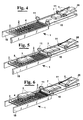
- a first row of sacks 5 coming from the production line is arranged by second conveyor 20 onto first conveyor 10 (figure 3).
- a second row of sacks 5 is then put on the first row of sacks 5.
- Stacks 7 of sacks 5 thus formed are transferred from the plane 10 onto a conveyor 1 comprising, for example, dragging rollers 2 separated by apertures 3.
- Conveyor 1 transfers stacks 7 to a gripping area defined diagrammatically in figure by a dotted line 8 (figure 5).
- a support 4 is present, for example forming a cradle, having a plurality of elements that can translate orthogonally to the plane of conveyor 1 through apertures 3, from a first position, where they are arranged under conveyor 1 same (figure 4), and a position where they cross the plane of conveyor 1 raising from it stacks 7 of sacks 5 (figure 6).
- Such step facilitates the next picking up step of stacks 7 by gripping hands 25a-25d, as described hereafter.
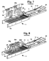
- gripping hands 25a-25d have elongated ends 26, which by means of a combination of movements of the respective gripping hands are arranged between a starting position, where they are external to cradle support 4 (figure 7), and a position where they cross the cradle 4 same at the spaces set between the many parts thereof (figure 8).
- Translating the gripping hands is carried out by a robotized head, for example that described in European Patent Application EP 1293307 A2, in the name of the same applicant, actuated by a screw or a belt on a respective guide and driven by step motors.
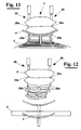
- a portion 26b of elongated elements 26 rotates with respect to portion 26a and moves under the stacks 7.
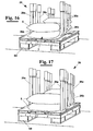
- gripping hands 25a-25d raise and move sacks 5, which are supported by portions 26b of elongated elements 26, away from conveyor 1 (figure 10 and 12) for then delivering them at a palletization area where pallets 60 are preliminarily arranged (figure 16 and 17).
- each elongated element 26 comprises a plurality of segments or "phalanxes" 27 interconnected at an end 27a by means of hinges 28, about which segments 27 can rotate biased by springs 29.
- segments 27 can rotate between a first position, where they are aligned (figure 14), and a second position, where the end 27b without hinges of two successive segments 27 are rotated (figure 15).
- the sum of the single relative rotations of segments 27 produces, then, a rotation between the first portion 26a and the second portion 26b of elongated element 26.
- a predetermined segment 27' of elongated element 26 is connected to an end of a tendon 40.
- the tendon passes through all the segments preceding segment 27', along a line different from the line formed by hinges 28.
- segment 27' to which the tendon is connected starts to rotate about its hinge 28', biased by spring 29'.
- segments 27 arranged downstream of segment 27' do not rotate about the respective hinges 28, but rotate as a stiff body, by means of abutments that prevent them to rotate back.
- segment 27' to which tendon 40 is connected divides elongated element 26 into two portions 26a and 26b that as above described are capable of rotating with respect to each other.
- a single actuator 50 can operate all the elongated elements 26 of a gripping hand 25.
- the cables 40 coming from elongated elements 26 of a same gripping hand 25 are connected to a cylinder or "drum” 41 capable of rotating about its own axis. It is brought into rotation by actuator 50 through a rod 42 operatively connected to the stem 51 of actuator 50 same.
Landscapes
- Engineering & Computer Science (AREA)
- Mechanical Engineering (AREA)
- Specific Conveyance Elements (AREA)
- Stacking Of Articles And Auxiliary Devices (AREA)
- Warehouses Or Storage Devices (AREA)
Claims (10)
- Verfahren zum Betrieb und zur Steuerung der Greiferhände (25a-25d) einer automatischen Vorrichtung, geeignet zum Greifen, Versetzen und Ablegen von Objekten, wie zum Beispiel von Produkten in Säcken (5), beschickt von einer automatischen Produktionslinie, umfassend die Schritte:- Einführen auf einem Förderband (1) wenigstens eines Objekts (5) in eine Greiferstation;- Positionieren in der Station wenigstens einer Greiferhand, umfassend wenigstens ein verlängertes Element (26) an dem oder jedem Objekt (5);- Aufnehmen des oder jedes Objekts (5) durch die oder jede Greiferhand und Transportieren des Objekts zu einem Palettierbereich;wobei der Schritt des Aufnehmens ausgeführt wird mit einer relativen Bewegung zwischen dem Objekt (5) und der Greiferhand, durch seitliches Annähern eines ersten Abschnitts (26a) des oder jedes verlängerten Elements (26) an das Objekt (5) und durch Positionieren eines zweiten Abschnitts (26b) des oder jedes verlängerten Elements (26) unter dem Objekt (5) mittels einer relativen Drehung zwischen dem ersten (26a) und dem zweiten Abschnitt (26b),
und wobei die relative Drehung zwischen dem ersten (26a) und dem zweiten Abschnitt (26b) erreicht wird durch mehrere relative Drehungen mehrerer aufeinander folgender Segmente (27, 27') oder "Fingerglieder", dadurch gekennzeichnet, dass
die Segmente (27, 27') oder "Fingerglieder" an einem Ende miteinander mittels Gelenke (28) verbunden sind, um die die Segmente (27, 27') bezogen aufeinander drehbar sind, vorgespannt mit Federn (29), zwischen einer ersten Position, in der zwei aufeinander folgende Segmente (27, 27') ausgerichtet sind, und einer zweiten Position, in der jedes der aufeinander folgenden Segmente (27, 27'), jeweils bezogen auf das Element davor, gedreht ist. - Verfahren nach Anspruch 1, wobei das Mittel zur Betätigung der Drehung des ersten und des zweiten Abschnitts (26b) eine Sehne (40) umfasst, an einem Ende verbunden mit einem vorherbestimmten Segment (27, 27') des verlängerten Elements (26) zum Auslösen der wechselseitigen Drehung der Segmente (27, 27') oder "Fingerglieder" um die jeweiligen Gelenke (28) durch Ziehen des anderen Endes durch ein Betätigungsorgan, wobei die Sehne (40) exzentrisch verläuft zu den Gelenken (28), die wiederum die "Fingerglieder" verbinden.
- Verfahren nach Anspruch 1, wobei das Transportieren zu einem Palettierbereich das Ablegen des oder jedes Objekts (5) umfasst, durch die Schritte:- Niederlassen der Greiferhand bis das oder jedes verlängerte Element (26) an seinem unteren Abschnitt die Palette oder ein Objekt (5) berührt, das sich darunter befindet und zuvor auf die Palette gebracht worden ist;- Lösen des zweiten Abschnitts (26b) des oder jedes verlängerten Elements (26) bezogen auf den ersten Abschnitt (26a) :- Hochheben der Greiferhand, wobei das oder jedes verlängerte Element (26) bezogen auf das Objekt (5) seitlich gleitet und das Objekt auf der Palette oder auf dem darunter befindlichen Objekt (5) zurücklässt.
- Verfahren nach Anspruch 1, wobei, vor dem Schritt des Einführens, von der Greiferstation bandaufwärts, die folgenden Schritte vorgesehen sind:- Vorbereiten eines ersten Objekts (5) in einer Ebene des Förderbandes (1);- Auflegen wenigstens eines weiteren Objekts (5) auf das erste Objekt (5) als Aufbau wenigstens eines Stoßes (7) von Objekten;- Hochheben und Transportieren von dem Förderband (1) des oder jedes Stoßes (7) von Objekten.
- Verfahren nach Anspruch 4, wobei das Aufliegen erreicht wird durch eine Kombination einer Hin- und Herbewegung der Ebene des Förderbandes (1) und der Einführbewegung eines anderen Förderbandes (1), der bezogen auf die Ebene, teilweise darüber liegt.
- Verfahren nach Anspruch 1, wobei zur Erleichterung des Schrittes des Aufnehmens des oder jedes Objekts (5) ein vorausgehender Schritt des Hochhebens des oder jedes Objekts (5) von der Ebene des Förderbandes (1) mittels einer orthogonal durch das Förderband (1) beweglichen Unterstützung vorgesehen ist.
- Verfahren nach Anspruch 1, wobei das Transportieren der Objekte (5) im Palettierbereich durch die Greiferhände (25a-25d) die folgenden Schritte vorsieht:- Ablegen wenigstens eines ersten Stoßes (7) von Objekten (5) auf einer in dem Palettierbereich vorbereiteten Palette;- Ablegen wenigstens eines zweiten Stoßes (7) von Objekten (5) auf der Palette in einem Abstand von dem ersten Stoß (7) von Objekten (5);- Ablegen wenigstens eines Objekts, das "vertikal orientiert" zwischen den ersten und den zweiten Stoß (7) von Objekten (5) gebracht wird.
- Verfahren nach Anspruch 7, wobei wenigstens ein Objekt in "vertikal orientierte" Position gebracht wird durch Drehung des ersten Abschnitts (26a) relativ zu dem zweiten Abschnitt (26b) des oder jedes verlängerten Elements (26) an nur einer Seite des Objekts, um es seitlich fallen zu lassen, wobei die Stützwirkung aufgehoben wird, wobei die Drehung wiederum eine Drehung des Objekts um das Ende des zweiten Abschnitts (26b) des oder jedes verlängerten Elements (26) auslöst, das auf der anderen Seite des Objekts angeordnet ist und so durch seine Orientierung ermöglicht, dass das Objekt "vertikal orientiert" zwischen den ersten und den zweiten Stoß (7) von Objekten (5) fällt, die bereits auf der Palette vorhanden sind.
- Vorrichtung zum Palettieren von Objekten, die aus einer automatischen Produktionslinie kommen, wie zum Beispiel Produkte in Säcken (5), umfassend wenigstens eine Greiferhand, die geeignet ist zum Greifen, Versetzen und Ablegen von Objekten, die wenigstens ein verlängertes Element (26) hat, mit einem ersten Abschnitt (26a), der sich dem Objekt (5) seitlich nähert, und einem zweiten Abschnitt (26b), der unter das Objekt (5) positioniert wird mittels einer relativen Drehung zwischen dem ersten (26a) und dem zweiten Abschnitt (26b),wobei wenigstens eine erste und wenigstens eine zweite Greiferhand vorgesehen sind, an gegenüberliegenden Seiten angeordnet bezogen auf das oder jedes Objekt, die sich aufeinander zu /voneinander weg bewegen können und in parallele Richtung, wobei die relative Drehung zwischen dem ersten (26a) und dem zweiten Abschnitt (26b) von einem Betätigungsorgan ausgeführt wird und vorgespannt ist mit Federn (29), wobei, wenn die Betätigungsorgane gelöst sind, jedes verlängerte Element (26) zu gerader Ausrichtung tendiert, und wobei jedes verlängerte Element (26) wenigstens in einem Abschnitt des Elements mehrere Segmente (27, 27') oder "Fingerglieder" umfasst, die aufeinander bezogen drehbar sind, um die relative Drehung zu erreichen, zwischen dem ersten (26a) und dem zweiten Abschnitt (26b), dadurch gekennzeichnet, dass die Segmente (27, 27') oder "Fingerglieder" an einem Ende miteinander mittels Gelenke (28) verbunden sind, um welche die Segmente (27, 27') bezogen aufeinander drehbar sind, vorgespannt mit Federn (29), zwischen einer ersten Position, in der zwei aufeinander folgende Segmente (27, 27') ausgerichtet sind, und einer zweiten Position, in der jedes der aufeinander folgenden Segmente (27, 27'), jeweils bezogen auf das Element davor, gedreht ist.
- Vorrichtung nach Anspruch 9, wobei das Mittel zur Betätigung der Drehung des ersten und des zweiten Abschnitts (26b) eine Sehne (40) umfasst, an einem Ende verbunden mit einem vorherbestimmten Segment (27, 27') des verlängerten Elements (26b) zum Auslösen der wechselseitigen Drehung der Segmente (27, 27') oder "Fingerglieder" um die jeweiligen Gelenke (28) durch Ziehen des anderen Endes durch ein Betätigungsorgan, wobei die Sehne (40) exzentrisch verläuft zu den Gelenken (28), die ihrerseits die "Fingerglieder" (27, 27') verbinden.
Priority Applications (4)
| Application Number | Priority Date | Filing Date | Title |
|---|---|---|---|
| ES03000260T ES2286336T3 (es) | 2003-01-08 | 2003-01-08 | Metodo y aparato para paletizacion automatica de objetos. |
| EP03000260A EP1437314B1 (de) | 2003-01-08 | 2003-01-08 | Verfahren und Vorrichtung zur automatischen Palletisierung von Gegenständen |
| AT03000260T ATE357390T1 (de) | 2003-01-08 | 2003-01-08 | Verfahren und vorrichtung zur automatischen palletisierung von gegenständen |
| DE60312633T DE60312633D1 (de) | 2003-01-08 | 2003-01-08 | Verfahren und Vorrichtung zur automatischen Palletisierung von Gegenständen |
Applications Claiming Priority (1)
| Application Number | Priority Date | Filing Date | Title |
|---|---|---|---|
| EP03000260A EP1437314B1 (de) | 2003-01-08 | 2003-01-08 | Verfahren und Vorrichtung zur automatischen Palletisierung von Gegenständen |
Publications (2)
| Publication Number | Publication Date |
|---|---|
| EP1437314A1 EP1437314A1 (de) | 2004-07-14 |
| EP1437314B1 true EP1437314B1 (de) | 2007-03-21 |
Family
ID=32479887
Family Applications (1)
| Application Number | Title | Priority Date | Filing Date |
|---|---|---|---|
| EP03000260A Expired - Lifetime EP1437314B1 (de) | 2003-01-08 | 2003-01-08 | Verfahren und Vorrichtung zur automatischen Palletisierung von Gegenständen |
Country Status (4)
| Country | Link |
|---|---|
| EP (1) | EP1437314B1 (de) |
| AT (1) | ATE357390T1 (de) |
| DE (1) | DE60312633D1 (de) |
| ES (1) | ES2286336T3 (de) |
Families Citing this family (11)
| Publication number | Priority date | Publication date | Assignee | Title |
|---|---|---|---|---|
| KR100591787B1 (ko) * | 2004-12-16 | 2006-06-26 | 전재형 | 자동 판재 적재 및 배출장치 |
| ITPI20060141A1 (it) * | 2006-12-01 | 2008-06-02 | Morelli S R L | Dispositivo trasportatore automatico per l'alimentazione di articoli verso una stazione di prelievo |
| ES2563806T3 (es) * | 2011-11-02 | 2016-03-16 | Langhammer Gmbh | Dispositivo para el transporte y la manipulación de productos |
| ITPR20120007A1 (it) * | 2012-02-17 | 2013-08-18 | Gea Procomac Spa | Dispositivo e metodo per impilare strati di pacchi |
| DE202016003209U1 (de) | 2016-05-19 | 2016-07-27 | Holmatec Maschinenbau GmbH & Co. KG | Vorrichtung zur Aufnahme und Abgabe von Stückgut |
| US10556338B1 (en) * | 2017-07-31 | 2020-02-11 | Amazon Technologies, Inc. | Compliant finger tip for item manipulation |
| CN110626806B (zh) * | 2019-09-21 | 2021-07-02 | 东莞市永润港口机械工程有限公司 | 一种用于货物的自动化吊装搬运设备的工作方法 |
| CN110589397B (zh) * | 2019-09-21 | 2021-06-25 | 江苏欧超重工科技有限公司 | 一种用于货物的自动化吊装搬运设备 |
| CN113602822A (zh) * | 2021-08-18 | 2021-11-05 | 安徽思达智能装备有限公司 | 一种适用于生产车间的工业机器人 |
| CN114751191B (zh) * | 2022-04-08 | 2023-06-09 | 浙江集秀元智能装备有限公司 | 一种用于电池极板的多工位移料装置 |
| CN116372947A (zh) * | 2023-03-14 | 2023-07-04 | 中国一冶集团有限公司 | 基于三维点云的机器人自动拆袋方法及系统 |
Family Cites Families (12)
| Publication number | Priority date | Publication date | Assignee | Title |
|---|---|---|---|---|
| US1693074A (en) * | 1926-12-24 | 1928-11-27 | Falco Michael | Lifting device |
| DE1756152A1 (de) * | 1968-04-11 | 1970-03-12 | Bason & Sons Ltd | Aufnahmevorrichtung |
| JPS58139926A (ja) * | 1982-02-10 | 1983-08-19 | Hitomi Matsuba | 積上げ装置 |
| DE3540121A1 (de) * | 1985-11-13 | 1987-05-14 | Moellers Maschf Gmbh | Vorrichtung zum ergreifen und absetzen von stueckguetern |
| DE3817013A1 (de) * | 1988-05-09 | 1989-11-23 | Behn Maschf | Vorrichtung zum ergreifen, transportieren und palettieren eines gefuellten sackes |
| US5066189A (en) * | 1990-08-03 | 1991-11-19 | Shell Material Handling Systems, Inc. | Method and apparatus for handling discrete cargo units |
| DE4033587A1 (de) * | 1990-10-22 | 1992-04-23 | Focke & Co | Vorrichtung zum handhaben von gegenstaenden, wie kartons |
| NL9101951A (nl) * | 1991-11-21 | 1993-06-16 | Jan Cornelis Kremer | Inrichting voor het op pallets stapelen van voorwerpen, in het bijzonder zakken of balen met bulkgoed. |
| JPH05305927A (ja) * | 1991-12-20 | 1993-11-19 | Nippon Cement Co Ltd | シート状部材の重ね合わせ器および該重ね合わせ器を使用した重量検査装置 |
| NL9201292A (nl) * | 1992-07-17 | 1994-02-16 | Food Processing Systems | Werkwijze en inrichting voor het vullen van omdozen, kratten of display-containers met in hoofdzaak blokvormige voorwerpen en een lifttafel voor gebruik bij de werkwijze. |
| JPH0881056A (ja) * | 1994-09-14 | 1996-03-26 | Utsunomiya Seiki Kk | パレタイザー |
| US5630695A (en) * | 1995-09-14 | 1997-05-20 | Flomat Pty Ltd | Pallet sorting machine |
-
2003
- 2003-01-08 ES ES03000260T patent/ES2286336T3/es not_active Expired - Lifetime
- 2003-01-08 DE DE60312633T patent/DE60312633D1/de not_active Expired - Lifetime
- 2003-01-08 AT AT03000260T patent/ATE357390T1/de not_active IP Right Cessation
- 2003-01-08 EP EP03000260A patent/EP1437314B1/de not_active Expired - Lifetime
Also Published As
| Publication number | Publication date |
|---|---|
| DE60312633D1 (de) | 2007-05-03 |
| EP1437314A1 (de) | 2004-07-14 |
| ES2286336T3 (es) | 2007-12-01 |
| ATE357390T1 (de) | 2007-04-15 |
Similar Documents
| Publication | Publication Date | Title |
|---|---|---|
| JP7533979B2 (ja) | パレタイザシステム及びデパレ・パレタイジング方法 | |
| EP1293307A2 (de) | Verfahren und Vorrichtung zum Betrieb der Spannvorrichtung von automatischen Manipulatoren | |
| US6082080A (en) | Device for mechanically grasping and palletizing rectangular objects | |
| US9701490B2 (en) | Method and tool for palletizing mixed load products | |
| CN107878854B (zh) | 机器人装箱集成系统的控制方法 | |
| US10086510B1 (en) | Dual robotic case packing system for standup product | |
| CN109562897B (zh) | 用于处理成件货物的操作系统和方法 | |
| US11383865B2 (en) | Food conveyor and packaging systems and methods | |
| CN207433977U (zh) | 机器人装箱集成系统 | |
| JPH04354725A (ja) | パッケージを積重体に形成する機械 | |
| CN107810155A (zh) | 用于装载存储区域的装置和方法 | |
| EP1437314A1 (de) | Verfahren und Vorrichtung zur automatischen Palletisierung von Gegenständen | |
| JP7462291B2 (ja) | 物品群供給装置及び物品群供給方法 | |
| CN109415175B (zh) | 一种智能上下料系统及其工作方法 | |
| JPH09131685A (ja) | ロボットのハンド装置 | |
| CN111094155A (zh) | 用于处理以至少一排依次运动的件货的方法和设备 | |
| US6422375B1 (en) | System and method for transporting and reorienting items | |
| US12428181B2 (en) | System and method for handling packaging units, and manipulator unit | |
| JP2710016B2 (ja) | 方形の積体をロボットにより自動パレタイジングする方法 | |
| CN112645067A (zh) | 码垛系统及方法 | |
| EP4644279A2 (de) | Greifer für eine handhabungsvorrichtung | |
| EP3401249A1 (de) | Palettierungsvorrichtung | |
| CN220764856U (zh) | 用于二级包装的分组器和用于操纵和码垛二级包装的系统 | |
| JPH09328227A (ja) | 板状体段積み装置 | |
| EP3323736B2 (de) | Verfahren zum betreiben eines palettierers |
Legal Events
| Date | Code | Title | Description |
|---|---|---|---|
| PUAI | Public reference made under article 153(3) epc to a published international application that has entered the european phase |
Free format text: ORIGINAL CODE: 0009012 |
|
| AK | Designated contracting states |
Kind code of ref document: A1 Designated state(s): AT BE BG CH CY CZ DE DK EE ES FI FR GB GR HU IE IT LI LU MC NL PT SE SI SK TR |
|
| AX | Request for extension of the european patent |
Extension state: AL LT LV MK RO |
|
| 17P | Request for examination filed |
Effective date: 20050110 |
|
| AKX | Designation fees paid |
Designated state(s): AT BE BG CH CY CZ DE DK EE ES FI FR GB GR HU IE IT LI LU MC NL PT SE SI SK TR |
|
| GRAP | Despatch of communication of intention to grant a patent |
Free format text: ORIGINAL CODE: EPIDOSNIGR1 |
|
| RTI1 | Title (correction) |
Free format text: METHOD AND APPARATUS FOR THE AUTOMATIC PALLETIZATION OF OBJECTS |
|
| GRAS | Grant fee paid |
Free format text: ORIGINAL CODE: EPIDOSNIGR3 |
|
| GRAA | (expected) grant |
Free format text: ORIGINAL CODE: 0009210 |
|
| AK | Designated contracting states |
Kind code of ref document: B1 Designated state(s): AT BE BG CH CY CZ DE DK EE ES FI FR GB GR HU IE IT LI LU MC NL PT SE SI SK TR |
|
| PG25 | Lapsed in a contracting state [announced via postgrant information from national office to epo] |
Ref country code: SI Free format text: LAPSE BECAUSE OF FAILURE TO SUBMIT A TRANSLATION OF THE DESCRIPTION OR TO PAY THE FEE WITHIN THE PRESCRIBED TIME-LIMIT Effective date: 20070321 Ref country code: CH Free format text: LAPSE BECAUSE OF FAILURE TO SUBMIT A TRANSLATION OF THE DESCRIPTION OR TO PAY THE FEE WITHIN THE PRESCRIBED TIME-LIMIT Effective date: 20070321 Ref country code: FI Free format text: LAPSE BECAUSE OF FAILURE TO SUBMIT A TRANSLATION OF THE DESCRIPTION OR TO PAY THE FEE WITHIN THE PRESCRIBED TIME-LIMIT Effective date: 20070321 Ref country code: BE Free format text: LAPSE BECAUSE OF FAILURE TO SUBMIT A TRANSLATION OF THE DESCRIPTION OR TO PAY THE FEE WITHIN THE PRESCRIBED TIME-LIMIT Effective date: 20070321 Ref country code: LI Free format text: LAPSE BECAUSE OF FAILURE TO SUBMIT A TRANSLATION OF THE DESCRIPTION OR TO PAY THE FEE WITHIN THE PRESCRIBED TIME-LIMIT Effective date: 20070321 Ref country code: NL Free format text: LAPSE BECAUSE OF FAILURE TO SUBMIT A TRANSLATION OF THE DESCRIPTION OR TO PAY THE FEE WITHIN THE PRESCRIBED TIME-LIMIT Effective date: 20070321 Ref country code: AT Free format text: LAPSE BECAUSE OF FAILURE TO SUBMIT A TRANSLATION OF THE DESCRIPTION OR TO PAY THE FEE WITHIN THE PRESCRIBED TIME-LIMIT Effective date: 20070321 |
|
| REG | Reference to a national code |
Ref country code: GB Ref legal event code: FG4D |
|
| REG | Reference to a national code |
Ref country code: CH Ref legal event code: EP |
|
| REF | Corresponds to: |
Ref document number: 60312633 Country of ref document: DE Date of ref document: 20070503 Kind code of ref document: P |
|
| REG | Reference to a national code |
Ref country code: IE Ref legal event code: FG4D |
|
| PG25 | Lapsed in a contracting state [announced via postgrant information from national office to epo] |
Ref country code: SE Free format text: LAPSE BECAUSE OF FAILURE TO SUBMIT A TRANSLATION OF THE DESCRIPTION OR TO PAY THE FEE WITHIN THE PRESCRIBED TIME-LIMIT Effective date: 20070621 |
|
| PG25 | Lapsed in a contracting state [announced via postgrant information from national office to epo] |
Ref country code: PT Free format text: LAPSE BECAUSE OF FAILURE TO SUBMIT A TRANSLATION OF THE DESCRIPTION OR TO PAY THE FEE WITHIN THE PRESCRIBED TIME-LIMIT Effective date: 20070821 |
|
| REG | Reference to a national code |
Ref country code: CH Ref legal event code: PL |
|
| NLV1 | Nl: lapsed or annulled due to failure to fulfill the requirements of art. 29p and 29m of the patents act | ||
| EN | Fr: translation not filed | ||
| PG25 | Lapsed in a contracting state [announced via postgrant information from national office to epo] |
Ref country code: SK Free format text: LAPSE BECAUSE OF FAILURE TO SUBMIT A TRANSLATION OF THE DESCRIPTION OR TO PAY THE FEE WITHIN THE PRESCRIBED TIME-LIMIT Effective date: 20070321 |
|
| REG | Reference to a national code |
Ref country code: ES Ref legal event code: FG2A Ref document number: 2286336 Country of ref document: ES Kind code of ref document: T3 |
|
| PG25 | Lapsed in a contracting state [announced via postgrant information from national office to epo] |
Ref country code: CZ Free format text: LAPSE BECAUSE OF FAILURE TO SUBMIT A TRANSLATION OF THE DESCRIPTION OR TO PAY THE FEE WITHIN THE PRESCRIBED TIME-LIMIT Effective date: 20070321 |
|
| PLBE | No opposition filed within time limit |
Free format text: ORIGINAL CODE: 0009261 |
|
| STAA | Information on the status of an ep patent application or granted ep patent |
Free format text: STATUS: NO OPPOSITION FILED WITHIN TIME LIMIT |
|
| PG25 | Lapsed in a contracting state [announced via postgrant information from national office to epo] |
Ref country code: DK Free format text: LAPSE BECAUSE OF FAILURE TO SUBMIT A TRANSLATION OF THE DESCRIPTION OR TO PAY THE FEE WITHIN THE PRESCRIBED TIME-LIMIT Effective date: 20070321 Ref country code: DE Free format text: LAPSE BECAUSE OF FAILURE TO SUBMIT A TRANSLATION OF THE DESCRIPTION OR TO PAY THE FEE WITHIN THE PRESCRIBED TIME-LIMIT Effective date: 20070622 |
|
| 26N | No opposition filed |
Effective date: 20071227 |
|
| PG25 | Lapsed in a contracting state [announced via postgrant information from national office to epo] |
Ref country code: GR Free format text: LAPSE BECAUSE OF FAILURE TO SUBMIT A TRANSLATION OF THE DESCRIPTION OR TO PAY THE FEE WITHIN THE PRESCRIBED TIME-LIMIT Effective date: 20070622 Ref country code: FR Free format text: LAPSE BECAUSE OF FAILURE TO SUBMIT A TRANSLATION OF THE DESCRIPTION OR TO PAY THE FEE WITHIN THE PRESCRIBED TIME-LIMIT Effective date: 20071123 |
|
| PG25 | Lapsed in a contracting state [announced via postgrant information from national office to epo] |
Ref country code: MC Free format text: LAPSE BECAUSE OF NON-PAYMENT OF DUE FEES Effective date: 20080131 |
|
| GBPC | Gb: european patent ceased through non-payment of renewal fee |
Effective date: 20080108 |
|
| PG25 | Lapsed in a contracting state [announced via postgrant information from national office to epo] |
Ref country code: FR Free format text: LAPSE BECAUSE OF FAILURE TO SUBMIT A TRANSLATION OF THE DESCRIPTION OR TO PAY THE FEE WITHIN THE PRESCRIBED TIME-LIMIT Effective date: 20070321 |
|
| PG25 | Lapsed in a contracting state [announced via postgrant information from national office to epo] |
Ref country code: GB Free format text: LAPSE BECAUSE OF NON-PAYMENT OF DUE FEES Effective date: 20080108 |
|
| PG25 | Lapsed in a contracting state [announced via postgrant information from national office to epo] |
Ref country code: IE Free format text: LAPSE BECAUSE OF NON-PAYMENT OF DUE FEES Effective date: 20080108 Ref country code: EE Free format text: LAPSE BECAUSE OF FAILURE TO SUBMIT A TRANSLATION OF THE DESCRIPTION OR TO PAY THE FEE WITHIN THE PRESCRIBED TIME-LIMIT Effective date: 20070321 |
|
| PG25 | Lapsed in a contracting state [announced via postgrant information from national office to epo] |
Ref country code: CY Free format text: LAPSE BECAUSE OF FAILURE TO SUBMIT A TRANSLATION OF THE DESCRIPTION OR TO PAY THE FEE WITHIN THE PRESCRIBED TIME-LIMIT Effective date: 20070321 |
|
| PG25 | Lapsed in a contracting state [announced via postgrant information from national office to epo] |
Ref country code: BG Free format text: LAPSE BECAUSE OF FAILURE TO SUBMIT A TRANSLATION OF THE DESCRIPTION OR TO PAY THE FEE WITHIN THE PRESCRIBED TIME-LIMIT Effective date: 20070621 |
|
| PG25 | Lapsed in a contracting state [announced via postgrant information from national office to epo] |
Ref country code: LU Free format text: LAPSE BECAUSE OF NON-PAYMENT OF DUE FEES Effective date: 20080108 Ref country code: HU Free format text: LAPSE BECAUSE OF FAILURE TO SUBMIT A TRANSLATION OF THE DESCRIPTION OR TO PAY THE FEE WITHIN THE PRESCRIBED TIME-LIMIT Effective date: 20070922 |
|
| PG25 | Lapsed in a contracting state [announced via postgrant information from national office to epo] |
Ref country code: TR Free format text: LAPSE BECAUSE OF FAILURE TO SUBMIT A TRANSLATION OF THE DESCRIPTION OR TO PAY THE FEE WITHIN THE PRESCRIBED TIME-LIMIT Effective date: 20070321 |
|
| PGFP | Annual fee paid to national office [announced via postgrant information from national office to epo] |
Ref country code: ES Payment date: 20110228 Year of fee payment: 9 |
|
| PGFP | Annual fee paid to national office [announced via postgrant information from national office to epo] |
Ref country code: IT Payment date: 20120130 Year of fee payment: 10 |
|
| REG | Reference to a national code |
Ref country code: ES Ref legal event code: FD2A Effective date: 20131023 |
|
| PG25 | Lapsed in a contracting state [announced via postgrant information from national office to epo] |
Ref country code: ES Free format text: LAPSE BECAUSE OF NON-PAYMENT OF DUE FEES Effective date: 20120109 |
|
| PG25 | Lapsed in a contracting state [announced via postgrant information from national office to epo] |
Ref country code: IT Free format text: LAPSE BECAUSE OF NON-PAYMENT OF DUE FEES Effective date: 20140108 |