EP1437323A1 - Dispositif de rotation pour moyens de prise de charge comme des grapins d'excavatrice - Google Patents
Dispositif de rotation pour moyens de prise de charge comme des grapins d'excavatrice Download PDFInfo
- Publication number
- EP1437323A1 EP1437323A1 EP04000230A EP04000230A EP1437323A1 EP 1437323 A1 EP1437323 A1 EP 1437323A1 EP 04000230 A EP04000230 A EP 04000230A EP 04000230 A EP04000230 A EP 04000230A EP 1437323 A1 EP1437323 A1 EP 1437323A1
- Authority
- EP
- European Patent Office
- Prior art keywords
- ring gear
- engagement
- component
- teeth
- axis
- Prior art date
- Legal status (The legal status is an assumption and is not a legal conclusion. Google has not performed a legal analysis and makes no representation as to the accuracy of the status listed.)
- Granted
Links
Images

Classifications
-
- E—FIXED CONSTRUCTIONS
- E02—HYDRAULIC ENGINEERING; FOUNDATIONS; SOIL SHIFTING
- E02F—DREDGING; SOIL-SHIFTING
- E02F3/00—Dredgers; Soil-shifting machines
- E02F3/04—Dredgers; Soil-shifting machines mechanically-driven
- E02F3/28—Dredgers; Soil-shifting machines mechanically-driven with digging tools mounted on a dipper- or bucket-arm, i.e. there is either one arm or a pair of arms, e.g. dippers, buckets
- E02F3/36—Component parts
- E02F3/3604—Devices to connect tools to arms, booms or the like
- E02F3/3677—Devices to connect tools to arms, booms or the like allowing movement, e.g. rotation or translation, of the tool around or along another axis as the movement implied by the boom or arms, e.g. for tilting buckets
-
- B—PERFORMING OPERATIONS; TRANSPORTING
- B66—HOISTING; LIFTING; HAULING
- B66C—CRANES; LOAD-ENGAGING ELEMENTS OR DEVICES FOR CRANES, CAPSTANS, WINCHES, OR TACKLES
- B66C3/00—Load-engaging elements or devices attached to lifting or lowering gear of cranes or adapted for connection therewith and intended primarily for transmitting lifting forces to loose materials; Grabs
- B66C3/005—Grab supports, e.g. articulations; Oscillation dampers; Orientation
-
- E—FIXED CONSTRUCTIONS
- E02—HYDRAULIC ENGINEERING; FOUNDATIONS; SOIL SHIFTING
- E02F—DREDGING; SOIL-SHIFTING
- E02F3/00—Dredgers; Soil-shifting machines
- E02F3/04—Dredgers; Soil-shifting machines mechanically-driven
- E02F3/28—Dredgers; Soil-shifting machines mechanically-driven with digging tools mounted on a dipper- or bucket-arm, i.e. there is either one arm or a pair of arms, e.g. dippers, buckets
- E02F3/36—Component parts
- E02F3/3604—Devices to connect tools to arms, booms or the like
- E02F3/3677—Devices to connect tools to arms, booms or the like allowing movement, e.g. rotation or translation, of the tool around or along another axis as the movement implied by the boom or arms, e.g. for tilting buckets
- E02F3/3681—Rotators
Definitions
- the present invention relates to a rotating device for load handling devices such as digger and the like with a fixed Component and connected to it, rotatable about an axis moving component, in particular a stator and a rotor, a between fixed component and moving component acting, in particular hydraulic rotary drive and means for locking the moving Component compared to the fixed component in at least one Rotational position to each other.
- Such rotary devices with a hydraulic rotary drive are known for example as an axial or radial piston motor. But also Vane and gear motors are included.
- the invention has for its object a rotary device of the beginning Specify the type in which the locking of the moving Component compared to the fixed component is improved.
- a stable and reliable locking should be achieved 100% retention of the set position guaranteed.
- At least one of the two Components a wreath of intervention shots, especially outside or Internal ring gear is attached, the recordings distributed around an axis are arranged, which coincides with the axis of rotation of the moving component, and that on the other component at least one engagement element is rotatably arranged, which between a first position in which the engagement element is rotationally blocking in the engagement receptacle of the Engages wreath, and a second position in which it releases them, is adjustable.
- the lock does not have a Braking device but via an engagement device acting by positive locking make. This ensures a secure locking of the moving component against rotation relative to the fixed one Component.
- the lock can be maintained permanently, without the risk that the moving component, despite being actuated Locking device rotated slowly, as with braking devices may be the case.
- the locking device is also not subject to wear, as with brake systems due to wear of the brake pads occurs.
- the rotary device By arranging a wreath of interventional shots, which by one Axis are arranged distributed with the axis of rotation of the moving component coincides, the rotary device is locked in different ways Rotational positions possible.
- the wreath is preferred as Full rim formed so that the locking positions over an angle of rotation are distributed by 360 °.
- a ring of engagement elements in particular an interior or External ring gear, is arranged rotatably, the engagement elements around an axis are arranged distributed with the axis of rotation of the moving Component coincides.
- the inner or outer ring gear is on the assigned component between the first position in which it is with his teeth in the teeth of the outer or inner ring gear on the other Engages component, and the second position in which it releases, is arranged axially displaceable and in both positions in the teeth of the inner or outer ring gear at least one on the assigned Component fastened engagement element engages in a rotationally blocking manner.
- the interior or As a result, the external ring gear remains non-rotatable with the associated one Component connected while operating and releasing the locking device between its engaged position and its disengaged position can be moved axially back and forth. This will make it easy Allows actuation of the locking device.
- the inner or outer ring gear in its one position in the teeth of both external or internal gear rings intervenes and in its other position only in one External or internal ring gear.
- Hydraulic mechanism provided to adjust the engagement element, in particular the inner or External ring gear, between its two positions. It can both solve and also locking hydraulically operated. But it is also possible only work hydraulically in one direction and for resetting to provide a restoring element, in particular a spring element. This type of actuation is reliable and can be controlled easily and quickly. Other options are electrical, electromagnetic or mechanical actuation.
- the Inner or outer ring gear is, in particular, a piston-cylinder arrangement intended. This ensures safe operation become.
- the outer or Internal gear rings on the outer or inner circumference of the fixed component and / or the moving component is provided.
- This can advantageously a large diameter of the sprockets can be achieved and thus a high number of teeth.
- the locking force is correspondingly large can be achieved with this configuration. Also increases with the number of teeth the delicacy of positioning too, that is, the angle between successive locking positions become smaller.
- the teeth of the inner or outer ring gear and / or the teeth of the not permanently with this meshing external or internal ring gear can according to a further embodiment of the invention their bevelled edges beveled.
- the Moving the inner or outer ring gear into its engaged position with the teeth of the outer or inner ring gear can be safe be guaranteed.
- means are provided through which the setting of a relative rotational position of the intervention recordings and the engagement elements to each other before the adjustment the engaging elements can be secured in their engaged position. hereby the functional safety of the locking device can be guaranteed.
- Means for determining the relative rotational position of the Intervention recordings and the engagement elements to each other and means for Correction of the relative rotational position such that an adjustment of the engagement means is possible in their engaged position are clocks or sensors to determine the relative rotational position intended. This allows the engagement elements to engage Locking can be ensured in an advantageous manner.
- the adjustment of the engagement elements can be done via a separate control circuit respectively. This allows great freedom in the actuation of the locking device. However, it is also possible to adjust the engagement elements to couple with the control circuit for the twist.
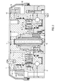
- the rotating device shown comprises a stator 1, which, for example can be connected to an excavator boom, not shown, and a rotor 2 rotatably mounted on the stator about an axis I, on which for example, an excavator grab, also not shown, can be attached.
- Stator 1 and rotor 2 can also be mounted upside down, so that the stator 1 becomes the rotor and the rotor 2 the stator.
- the drive acting between stator 1 and rotor 2 comprises a plurality from piston-cylinder arrangements arranged radially to the axis of rotation I in the stator 1 3.
- the cylinders of the piston-cylinder assemblies 3 are each by a circular cylindrical recess in cross section 4 formed in the stator 1, in which a piston 5 in the radial direction is slidably guided.
- a piston pressure chamber 7 educated.
- a compression spring 8 is in each case in this piston pressure chamber 7 arranged, on the one hand at the bottom 6 of the recess 4 and on the other supported on the piston 5.
- each roll-shaped rolling body 9 is provided, which on the piston 5 is rotatably mounted about an axis II parallel to axis I.
- compression spring 8 is a lifting of the rolling body 9 prevented by a curved path 10, which the piston 5 on the rotor 2 is provided opposite.
- the distance of the curved path 10 from the Axis of rotation I changes cyclically around axis of rotation I between a maximum distance at which the piston 5 is extended, and a minimum distance at which the piston 5 is retracted.
- a first external ring gear 13 is provided on the outer circumference of the stator 1, whose teeth are distributed around the axis of rotation I of the rotor 2 are. It is a full wreath, that is, the teeth are provided over the entire circumference of 360 °.
- Another external ring gear 14 is on the outer circumference of the rotor 2, the first outer ring gear 13 of the stator 1 arranged adjacent.
- the Teeth of the external ring gear 14 are also about the axis of rotation I des Rotors 2 arranged distributed and available over the entire circumference.
- the diameter of this second external ring gear 14 is correct corresponds to that of the first external ring gear 13. The diameter but could also be different.
- a switching ring 15 on the rotor 2 with an internal ring gear 16 provided.
- the switching ring 15 sits on the internal ring gear 16 the outer ring gear 14 of the rotor 2. That is, the teeth of the inner ring gear 16 are with the teeth of the external ring gear 14 in Intervention.
- the diameter of the internal ring gear 16 is dimensioned so that the switching ring 15 on the external ring gear 14 of the rotor 2 is axially displaceable and through the teeth of the external ring gear 14 is guided axially.
- the switching ring 15 and the teeth of its internal ring gear 16 have one width measured in the direction of the axis of rotation I, which is greater than that Width of the teeth of the external ring gear 14. This corresponds to Width is approximately the sum of the width of that provided on the rotor 2 Outer ring 14 of the width of the outer ring gear provided on the stator 1 13 and the space between them 17.
- the Inner ring gear 16 can thereby with the teeth of both outer ring gears 13 and 14 are fully engaged. This engagement position is shown in Fig. 2 shown on the right.
- the switching ring 15 is in the Fig. 2 shown on the left side disengaged position.
- the rotor 2 in this position relative to the stator 1 freely about the axis I be twisted. Now the rotor 2 should be in a certain rotational position can be locked relative to the stator 1, the switching ring 15 in the 2 on the right side shown in the engaged position axially adjusted become.
- the teeth of the internal ring gear engage 16 of the switching ring 15 both in the teeth of the external ring gear 13 of the stator 1 and in the teeth of the external ring gear 14 of the rotor 2.
- the rotor 2 can therefore not be rotated relative to the stator 1.
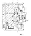
- Piston-cylinder units 19 are for actuating the switching ring 15 intended. Such is shown in Fig. 3. For example four such units 19 distributed over the circumference of the rotating device be arranged.
- the piston-cylinder unit 19 comprises one provided in the rotor 2 cylindrical receptacle 20 in which a double-sided piston 21 seals is led.
- the axis of displacement III of the piston 21 extends parallel to the axis of rotation I of the rotor 2 on both sides of the piston 21
- Piston pressure chambers 22 and 23 are formed, alternatively with hydraulic fluid are pressurizable.
- the piston 21 also has a piston rod 24, which with its other end is attached to the switching ring 15. A displacement of the piston 21 is thereby transferred to the switching ring 15, so that this is axially displaceable between two end positions.
- the one end position corresponds to that of the rotor 2 shown on the right in FIG. 2 removed engagement position and the other one in Fig. 2 on the left Side shown, the rotor 2 approximate disengaged position.
- four such piston-cylinder assemblies 19 can be tilt-free Shift of the switching ring 15 can be achieved. in principle but can also only three or more than four such piston-cylinder arrangements 19 or an annular piston can be provided.
- the outer sprockets 13 and 14 are directly in the outer circumference of the Stator 1 or the rotor 2 introduced. Basically it is but also possible to provide the external sprockets on separate rings, which are then attached to the stator 1 or the rotor 2. It is also possible to use two piston pressure chambers instead of a piston 22, 23 an arrangement with only one piston pressure chamber use and then a return spring on the other side of the piston provided.
- the teeth of the external ring gear 13 on the stator 1 and the teeth of the Internal ring gear 16 of the switching ring 15 are facing each other Side preferably bevelled. This will cause a move of the switching ring 15 from the disengaged position into the engaged position in every rotational position of the rotor 2 relative to the stator 1 ensured. Should an adjustment in the engaged position also during the rotation of the rotor 3 relative to the stator 1 are made possible, usual synchronization means can be provided for this.
- the adjustment of the switching ring 15 between its two positions is preferably carried out by a separate steering committee. This means, the piston-cylinder arrangement 19 is freely operable. An automatic Operation is also possible by controlling with the control circuit of the rotary drive is coupled.
Landscapes
- Engineering & Computer Science (AREA)
- Mechanical Engineering (AREA)
- Mining & Mineral Resources (AREA)
- Civil Engineering (AREA)
- General Engineering & Computer Science (AREA)
- Structural Engineering (AREA)
- Actuator (AREA)
- Retarders (AREA)
- Hydraulic Clutches, Magnetic Clutches, Fluid Clutches, And Fluid Joints (AREA)
Applications Claiming Priority (2)
| Application Number | Priority Date | Filing Date | Title |
|---|---|---|---|
| DE10300265 | 2003-01-08 | ||
| DE2003100265 DE10300265A1 (de) | 2003-01-08 | 2003-01-08 | Drehvorrichtung für Lastaufnahmemittel wie Baggergreifer und dergleichen |
Publications (2)
| Publication Number | Publication Date |
|---|---|
| EP1437323A1 true EP1437323A1 (fr) | 2004-07-14 |
| EP1437323B1 EP1437323B1 (fr) | 2017-09-20 |
Family
ID=32478163
Family Applications (1)
| Application Number | Title | Priority Date | Filing Date |
|---|---|---|---|
| EP04000230.5A Expired - Lifetime EP1437323B1 (fr) | 2003-01-08 | 2004-01-08 | Dispositif de rotation pour moyens de prise de charge comme des grapins d'excavatrice |
Country Status (2)
| Country | Link |
|---|---|
| EP (1) | EP1437323B1 (fr) |
| DE (1) | DE10300265A1 (fr) |
Cited By (4)
| Publication number | Priority date | Publication date | Assignee | Title |
|---|---|---|---|---|
| FR2869025A1 (fr) * | 2004-03-03 | 2005-10-21 | Linde Ag | Entrainement de dispositif de rotation a construction centrale |
| EP1674420A1 (fr) * | 2004-12-23 | 2006-06-28 | Heinz Thumm Oelhydraulische Antriebe GmbH | Dispositif de rotation pour moyens de prise de charge |
| EP3981727A1 (fr) * | 2020-10-06 | 2022-04-13 | LASCO Heutechnik GmbH | Couronne rotative, système de préhension, ainsi que grue |
| CN116292149A (zh) * | 2023-05-15 | 2023-06-23 | 内蒙古工业大学 | 一种双侧360°旋转且任意角度固定的旋转装置 |
Families Citing this family (1)
| Publication number | Priority date | Publication date | Assignee | Title |
|---|---|---|---|---|
| DE102008035088A1 (de) * | 2008-07-28 | 2010-02-04 | Av Hydraulikmotoren Gmbh | Hydraulikaggregat, insbesondere Hydraulikmotor |
Citations (4)
| Publication number | Priority date | Publication date | Assignee | Title |
|---|---|---|---|---|
| US5625967A (en) * | 1990-11-15 | 1997-05-06 | Kulle; Juergen | Device for controlling at least one attachment |
| EP0809736B1 (fr) * | 1995-02-18 | 1999-09-22 | Heinz Thumm Oelhydraulische Antriebe GmbH | Mecanisme vireur pour benne preneuse |
| EP1152092A1 (fr) * | 2001-07-20 | 2001-11-07 | Hans Neunteufel | Dispositif pour déplacer une tourelle sur un chassis ainsi qu'un véhicule, en particulier une excavatrice ou un chargeur, avec un tel déplacement de la tourelle |
| EP1170518A1 (fr) * | 2000-07-07 | 2002-01-09 | Skf Gmbh | Unité de palier verrouillable |
Family Cites Families (2)
| Publication number | Priority date | Publication date | Assignee | Title |
|---|---|---|---|---|
| DE19944987A1 (de) * | 1999-09-20 | 2001-03-22 | Heinz Thumm | Hydraulische Antriebsvorrichtung |
| DE10031472C1 (de) * | 2000-06-28 | 2002-04-18 | Tacke Windenergie Gmbh | Vorrichtung zur Arretierung einer von einem Rotor angetriebenen Welle einer Windkraftanlage |
-
2003
- 2003-01-08 DE DE2003100265 patent/DE10300265A1/de not_active Ceased
-
2004
- 2004-01-08 EP EP04000230.5A patent/EP1437323B1/fr not_active Expired - Lifetime
Patent Citations (4)
| Publication number | Priority date | Publication date | Assignee | Title |
|---|---|---|---|---|
| US5625967A (en) * | 1990-11-15 | 1997-05-06 | Kulle; Juergen | Device for controlling at least one attachment |
| EP0809736B1 (fr) * | 1995-02-18 | 1999-09-22 | Heinz Thumm Oelhydraulische Antriebe GmbH | Mecanisme vireur pour benne preneuse |
| EP1170518A1 (fr) * | 2000-07-07 | 2002-01-09 | Skf Gmbh | Unité de palier verrouillable |
| EP1152092A1 (fr) * | 2001-07-20 | 2001-11-07 | Hans Neunteufel | Dispositif pour déplacer une tourelle sur un chassis ainsi qu'un véhicule, en particulier une excavatrice ou un chargeur, avec un tel déplacement de la tourelle |
Cited By (4)
| Publication number | Priority date | Publication date | Assignee | Title |
|---|---|---|---|---|
| FR2869025A1 (fr) * | 2004-03-03 | 2005-10-21 | Linde Ag | Entrainement de dispositif de rotation a construction centrale |
| EP1674420A1 (fr) * | 2004-12-23 | 2006-06-28 | Heinz Thumm Oelhydraulische Antriebe GmbH | Dispositif de rotation pour moyens de prise de charge |
| EP3981727A1 (fr) * | 2020-10-06 | 2022-04-13 | LASCO Heutechnik GmbH | Couronne rotative, système de préhension, ainsi que grue |
| CN116292149A (zh) * | 2023-05-15 | 2023-06-23 | 内蒙古工业大学 | 一种双侧360°旋转且任意角度固定的旋转装置 |
Also Published As
| Publication number | Publication date |
|---|---|
| DE10300265A1 (de) | 2004-07-22 |
| EP1437323B1 (fr) | 2017-09-20 |
Similar Documents
| Publication | Publication Date | Title |
|---|---|---|
| DE2338275C2 (de) | Synchronisierungsvorrichtung | |
| DE102009037268B3 (de) | Variabler Ventiltrieb für Brennkraftmaschinen zur Betätigung von Gaswechselventilen | |
| EP0724924B1 (fr) | Porte-outil, en particulier mandrin à changement rapide | |
| WO2010115399A1 (fr) | Mécanisme de distribution pour moteurs à combustion interne pour l'actionnement de soupapes d'échange des gaz | |
| EP1251299A2 (fr) | Dispositif de commande pour automatiser le changement de vitesse pour boíte de vitesses manuelle des véhicules automobiles | |
| DE3227272A1 (de) | Winkelteilungsvorrichtung fuer werkzeugaufspanntische, werkzeugrevolverscheiben oder dergleichen | |
| EP0343329A2 (fr) | Dispositif d'indexation | |
| DE3817893C2 (fr) | ||
| DE3411054C2 (fr) | ||
| DE3611962C2 (fr) | ||
| CH631532A5 (de) | Stellungsgeber zum melden der stellung eines organs, insbesondere eines stellgliedes, und verwendung des stellungsgebers. | |
| DE3616915C2 (fr) | ||
| EP1437323B1 (fr) | Dispositif de rotation pour moyens de prise de charge comme des grapins d'excavatrice | |
| EP0598207B1 (fr) | Mandrin de forage | |
| DE102009054879A1 (de) | Axialverstelleinrichtung, beispielsweise für eine Kupplung eines Getriebes oder eine Differentialsperre eines Kraftfahrzeuges | |
| DE3342471C2 (fr) | ||
| EP1304495B1 (fr) | Accouplement à limitation de couple | |
| DE19959833C1 (de) | Schließvorrichtung für insbesondere an Fahrzeugen vollziehbare Schließfunktionen | |
| DE102005056992B4 (de) | Drehsteller für elektrische oder elektronische Geräte in einem Kraftfahrzeug | |
| EP2487325A2 (fr) | Système de positionnement mécanique d'une clé d'interception et/ou d'une clé de rupture sur une tige de forage ainsi que machine de forage | |
| DE3636856C2 (fr) | ||
| EP0853991B1 (fr) | Tête de roulage radial | |
| DE102006016666A1 (de) | Vorrichtung zur Betätigung einer Kupplung | |
| EP1085205B1 (fr) | Transmission hydraulique | |
| DE2346849C2 (de) | Revolverkopf für Werkzeuge |
Legal Events
| Date | Code | Title | Description |
|---|---|---|---|
| PUAI | Public reference made under article 153(3) epc to a published international application that has entered the european phase |
Free format text: ORIGINAL CODE: 0009012 |
|
| AK | Designated contracting states |
Kind code of ref document: A1 Designated state(s): AT BE BG CH CY CZ DE DK EE ES FI FR GB GR HU IE IT LI LU MC NL PT RO SE SI SK TR |
|
| AX | Request for extension of the european patent |
Extension state: AL LT LV MK |
|
| 17P | Request for examination filed |
Effective date: 20050114 |
|
| AKX | Designation fees paid |
Designated state(s): AT BE BG CH CY CZ DE DK EE ES FI FR GB GR HU IE IT LI LU MC NL PT RO SE SI SK TR |
|
| 17Q | First examination report despatched |
Effective date: 20090312 |
|
| STAA | Information on the status of an ep patent application or granted ep patent |
Free format text: STATUS: EXAMINATION IS IN PROGRESS |
|
| GRAP | Despatch of communication of intention to grant a patent |
Free format text: ORIGINAL CODE: EPIDOSNIGR1 |
|
| STAA | Information on the status of an ep patent application or granted ep patent |
Free format text: STATUS: GRANT OF PATENT IS INTENDED |
|
| INTG | Intention to grant announced |
Effective date: 20170630 |
|
| GRAS | Grant fee paid |
Free format text: ORIGINAL CODE: EPIDOSNIGR3 |
|
| GRAA | (expected) grant |
Free format text: ORIGINAL CODE: 0009210 |
|
| STAA | Information on the status of an ep patent application or granted ep patent |
Free format text: STATUS: THE PATENT HAS BEEN GRANTED |
|
| AK | Designated contracting states |
Kind code of ref document: B1 Designated state(s): AT BE BG CH CY CZ DE DK EE ES FI FR GB GR HU IE IT LI LU MC NL PT RO SE SI SK TR |
|
| REG | Reference to a national code |
Ref country code: GB Ref legal event code: FG4D Free format text: NOT ENGLISH |
|
| REG | Reference to a national code |
Ref country code: CH Ref legal event code: EP |
|
| REG | Reference to a national code |
Ref country code: AT Ref legal event code: REF Ref document number: 929958 Country of ref document: AT Kind code of ref document: T Effective date: 20171015 |
|
| REG | Reference to a national code |
Ref country code: IE Ref legal event code: FG4D Free format text: LANGUAGE OF EP DOCUMENT: GERMAN |
|
| REG | Reference to a national code |
Ref country code: DE Ref legal event code: R096 Ref document number: 502004015587 Country of ref document: DE |
|
| REG | Reference to a national code |
Ref country code: SE Ref legal event code: TRGR |
|
| REG | Reference to a national code |
Ref country code: NL Ref legal event code: MP Effective date: 20170920 |
|
| PG25 | Lapsed in a contracting state [announced via postgrant information from national office to epo] |
Ref country code: FI Free format text: LAPSE BECAUSE OF FAILURE TO SUBMIT A TRANSLATION OF THE DESCRIPTION OR TO PAY THE FEE WITHIN THE PRESCRIBED TIME-LIMIT Effective date: 20170920 |
|
| PG25 | Lapsed in a contracting state [announced via postgrant information from national office to epo] |
Ref country code: BG Free format text: LAPSE BECAUSE OF FAILURE TO SUBMIT A TRANSLATION OF THE DESCRIPTION OR TO PAY THE FEE WITHIN THE PRESCRIBED TIME-LIMIT Effective date: 20171220 Ref country code: GR Free format text: LAPSE BECAUSE OF FAILURE TO SUBMIT A TRANSLATION OF THE DESCRIPTION OR TO PAY THE FEE WITHIN THE PRESCRIBED TIME-LIMIT Effective date: 20171221 |
|
| PG25 | Lapsed in a contracting state [announced via postgrant information from national office to epo] |
Ref country code: NL Free format text: LAPSE BECAUSE OF FAILURE TO SUBMIT A TRANSLATION OF THE DESCRIPTION OR TO PAY THE FEE WITHIN THE PRESCRIBED TIME-LIMIT Effective date: 20170920 |
|
| PG25 | Lapsed in a contracting state [announced via postgrant information from national office to epo] |
Ref country code: CZ Free format text: LAPSE BECAUSE OF FAILURE TO SUBMIT A TRANSLATION OF THE DESCRIPTION OR TO PAY THE FEE WITHIN THE PRESCRIBED TIME-LIMIT Effective date: 20170920 Ref country code: ES Free format text: LAPSE BECAUSE OF FAILURE TO SUBMIT A TRANSLATION OF THE DESCRIPTION OR TO PAY THE FEE WITHIN THE PRESCRIBED TIME-LIMIT Effective date: 20170920 Ref country code: RO Free format text: LAPSE BECAUSE OF FAILURE TO SUBMIT A TRANSLATION OF THE DESCRIPTION OR TO PAY THE FEE WITHIN THE PRESCRIBED TIME-LIMIT Effective date: 20170920 |
|
| PG25 | Lapsed in a contracting state [announced via postgrant information from national office to epo] |
Ref country code: EE Free format text: LAPSE BECAUSE OF FAILURE TO SUBMIT A TRANSLATION OF THE DESCRIPTION OR TO PAY THE FEE WITHIN THE PRESCRIBED TIME-LIMIT Effective date: 20170920 Ref country code: SK Free format text: LAPSE BECAUSE OF FAILURE TO SUBMIT A TRANSLATION OF THE DESCRIPTION OR TO PAY THE FEE WITHIN THE PRESCRIBED TIME-LIMIT Effective date: 20170920 |
|
| REG | Reference to a national code |
Ref country code: DE Ref legal event code: R097 Ref document number: 502004015587 Country of ref document: DE |
|
| PLBE | No opposition filed within time limit |
Free format text: ORIGINAL CODE: 0009261 |
|
| STAA | Information on the status of an ep patent application or granted ep patent |
Free format text: STATUS: NO OPPOSITION FILED WITHIN TIME LIMIT |
|
| PG25 | Lapsed in a contracting state [announced via postgrant information from national office to epo] |
Ref country code: DK Free format text: LAPSE BECAUSE OF FAILURE TO SUBMIT A TRANSLATION OF THE DESCRIPTION OR TO PAY THE FEE WITHIN THE PRESCRIBED TIME-LIMIT Effective date: 20170920 |
|
| 26N | No opposition filed |
Effective date: 20180621 |
|
| REG | Reference to a national code |
Ref country code: CH Ref legal event code: PL |
|
| GBPC | Gb: european patent ceased through non-payment of renewal fee |
Effective date: 20180108 |
|
| PG25 | Lapsed in a contracting state [announced via postgrant information from national office to epo] |
Ref country code: FR Free format text: LAPSE BECAUSE OF NON-PAYMENT OF DUE FEES Effective date: 20180131 Ref country code: LU Free format text: LAPSE BECAUSE OF NON-PAYMENT OF DUE FEES Effective date: 20180108 |
|
| REG | Reference to a national code |
Ref country code: IE Ref legal event code: MM4A |
|
| REG | Reference to a national code |
Ref country code: FR Ref legal event code: ST Effective date: 20180928 |
|
| REG | Reference to a national code |
Ref country code: BE Ref legal event code: MM Effective date: 20180131 |
|
| PG25 | Lapsed in a contracting state [announced via postgrant information from national office to epo] |
Ref country code: BE Free format text: LAPSE BECAUSE OF NON-PAYMENT OF DUE FEES Effective date: 20180131 Ref country code: SI Free format text: LAPSE BECAUSE OF FAILURE TO SUBMIT A TRANSLATION OF THE DESCRIPTION OR TO PAY THE FEE WITHIN THE PRESCRIBED TIME-LIMIT Effective date: 20170920 Ref country code: CH Free format text: LAPSE BECAUSE OF NON-PAYMENT OF DUE FEES Effective date: 20180131 Ref country code: GB Free format text: LAPSE BECAUSE OF NON-PAYMENT OF DUE FEES Effective date: 20180108 Ref country code: LI Free format text: LAPSE BECAUSE OF NON-PAYMENT OF DUE FEES Effective date: 20180131 |
|
| PG25 | Lapsed in a contracting state [announced via postgrant information from national office to epo] |
Ref country code: IE Free format text: LAPSE BECAUSE OF NON-PAYMENT OF DUE FEES Effective date: 20180108 |
|
| REG | Reference to a national code |
Ref country code: AT Ref legal event code: MM01 Ref document number: 929958 Country of ref document: AT Kind code of ref document: T Effective date: 20180108 |
|
| PG25 | Lapsed in a contracting state [announced via postgrant information from national office to epo] |
Ref country code: AT Free format text: LAPSE BECAUSE OF NON-PAYMENT OF DUE FEES Effective date: 20180108 |
|
| PG25 | Lapsed in a contracting state [announced via postgrant information from national office to epo] |
Ref country code: MC Free format text: LAPSE BECAUSE OF FAILURE TO SUBMIT A TRANSLATION OF THE DESCRIPTION OR TO PAY THE FEE WITHIN THE PRESCRIBED TIME-LIMIT Effective date: 20170920 |
|
| PG25 | Lapsed in a contracting state [announced via postgrant information from national office to epo] |
Ref country code: TR Free format text: LAPSE BECAUSE OF FAILURE TO SUBMIT A TRANSLATION OF THE DESCRIPTION OR TO PAY THE FEE WITHIN THE PRESCRIBED TIME-LIMIT Effective date: 20170920 |
|
| PG25 | Lapsed in a contracting state [announced via postgrant information from national office to epo] |
Ref country code: PT Free format text: LAPSE BECAUSE OF FAILURE TO SUBMIT A TRANSLATION OF THE DESCRIPTION OR TO PAY THE FEE WITHIN THE PRESCRIBED TIME-LIMIT Effective date: 20170920 Ref country code: HU Free format text: LAPSE BECAUSE OF FAILURE TO SUBMIT A TRANSLATION OF THE DESCRIPTION OR TO PAY THE FEE WITHIN THE PRESCRIBED TIME-LIMIT; INVALID AB INITIO Effective date: 20040108 |
|
| PG25 | Lapsed in a contracting state [announced via postgrant information from national office to epo] |
Ref country code: CY Free format text: LAPSE BECAUSE OF FAILURE TO SUBMIT A TRANSLATION OF THE DESCRIPTION OR TO PAY THE FEE WITHIN THE PRESCRIBED TIME-LIMIT Effective date: 20170920 |
|
| PGFP | Annual fee paid to national office [announced via postgrant information from national office to epo] |
Ref country code: SE Payment date: 20220620 Year of fee payment: 19 Ref country code: IT Payment date: 20220627 Year of fee payment: 19 Ref country code: DE Payment date: 20220628 Year of fee payment: 19 |
|
| REG | Reference to a national code |
Ref country code: DE Ref legal event code: R119 Ref document number: 502004015587 Country of ref document: DE |
|
| REG | Reference to a national code |
Ref country code: SE Ref legal event code: EUG |
|
| PG25 | Lapsed in a contracting state [announced via postgrant information from national office to epo] |
Ref country code: SE Free format text: LAPSE BECAUSE OF NON-PAYMENT OF DUE FEES Effective date: 20230109 Ref country code: DE Free format text: LAPSE BECAUSE OF NON-PAYMENT OF DUE FEES Effective date: 20230801 |
|
| PG25 | Lapsed in a contracting state [announced via postgrant information from national office to epo] |
Ref country code: IT Free format text: LAPSE BECAUSE OF NON-PAYMENT OF DUE FEES Effective date: 20230108 |