EP2487325A2 - Système de positionnement mécanique d'une clé d'interception et/ou d'une clé de rupture sur une tige de forage ainsi que machine de forage - Google Patents
Système de positionnement mécanique d'une clé d'interception et/ou d'une clé de rupture sur une tige de forage ainsi que machine de forage Download PDFInfo
- Publication number
- EP2487325A2 EP2487325A2 EP20120154731 EP12154731A EP2487325A2 EP 2487325 A2 EP2487325 A2 EP 2487325A2 EP 20120154731 EP20120154731 EP 20120154731 EP 12154731 A EP12154731 A EP 12154731A EP 2487325 A2 EP2487325 A2 EP 2487325A2
- Authority
- EP
- European Patent Office
- Prior art keywords
- key
- handling device
- breaking
- interceptor
- segments
- Prior art date
- Legal status (The legal status is an assumption and is not a legal conclusion. Google has not performed a legal analysis and makes no representation as to the accuracy of the status listed.)
- Withdrawn
Links
- 238000005553 drilling Methods 0.000 title description 7
- 238000000926 separation method Methods 0.000 claims description 2
- 238000006073 displacement reaction Methods 0.000 description 8
- 238000000034 method Methods 0.000 description 8
- 240000006829 Ficus sundaica Species 0.000 description 3
- 230000005540 biological transmission Effects 0.000 description 2
- 230000008878 coupling Effects 0.000 description 2
- 238000010168 coupling process Methods 0.000 description 2
- 238000005859 coupling reaction Methods 0.000 description 2
- 230000006378 damage Effects 0.000 description 2
- 230000000694 effects Effects 0.000 description 2
- 206010047700 Vomiting Diseases 0.000 description 1
- 208000027418 Wounds and injury Diseases 0.000 description 1
- 238000010521 absorption reaction Methods 0.000 description 1
- 230000000295 complement effect Effects 0.000 description 1
- 208000014674 injury Diseases 0.000 description 1
- 238000003780 insertion Methods 0.000 description 1
- 230000037431 insertion Effects 0.000 description 1
- 238000004519 manufacturing process Methods 0.000 description 1
- 230000005693 optoelectronics Effects 0.000 description 1
- 239000007787 solid Substances 0.000 description 1
- 230000008673 vomiting Effects 0.000 description 1
Images



Classifications
-
- E—FIXED CONSTRUCTIONS
- E21—EARTH OR ROCK DRILLING; MINING
- E21B—EARTH OR ROCK DRILLING; OBTAINING OIL, GAS, WATER, SOLUBLE OR MELTABLE MATERIALS OR A SLURRY OF MINERALS FROM WELLS
- E21B19/00—Handling rods, casings, tubes or the like outside the borehole, e.g. in the derrick; Apparatus for feeding the rods or cables
- E21B19/16—Connecting or disconnecting pipe couplings or joints
- E21B19/167—Connecting or disconnecting pipe couplings or joints using a wrench adapted to engage a non circular section of pipe, e.g. a section with flats or splines
Definitions
- the invention relates to a system comprising a handling device and a interceptor key and / or a breaker key for mechanically attaching or detaching the interceptor key and / or the breaker key to or from a drill string segment of a drill pipe, and a raise-boring machine equipped with this system.
- up-drilling is a drilling process in which a circular well can be made between a subterranean cavity and a higher level, drilling downhole from a pilot hole. This method is used in particular for the production of connections between two routes in a mine or between a cavern and the earth's surface.
- an extension tool is mounted at the base of the bore on a drill pipe comprising a plurality of drill string segments bolted together. To extend the pilot hole, the drill pipe is rotated and caught up. Each time a drill string segment length is drilled, a drill string segment must be removed.
- the drill string is intercepted below the segment to be removed, for which an interceptor is provided. It includes a intercept key, which is engageable with a key surface provided in the upper portion of a second drill string segment following the first upper drill string segment to be excavated downwardly.
- the interceptor is this often pushed manually on the key area. Since this process occurs in the work space of the raise boring machine, i. within the space bounded by the machine frame, it is associated with a high accident risk. This is especially true when the Raise Boring machine is used to expand a perpendicular to the vertical inclined pilot hole, as an attached interceptor in the case of mounting positions in which the tines are inclined upwards, tends to unwanted dropping.
- this segment also by a rotary actuator of the drill string force rotary head with which it is screwed, a breaking key on the key area in the upper part of this first BohrgestShesegments manually pushed and this segment rotates thereby.
- a release of the power rotary head then takes place by the rotational actuation in the loosening direction. Also, there is a risk in this process that the wrench falls off and injured persons in the working space of the Raise Boring machine or damaged technical equipment.
- the invention is therefore based on the object to provide a system by means of which the risk of injury and damage is reduced.
- the invention comprises a handling device and a intercepting key and / or a breaking key for mechanically attaching or detaching the intercepting key and / or the breaking key to or from a drill string segment a drill string, in particular a raise boring machine.
- the interception keys and / or breaker keys are rotatably and / or removably arranged on the handling device. Due to this measure, after setting the interceptor key, the drill pipe can be mechanically turned into an angular position by means of the power swivel head before lowering into the interceptor, in which also the breaking key can be machined.
- the handling device is removably provided by the interceptor. If there is enough workspace available, the removable design can be dispensed with. The same applies mutatis mutandis to the design of the handling device for the vomiting key and the latter itself.
- the handling device may comprise at least two jaws or levers which are engageable by means of an actuator between an open position in which the interceptor key or breaker key is attachable to the drill string segment and a closed position in which the interceptor key is in its closed position in which it cooperates with key surfaces on the BohrgestShesegment, are displaced.
- the interceptor key and / or the breaker key may have a plurality of segments and cooperate with the handling device such that the interceptor key and / or the breaker key can be attached to the drill string segment in a direction oblique or transverse to the longitudinal axis of the drill string in the open position of the handling device ,
- the interceptor key and / or the breaking key has a number of segments which corresponds to the number of jaws or levers of the handling device. Each jaw or lever may then cooperate with a segment of the interceptor key, whereby the mechanical coupling between the jaws or levers and the segments may be readily formed.
- the handling device may comprise entrainment elements that engage at least one of the interceptor keys and / or the crusher-provided receptacle can be brought into engagement.
- the at least one receptacle as a groove which is circular in the closed position of the segments and is provided on an end face of the intercepting key and / or the refractive key. Due to the circularity it is ensured that the interceptor key and / or the break key can rotate in the closed position in the handling device.
- the driver elements for example, their outer diameter slightly smaller than the groove width, a removability of the handling device of the interceptor and / or the breaking key is realized in a structurally simple manner.
- the groove In order to reduce the risk that the interceptor and / or the wrench automatically dissolves during the piecing or removal process of the respective handling device, it is preferred to form the groove with an undercut, in which then at least one driver element in the open state befindliches handling device engages.
- the segments of the interceptor key and / or the breaker key may be hinged together, with the exception of a separation point between two mutually facing ends of adjacent segments.
- the driver elements are then always on a flank, preferably an undercut edge of the groove during the handling process, means are preferably provided which act on the segments with a force acting in the closing direction force.
- These means may in particular be spring elements or magnetically acting means.
- the invention also relates to a raise-boring machine equipped with a system of the type described above.
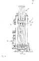
- the designated in the drawing as a whole with 100 Raise Boring machine (hereinafter also only briefly “machine”) comprises a machine frame 1, on which a rotary drive means 2 by means of hydraulically actuated piston / cylinder units 3 in the longitudinal direction of a drill string 4 is displaceably guided.
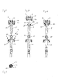
- the drill string 4 comprises a plurality of drill string segments, of which in Fig. 4 only the upper, first BohrgestCodesegment 5, a second, adjoining the first BohrgestCodesegment 5 below BohrgestTempesegment 6 and another, adjoining the second BohrgestShesegment 6 BohrgestHaresegment 7 are shown.
- the raise-boring machine 100 is used to extend a pilot hole from bottom to top, for which purpose on the not visible in the drawing, lower end of the drill string 4 an extension tool, such as a Bohrlochsammlungr is mounted in a known manner.
- the rotary drive device 2 which comprises a flanged gear 8 with a main shaft 9 with a threaded receptacle 10, on a complementary external thread 11 of the upper end of that BohrgestShesegments 5, 6, 7 screwed, which is held by a support device 12 (s. Fig. 10 ).
- the first BohrgestShesegment 5 comprises at its lower end a threaded receptacle 14 which corresponds approximately to the threaded receptacle 10 on the main shaft 9, the upper end 13 of the second BohrgestShesegments 6 an external thread 15, which the external thread 11 corresponds.
- the first drill string segment 5 In order to be able to continue driving the bore upward, the first drill string segment 5 must be removed and the rotary drive device 2 then screwed to the upper end 13 of the second drill pipe segment 6.
- a catch receptacle 21 is provided on the machine frame 1 of the raise boring machine 100, which surrounds the drill pipe 4 approximately concentrically. It serves to receive a interception key 17, which is designed like a clamp and can be placed around the drill string (see in particular FIG Fig. 4 ).
- the interception key comprises four key surfaces 18, which are arranged in the closed state of the interceptor key 17 at an angle of 90 ° to each other.
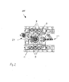
- a motor-driven handling device 20 For mechanically attaching and removing the interception key 17 is a motor-driven handling device 20. It is designed such that the interceptor 17 between a in Fig. 2 shown, outer position and the drill string 4 enclosing position is approximately perpendicular to the longitudinal axis L displaced and the interception key 17 can be opened and closed. Their exact design and operation will be explained below with reference to the Fig. 12 to 17 will be explained in more detail.
- the interceptor key 17 After attaching and closing the interceptor key 17 with the aid of the handling device 20, the interceptor key 17 completely surrounds the drill pipe 4 and its key surfaces 19 co-operate flatly with the flats 18 of the segment 6 of the drill string 4, as shown in FIG Fig. 6 is shown, the handling device 20 is moved back and the drill pipe 4 in his in Fig. 5 shifted position shown. In this rests the interceptor key 17 in a rotatably disposed within the machine frame interceptor 21st
- the interceptor key 17 comprises, on its outer surface, a face toothing 22 which engages in an internal toothing 23 of the interception mount 21, which in FIG Fig. 11 is shown.
- the spur gear teeth 22 and the internal teeth 23 are formed such that the interceptor key 17 in the interceptor 21 has a backlash of about twice the tooth pitch.
- each second tooth of the toothing is not formed both in the spur toothing 22 and in the internal toothing 23. The torsional backlash facilitates the insertion of the interceptor key 17 into the interceptor 21.
- Both the breaking key 25 and the Brechability 26 have front or internal teeth, which correspond to the front or inner teeth 22, 23 of the interception key 17 and the interceptor 21.
- the drill rod segment 5 detached from the second drill string segment 6 is subsequently held by means of a manipulator 27, which in FIG Fig. 1 . 2 and 9 is recognizable.
- the rotary drive device 2 After removal of the first BohrgestCodesegments 5 using the manipulator 27, the rotary drive device 2 is lowered and bolted to the external thread 15 of the drill pipe segment 6 below, the drill pipe 4 is raised with the rotary drive device 2 until the interception key 17 can be removed with the handling device 24. After removal, the drilling operation is continued by rotational operation and lifting of the rotary drive device 2.
- the raise-boring machine 100 further includes an in Fig. 3 also only schematically illustrated Drehwinkelaufillon 30 which cooperates with the main shaft of the transmission 2 and detects its rotation angle. It is connected to a programmable logic controller 31, which comprises a drive control 32 for the rotary drive device 2, which - depending on the type of rotary drive - can work in particular electrically or electro-hydraulically.
- the programmable logic controller is programmed so that after applying the refractive key 25 and engaging with the crushing receptacle 26 for releasing screwed together drill string segments 5, 6, a reverse rotation of the rotary drive means takes place by a rotation angle that allows a machine removal of the breaker key, preferably a multiple of full revolutions.
- a reverse rotation of the rotary drive means takes place by a rotation angle that allows a machine removal of the breaker key, preferably a multiple of full revolutions.
- FIG. 12 to 17 An embodiment of a handling device, which can be used both as a handling device 20 for the intercepting key 17, and as a handling device 24 for the breaking key 25 and therefore hereinafter referred to as "the handling device 20, 24" will now be described in detail with reference to the Fig. 12 to 17 to be discribed.
- the handling device 20, 24 comprises a mounting device 33 with which it can be attached to the machine frame 33.
- two levers 34, 35 are pivotally mounted about axes parallel to the longitudinal axis 11, which are pivotally connected at their other ends to axes A parallel to the axes S with a base 36 of the handling device 20, 24.
- the handling device 20, 24 can therefore be on a circular arc, the radius of which is predetermined by the length of the lever 34, 35, without changing the angle of the base 36 to the machine frame substantially. This displacement possibility serves to the handling device 24, 26 from the in Fig.
- 24 are two levers 39, 40 about a common axis X to each other and to the base 36 pivotally mounted.
- a hydraulically operating actuator 41 is disposed on the base 36. It comprises a piston rod 42, on whose levers 39, 40 facing the end two Anlenklaschen 43, 44 are articulated about a parallel to the axis X pivotable axis Y respectively with their first ends.
- the Anlenklaschen 43, 44 are coupled with their second ends respectively to one of the levers 39, 40 about the axis Y parallel axes Z.
- the axes Z are located both in the open, in Fig. 12 and in Fig.
- 40 driving elements 45 are provided on the levers 39, which protrude from the surface 46 of the lever 39, 40.
- the driver elements are designed as hexagon socket screws and screwed into corresponding threaded holes in the levers 39, 40.
- the driver elements 45 serve to entrain the interception key 17 or the breaking key 25, depending on which the handling device 20, 24 is provided.
- 38, grooves 47, 48 are incorporated into the lower end faces of the segments 37, such that in the closed state of the segments 37, 38 results in an annular groove, as in Fig. 13 is clarified.
- the segments 37, 38 with closed handling device 20, 24 rotate about the longitudinal axis L, so that the handling device does not need to be removed, for example, when positioning the key surfaces 19 of another BohrgestShesegments the drill pipe must be rotated about its longitudinal axis L.
- the handling device can in principle also during a crushing operation in the in Fig. 13 remain position shown, provided that it is mounted displaceable in the direction of the longitudinal axis L on the machine frame and the working space of the machine includes sufficient space for this purpose.
- the interceptor key or breaker key 17, 25 can also be attached to the handling device 20, 24 only on the key surfaces 18 provided for this purpose, and then the handling device 20, 24 can be displaced downwards to such an extent Mit Converselus 45 have been completely shifted out of the grooves 47, 48 out. Subsequently, the levers 39, 40 are displaced by actuation of the actuator 41 in the open position and the handling device are moved out of the working space of the machine.
- the interceptor or breaker key 17, 25 does not open unintentionally before entering the interception or crushing receptacle 21, 26, means are provided on the segments 37, 38, which act on the segments with a force acting in the closing direction. These means may be magnetically acting means, for example, cause a magnetic attraction of the segments 37, 38 to each other or to the drill pipe 4. Alternatively or additionally, a spring element which acts about the axis X about which the segments 37, 38 are connected to one another in an articulated manner can be provided.
- the grooves 47, 48 are each provided with an undercut 49 radially outward.
- the driver elements 45 slightly increase when the segments 37, 38 are open against the force acting in the closing direction during the handling process.
- two positioning pins 50 are provided on the base 36, which pass through the levers 39, 40 in slot-like apertures 51 and where the interception - And crushing wrench 17, 25 abut with their spur teeth in the open position (s. Fig. 12 ).
- the handling device 20, 24 and the intercepting and / or breaking keys 17, 25 together form a system 60, by means of which machine interceptor or breaker key 17, 25 attached to a drill pipe 4 or can be removed from this again, as by the above Designs has become clear.
Landscapes
- Engineering & Computer Science (AREA)
- Life Sciences & Earth Sciences (AREA)
- Geology (AREA)
- Mining & Mineral Resources (AREA)
- Mechanical Engineering (AREA)
- Physics & Mathematics (AREA)
- Environmental & Geological Engineering (AREA)
- Fluid Mechanics (AREA)
- General Life Sciences & Earth Sciences (AREA)
- Geochemistry & Mineralogy (AREA)
- Earth Drilling (AREA)
Applications Claiming Priority (1)
| Application Number | Priority Date | Filing Date | Title |
|---|---|---|---|
| DE201110000688 DE102011000688A1 (de) | 2011-02-14 | 2011-02-14 | System zum maschinellen Ansetzen eines Abfangschlüssels und/oder eines Brechschlüssels an ein Bohrgestänge sowie Raise-Boring-Maschine |
Publications (1)
| Publication Number | Publication Date |
|---|---|
| EP2487325A2 true EP2487325A2 (fr) | 2012-08-15 |
Family
ID=45655530
Family Applications (1)
| Application Number | Title | Priority Date | Filing Date |
|---|---|---|---|
| EP20120154731 Withdrawn EP2487325A2 (fr) | 2011-02-14 | 2012-02-09 | Système de positionnement mécanique d'une clé d'interception et/ou d'une clé de rupture sur une tige de forage ainsi que machine de forage |
Country Status (2)
| Country | Link |
|---|---|
| EP (1) | EP2487325A2 (fr) |
| DE (1) | DE102011000688A1 (fr) |
Cited By (4)
| Publication number | Priority date | Publication date | Assignee | Title |
|---|---|---|---|---|
| WO2016140614A1 (fr) * | 2015-03-04 | 2016-09-09 | Atlas Copco Rock Drills Ab | Dispositif et procédé de forage de roche |
| CN116084863A (zh) * | 2023-03-24 | 2023-05-09 | 莱州亚通重型装备有限公司 | 一种带护杆导向功能的拆卸钻杆装置 |
| US12196047B2 (en) * | 2021-07-30 | 2025-01-14 | Dv Technology Spa | Automatic tricone exchange, storage and lubrication system |
| WO2026049658A1 (fr) * | 2024-08-26 | 2026-03-05 | Epiroc Rock Drills Aktiebolag | Procédé et agencement de manipulation de train de tiges de forage pour manipuler des zones de préhension d'un composant de train de tiges de forage avec une unité de clé |
Citations (1)
| Publication number | Priority date | Publication date | Assignee | Title |
|---|---|---|---|---|
| US3771389A (en) | 1972-05-19 | 1973-11-13 | Ingersoll Rand Co | Motorized tool assembly for drill rods |
-
2011
- 2011-02-14 DE DE201110000688 patent/DE102011000688A1/de not_active Withdrawn
-
2012
- 2012-02-09 EP EP20120154731 patent/EP2487325A2/fr not_active Withdrawn
Patent Citations (1)
| Publication number | Priority date | Publication date | Assignee | Title |
|---|---|---|---|---|
| US3771389A (en) | 1972-05-19 | 1973-11-13 | Ingersoll Rand Co | Motorized tool assembly for drill rods |
Cited By (5)
| Publication number | Priority date | Publication date | Assignee | Title |
|---|---|---|---|---|
| WO2016140614A1 (fr) * | 2015-03-04 | 2016-09-09 | Atlas Copco Rock Drills Ab | Dispositif et procédé de forage de roche |
| AU2016226645B2 (en) * | 2015-03-04 | 2021-04-08 | Epiroc Rock Drills Aktiebolag | Device and method in respect of rock boring |
| US12196047B2 (en) * | 2021-07-30 | 2025-01-14 | Dv Technology Spa | Automatic tricone exchange, storage and lubrication system |
| CN116084863A (zh) * | 2023-03-24 | 2023-05-09 | 莱州亚通重型装备有限公司 | 一种带护杆导向功能的拆卸钻杆装置 |
| WO2026049658A1 (fr) * | 2024-08-26 | 2026-03-05 | Epiroc Rock Drills Aktiebolag | Procédé et agencement de manipulation de train de tiges de forage pour manipuler des zones de préhension d'un composant de train de tiges de forage avec une unité de clé |
Also Published As
| Publication number | Publication date |
|---|---|
| DE102011000688A1 (de) | 2012-08-16 |
| DE102011000688A8 (de) | 2012-10-18 |
Similar Documents
| Publication | Publication Date | Title |
|---|---|---|
| DE102010062418B9 (de) | Verfahren und Vorrichtung zum Verdrehen eines Roboterblattlagers an Windenergieanlagen ohne Einsatz eines Autokranes | |
| EP2078585B1 (fr) | Dispositif mécanique destiné au montage et/ou au démontage d'une tuyère laser et machine de traitement laser dotée d'un tel dispositif mécanique | |
| DE102012008252B4 (de) | Fräseinrichtung für eine Bodenfräsmaschine, Fräswalze für eine solche Fräseinrichtung und Bodenfräsmaschine mit einer solchen Fräseinrichtung | |
| EP2708327B1 (fr) | Dispositif de serrage pour l'expansion d'un boulon fileté et outil approprié, de préférence adaptateur d'entraînement | |
| DE3642387C2 (fr) | ||
| DE60219774T2 (de) | Ventilsperrvorrichtung | |
| EP3371418B1 (fr) | Haveuse chargeuse | |
| EP2487325A2 (fr) | Système de positionnement mécanique d'une clé d'interception et/ou d'une clé de rupture sur une tige de forage ainsi que machine de forage | |
| DE2442798A1 (de) | Vorrichtung fuer schraubenverbindungen | |
| DE102013009116B4 (de) | Weichenantrieb für ein Eisenbahngleis | |
| DE69908343T2 (de) | System und verfahren zur positionierung eines werkzeuges in einem bohrloch, rohr und vorrichtung für das system | |
| EP2001627A1 (fr) | Pince de démolition | |
| DE69002583T2 (de) | Reiniger für Schneckenbohrer. | |
| EP4012105B1 (fr) | Procédé de montage d'une roue de fraisage d'un engin de creusement | |
| DE202021101016U1 (de) | Schnellwechsler für Baumaschinenwerkzeuge | |
| DE102011109001A1 (de) | Bohrgerät mit Kelly-Stange und äußere Werkzeugschnellbefestigung | |
| EP2487324A2 (fr) | Procédé de démontage d'un segment de tige de forage d'une tige de forage d'une machine de forage et machine de forage | |
| DE102009049691A1 (de) | Dichtungsanordnung an einem Dampfturbinengehäuse, umfassend einen fixierbaren Dichtring | |
| DE10218407B4 (de) | Vorrichtung zum Lösen von Gestängegewindeverbindungen | |
| DE1758689B1 (de) | Bohrgeraet zur entfernung von poroesen materialien aus reaktionsgefaessen | |
| EP3517727B1 (fr) | Outil de carottage | |
| EP0945565A1 (fr) | Cisaille pour démolition | |
| EP0189764A2 (fr) | Dispositif pour le forage à percussion de longs trous | |
| DE2229073A1 (de) | Hydraulische spannvorrichtung | |
| DE202020004924U1 (de) | Vorrichtung und Verwendung zum Lösen oder Festziehen von Langkörpern |
Legal Events
| Date | Code | Title | Description |
|---|---|---|---|
| PUAI | Public reference made under article 153(3) epc to a published international application that has entered the european phase |
Free format text: ORIGINAL CODE: 0009012 |
|
| AK | Designated contracting states |
Kind code of ref document: A2 Designated state(s): AL AT BE BG CH CY CZ DE DK EE ES FI FR GB GR HR HU IE IS IT LI LT LU LV MC MK MT NL NO PL PT RO RS SE SI SK SM TR |
|
| AX | Request for extension of the european patent |
Extension state: BA ME |
|
| STAA | Information on the status of an ep patent application or granted ep patent |
Free format text: STATUS: THE APPLICATION IS DEEMED TO BE WITHDRAWN |
|
| 18D | Application deemed to be withdrawn |
Effective date: 20140902 |