EP1437516B1 - Dispositif d'entraînement - Google Patents
Dispositif d'entraînement Download PDFInfo
- Publication number
- EP1437516B1 EP1437516B1 EP04100531A EP04100531A EP1437516B1 EP 1437516 B1 EP1437516 B1 EP 1437516B1 EP 04100531 A EP04100531 A EP 04100531A EP 04100531 A EP04100531 A EP 04100531A EP 1437516 B1 EP1437516 B1 EP 1437516B1
- Authority
- EP
- European Patent Office
- Prior art keywords
- housing
- drive unit
- unit according
- drive
- drive motor
- Prior art date
- Legal status (The legal status is an assumption and is not a legal conclusion. Google has not performed a legal analysis and makes no representation as to the accuracy of the status listed.)
- Expired - Lifetime
Links
- 239000011111 cardboard Substances 0.000 claims abstract description 3
- 239000011087 paperboard Substances 0.000 claims abstract description 3
- 239000000463 material Substances 0.000 claims description 5
- 229910000831 Steel Inorganic materials 0.000 claims description 2
- 239000012809 cooling fluid Substances 0.000 claims description 2
- 239000010959 steel Substances 0.000 claims description 2
- 239000000109 continuous material Substances 0.000 claims 2
- 238000009434 installation Methods 0.000 claims 1
- 238000004519 manufacturing process Methods 0.000 abstract description 4
- 238000001035 drying Methods 0.000 description 5
- 239000000123 paper Substances 0.000 description 5
- 238000010276 construction Methods 0.000 description 4
- 238000012423 maintenance Methods 0.000 description 3
- 125000006850 spacer group Chemical group 0.000 description 3
- 239000011248 coating agent Substances 0.000 description 2
- 238000000576 coating method Methods 0.000 description 2
- 238000005096 rolling process Methods 0.000 description 2
- 238000003860 storage Methods 0.000 description 2
- 230000001174 ascending effect Effects 0.000 description 1
- 230000015572 biosynthetic process Effects 0.000 description 1
- 230000000295 complement effect Effects 0.000 description 1
- 239000005068 cooling lubricant Substances 0.000 description 1
- 230000008878 coupling Effects 0.000 description 1
- 238000010168 coupling process Methods 0.000 description 1
- 238000005859 coupling reaction Methods 0.000 description 1
- 238000003475 lamination Methods 0.000 description 1
- 239000011295 pitch Substances 0.000 description 1
- 238000003466 welding Methods 0.000 description 1
Images


Classifications
-
- F—MECHANICAL ENGINEERING; LIGHTING; HEATING; WEAPONS; BLASTING
- F16—ENGINEERING ELEMENTS AND UNITS; GENERAL MEASURES FOR PRODUCING AND MAINTAINING EFFECTIVE FUNCTIONING OF MACHINES OR INSTALLATIONS; THERMAL INSULATION IN GENERAL
- F16C—SHAFTS; FLEXIBLE SHAFTS; ELEMENTS OR CRANKSHAFT MECHANISMS; ROTARY BODIES OTHER THAN GEARING ELEMENTS; BEARINGS
- F16C35/00—Rigid support of bearing units; Housings, e.g. caps, covers
- F16C35/04—Rigid support of bearing units; Housings, e.g. caps, covers in the case of ball or roller bearings
- F16C35/06—Mounting or dismounting of ball or roller bearings; Fixing them onto shaft or in housing
- F16C35/07—Fixing them on the shaft or housing with interposition of an element
- F16C35/077—Fixing them on the shaft or housing with interposition of an element between housing and outer race ring
-
- D—TEXTILES; PAPER
- D21—PAPER-MAKING; PRODUCTION OF CELLULOSE
- D21F—PAPER-MAKING MACHINES; METHODS OF PRODUCING PAPER THEREON
- D21F7/00—Other details of machines for making continuous webs of paper
- D21F7/02—Mechanical driving arrangements
-
- D—TEXTILES; PAPER
- D21—PAPER-MAKING; PRODUCTION OF CELLULOSE
- D21G—CALENDERS; ACCESSORIES FOR PAPER-MAKING MACHINES
- D21G1/00—Calenders; Smoothing apparatus
- D21G1/0006—Driving arrangements
-
- F—MECHANICAL ENGINEERING; LIGHTING; HEATING; WEAPONS; BLASTING
- F16—ENGINEERING ELEMENTS AND UNITS; GENERAL MEASURES FOR PRODUCING AND MAINTAINING EFFECTIVE FUNCTIONING OF MACHINES OR INSTALLATIONS; THERMAL INSULATION IN GENERAL
- F16C—SHAFTS; FLEXIBLE SHAFTS; ELEMENTS OR CRANKSHAFT MECHANISMS; ROTARY BODIES OTHER THAN GEARING ELEMENTS; BEARINGS
- F16C13/00—Rolls, drums, discs, or the like; Bearings or mountings therefor
- F16C13/02—Bearings
-
- F—MECHANICAL ENGINEERING; LIGHTING; HEATING; WEAPONS; BLASTING
- F16—ENGINEERING ELEMENTS AND UNITS; GENERAL MEASURES FOR PRODUCING AND MAINTAINING EFFECTIVE FUNCTIONING OF MACHINES OR INSTALLATIONS; THERMAL INSULATION IN GENERAL
- F16C—SHAFTS; FLEXIBLE SHAFTS; ELEMENTS OR CRANKSHAFT MECHANISMS; ROTARY BODIES OTHER THAN GEARING ELEMENTS; BEARINGS
- F16C23/00—Bearings for exclusively rotary movement adjustable for aligning or positioning
- F16C23/06—Ball or roller bearings
- F16C23/08—Ball or roller bearings self-adjusting
- F16C23/082—Ball or roller bearings self-adjusting by means of at least one substantially spherical surface
- F16C23/086—Ball or roller bearings self-adjusting by means of at least one substantially spherical surface forming a track for rolling elements
-
- F—MECHANICAL ENGINEERING; LIGHTING; HEATING; WEAPONS; BLASTING
- F16—ENGINEERING ELEMENTS AND UNITS; GENERAL MEASURES FOR PRODUCING AND MAINTAINING EFFECTIVE FUNCTIONING OF MACHINES OR INSTALLATIONS; THERMAL INSULATION IN GENERAL
- F16C—SHAFTS; FLEXIBLE SHAFTS; ELEMENTS OR CRANKSHAFT MECHANISMS; ROTARY BODIES OTHER THAN GEARING ELEMENTS; BEARINGS
- F16C35/00—Rigid support of bearing units; Housings, e.g. caps, covers
- F16C35/04—Rigid support of bearing units; Housings, e.g. caps, covers in the case of ball or roller bearings
-
- F—MECHANICAL ENGINEERING; LIGHTING; HEATING; WEAPONS; BLASTING
- F16—ENGINEERING ELEMENTS AND UNITS; GENERAL MEASURES FOR PRODUCING AND MAINTAINING EFFECTIVE FUNCTIONING OF MACHINES OR INSTALLATIONS; THERMAL INSULATION IN GENERAL
- F16C—SHAFTS; FLEXIBLE SHAFTS; ELEMENTS OR CRANKSHAFT MECHANISMS; ROTARY BODIES OTHER THAN GEARING ELEMENTS; BEARINGS
- F16C19/00—Bearings with rolling contact, for exclusively rotary movement
- F16C19/22—Bearings with rolling contact, for exclusively rotary movement with bearing rollers essentially of the same size in one or more circular rows, e.g. needle bearings
- F16C19/34—Bearings with rolling contact, for exclusively rotary movement with bearing rollers essentially of the same size in one or more circular rows, e.g. needle bearings for both radial and axial load
- F16C19/38—Bearings with rolling contact, for exclusively rotary movement with bearing rollers essentially of the same size in one or more circular rows, e.g. needle bearings for both radial and axial load with two or more rows of rollers
Definitions
- the invention relates to a drive unit for rotating components such as rollers and cylinders of a machine for producing and / or processing a moving material web, in particular of paper or cardboard, wherein the rotating components each have at least one of its front ends a journal and record its own drive motor.
- the rotating component and its drive motor are jointly supported stationary. It is provided a housing which surrounds both the drive motor and the mounting of the component.
- This also includes a large number of gearboxes, couplings, drive shafts and connecting parts. This density of so-called drive parts greatly restricts accessibility during assembly or maintenance of the machine.
- a drying cylinder which is driven by means of a permanent magnet motor.
- the shaft journal of this drying cylinder accommodates the electric drive motor and the shaft bearing and is mounted in a stationarily supported frame part (or stiffening of the paper machine).
- Drive motor and storage are housed together in a housing.
- the housing is hollow cylindrical in the direction of the end wall of the cylinder and receives the drive motor in this extended area.
- the respective housing has a cross-section extending over its entire length and at least one end surface.
- the respective housing is designed in such a way that, together with a further housing and with at least one intermediate piece between the connection surfaces of the respective housings, it can be modularly constructed into a stationary support.
- the housing parts are easier to produce than before. They can be cut as laminations by means of laser and in the desired design, for example as cuboid, Parallelogramm stresses or the like., For example, welded together.
- This housing or a modular system of housings and spacers. Components of the same design and shape are modular in a simple manner to a compact support or staging can be built. It is expedient to produce different sizes (eg three to four), depending on the size of the candidate machines or components to be driven.
- This modular design makes it possible for the first time to minimize the space requirement in the drive and steamer area of the machine. Either no or significantly less conventional parts are needed. This allows the support of the components to be driven on the driver and the drive side be trained equally. As a result, significantly fewer redundant parts need to be stored. This of course means a huge effort and cost minimization.
- spacers which separate the individual drive units spatially from each other, are also polygonal (polygon) design.
- the spacers are adequately constructed as the housing, d. H. So same shape, same material and same size as the case have. They also preferably have flat connection surfaces, whereby they can be constructed in a non-positively connected manner, for example via screwed connections, and as described above, as load-bearing parts together with the housings for supporting the rotating components in any desired size.
- the housing size is matched to the size of the motor used and the roller bearing.
- An advantageous embodiment of the housing may be that this is made in two parts, with one part extends over the entire width of the drive motor and the other part on the roller bearings. Both parts are connected and dismounted. Maintenance or assembly or disassembly times can be simplified and minimized.
- Such a motor is a so-called slip-on motor, which is available in a very narrow width.
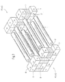
- roller 1 In the right part of the image, the front end one end of the roller 1 is still shown.
- the roller 1 is provided with a shaft journal 2, which receives a rolling bearing 3 for the roller 1.
- a motor 4 for driving the roller.
- the rectangular housing is made of two parts, part 5a and part 5b.
- This intermediate piece 7 is shown in the figure 1 below the housing 5 and above and laterally of the housing 5 only indicated.
- the intermediate piece 7 is non-positively connected to the housing 5 or 5a and 5b on a parallel pad 8, for example by welding. Due to this simple to produce and stackable - here box-shaped design - it is possible to construct a plurality of motor units in the desired dimensions arbitrarily one above the other and next to each other, so that overall results in a supporting stationary support A of the components within the machine. This can even form a stable Stung S of the machine or complement it in a convenient way. In FIG. 1 , the formed or already existing parts of the chair are marked with the position S.
Landscapes
- Engineering & Computer Science (AREA)
- General Engineering & Computer Science (AREA)
- Mechanical Engineering (AREA)
- Replacement Of Web Rolls (AREA)
- Paper (AREA)
- Brushes (AREA)
- Valve Device For Special Equipments (AREA)
- Vehicle Body Suspensions (AREA)
- Registering, Tensioning, Guiding Webs, And Rollers Therefor (AREA)
- Rolls And Other Rotary Bodies (AREA)
- Motor Or Generator Cooling System (AREA)
Claims (11)
- Dispositif d'entraînement pour des pièces tournantes, comme des rouleaux ou des cylindres d'une machine pour la fabrication et/ou le traitement d'une bande de matière, en particulier de papier ou de carton, dans lequela) les pièces tournantes (1) présentent respectivement des tourillons (2) à au moins une de leurs extrémité frontales,b) les tourillons frontaux (2) comportent chacun un moteur d'entraînement propre (4),c) la pièce respective (1) et le moteur d'entraînement (4) sont supportés localement en commun,d) il est prévu un boîtier (5), qui entoure aussi bien le moteur d'entraînement (4) que le palier (3) de la pièce respective (1),
caractérisé en ce quee) le boîtier respectif (5) présente une section transversale s'étendant sur toute sa longueur avec au moins une surface de raccordement (8), etf) le boîtier respectif (5) est réalisé de façon à pouvoir être construit en module pour le support local (A) en commun avec au moins un autre boîtier (5) et avec au moins une pièce intermédiaire (7) entre les surfaces de raccordement (8) des boîtiers respectifs (5). - Dispositif d'entraînement selon la revendication 1, caractérisé en ce que la section transversale du boîtier respectif (5) est de forme polygonale.
- Dispositif d'entraînement selon la revendication 1 ou 2, caractérisé en ce que la pièce intermédiaire (7) présente une forme correspondant à celle du boîtier (5).
- Dispositif d'entraînement selon une ou plusieurs des revendications 1 à 3, caractérisé en ce que chaque boîtier (5) et chaque pièce intermédiaire (7) est en forme de parallélépipède droit, de prisme ou de parallélépipède oblique et est composé d'une matière d'acier.
- Dispositif d'entraînement selon une ou plusieurs des revendications précédentes, caractérisé en ce que le boîtier respectif (5) est pourvu de perçages (6) pour le passage d'un fluide de refroidissement.
- Dispositif d'entraînement selon une ou plusieurs des revendications précédentes, caractérisé en ce que chaque boîtier (5) et chaque pièce intermédiaire (7) présente une dimension qui correspond approximativement au rapport longueur:largeur ∼ hauteur:largeur = 1:2 à 1:3, pour lequel on peut choisir différentes grandeurs de construction.
- Dispositif d'entraînement selon une ou plusieurs des revendications précédentes, caractérisé en ce que le moteur d'entraînement (4) ainsi qu'un palier (3) pour la pièce à entraîner (1) sont installés dans le boîtier respectif (5), dans lequel le moteur d'entraînement est disposé à l'extrémité extérieure du tourillon (2).
- Dispositif d'entraînement selon une ou plusieurs des revendications précédentes, caractérisé en ce que le boîtier respectif (5) et la pièce intermédiaire respective (7) sont reliés l'un à l'autre en complémentarité de force dans la région de leur au moins une surface de raccordement (8).
- Dispositif d'entraînement selon une ou plusieurs des revendications précédentes, caractérisé en ce que le boîtier respectif (5) est divisé et se compose des parties (5a et 5b).
- Dispositif d'entraînement selon une ou plusieurs des revendications 1 à 9, caractérisé en ce que le support local de forme modulaire peut être intégré dans un appui existant (S) de la machine pour la fabrication et/ou le traitement d'une bande de matière en défilement, ou forme lui-même cet appui (S).
- Dispositif d'entraînement selon une ou plusieurs des revendications précédentes, caractérisé en ce que le moteur d'entraînement électrique (4) est un moteur à emboîtement, asynchrone, à courant continu et à arbre creux, connu en soi.
Applications Claiming Priority (5)
| Application Number | Priority Date | Filing Date | Title |
|---|---|---|---|
| DE10025316 | 2000-05-22 | ||
| DE2000125316 DE10025316A1 (de) | 2000-05-22 | 2000-05-22 | Antriebseinheit |
| DE2000135578 DE10035578B4 (de) | 2000-07-21 | 2000-07-21 | Antriebseinheit |
| DE10035578 | 2000-07-21 | ||
| EP01110935A EP1158188B1 (fr) | 2000-05-22 | 2001-05-05 | Dispositif d'entraînement |
Related Parent Applications (1)
| Application Number | Title | Priority Date | Filing Date |
|---|---|---|---|
| EP01110935A Division EP1158188B1 (fr) | 2000-05-22 | 2001-05-05 | Dispositif d'entraînement |
Publications (3)
| Publication Number | Publication Date |
|---|---|
| EP1437516A2 EP1437516A2 (fr) | 2004-07-14 |
| EP1437516A3 EP1437516A3 (fr) | 2005-11-16 |
| EP1437516B1 true EP1437516B1 (fr) | 2007-11-07 |
Family
ID=26005783
Family Applications (2)
| Application Number | Title | Priority Date | Filing Date |
|---|---|---|---|
| EP04100531A Expired - Lifetime EP1437516B1 (fr) | 2000-05-22 | 2001-05-05 | Dispositif d'entraînement |
| EP01110935A Expired - Lifetime EP1158188B1 (fr) | 2000-05-22 | 2001-05-05 | Dispositif d'entraînement |
Family Applications After (1)
| Application Number | Title | Priority Date | Filing Date |
|---|---|---|---|
| EP01110935A Expired - Lifetime EP1158188B1 (fr) | 2000-05-22 | 2001-05-05 | Dispositif d'entraînement |
Country Status (3)
| Country | Link |
|---|---|
| EP (2) | EP1437516B1 (fr) |
| AT (2) | ATE338893T1 (fr) |
| DE (2) | DE50113243D1 (fr) |
Families Citing this family (12)
| Publication number | Priority date | Publication date | Assignee | Title |
|---|---|---|---|---|
| AU2003229565A1 (en) * | 2002-03-24 | 2003-10-08 | Vomag Gmbh | Device for supporting a shaft |
| DE102004001467A1 (de) * | 2003-03-19 | 2004-10-21 | Voith Paper Patent Gmbh | Maschine oder Maschinenabschnitt mit wenigstens einem vorzugsweise als Synchronmotor oder/und Aufsteckmotor ausgeführten und zum Direktantrieb eines Wickelkerns einer Wickelrolle oder zum Direktantrieb einer sonstigen Drehkomponente dienenden Elektromotor, insbesondere zur Verwendung in der Papierindustrie, und sich hierauf beziehendes Umbauverfahren |
| EP1787929A1 (fr) * | 2003-03-19 | 2007-05-23 | Voith Patent GmbH | Machine ou section de machine dotée d'au moins un électromoteur développé de préférence en tant que moteur synchrone et/ou à emboîtement et destiné à l'engrenage direct d'un axe d'enroulement d'une bobine d'enroulement ou à l'engrenage direct d'un autre composant de rotation, en particulier destiné à l'utilisation dans l'industrie du papier, et son procédé de transformation |
| DE10339733A1 (de) * | 2003-08-28 | 2004-11-25 | Siemens Ag | Antrieb zum rotatorischen Betrieb einer Walze |
| DE102004013781A1 (de) * | 2004-03-20 | 2005-10-06 | Voith Paper Patent Gmbh | Seilantriebsvorrichtung |
| DE102004059402A1 (de) * | 2004-12-09 | 2006-06-14 | Voith Paper Patent Gmbh | Modulare Maschine zur Herstellung oder/und Behandlung oder/und Handhabung einer laufenden Materialbahn insbesondere aus Papier oder Karton |
| DE102005000116A1 (de) * | 2005-09-14 | 2007-03-15 | Voith Patent Gmbh | Wickelmaschine zum Aufwickeln einer Materialbahn |
| SI1979536T1 (sl) * | 2006-01-25 | 2017-07-31 | Georgia-Pacific Consumer Products Lp | Stroj za izdelavo traku vlaknatega materiala |
| DE102006011632A1 (de) * | 2006-03-14 | 2007-09-20 | Voith Patent Gmbh | Antriebsbaugruppe zum Antreiben einer Walze |
| DE102009000745A1 (de) * | 2009-02-10 | 2010-08-12 | Voith Patent Gmbh | Antriebseinheit |
| DE102009003747A1 (de) * | 2009-04-06 | 2010-10-07 | As-Antriebstechnik Und Service Gmbh | Drehmomentstütze |
| IT202100012893A1 (it) * | 2021-05-19 | 2022-11-19 | V Project S R L | Macchina per la macinazione di prodotti alimentari |
Family Cites Families (6)
| Publication number | Priority date | Publication date | Assignee | Title |
|---|---|---|---|---|
| US1909792A (en) * | 1932-07-28 | 1933-05-16 | Milton T Weston | Variable speed drive |
| CH587690A5 (fr) * | 1975-01-29 | 1977-05-13 | Escher Wyss Ag | |
| DE3409738A1 (de) * | 1984-03-15 | 1985-09-26 | Mannesmann AG, 4000 Düsseldorf | Transporteinheit fuer langgestrecktes, metallisches heissgut |
| DE8703410U1 (de) * | 1987-03-06 | 1987-05-21 | J.M. Voith Gmbh, 7920 Heidenheim | Trockenzylinder od.dgl. einer Papier-, Karton- oder Streichmaschine |
| FI80304C (fi) * | 1989-01-23 | 1990-05-10 | Katsa Oy | Uppstaellning foer regleringsvaexel. |
| FI950176A0 (fi) * | 1995-01-16 | 1995-01-16 | Tasowheel Oy | Anordning foer spelfri ledning och maetning av till en ventil ledd roerelse |
-
2001
- 2001-05-05 EP EP04100531A patent/EP1437516B1/fr not_active Expired - Lifetime
- 2001-05-05 DE DE50113243T patent/DE50113243D1/de not_active Expired - Fee Related
- 2001-05-05 AT AT01110935T patent/ATE338893T1/de not_active IP Right Cessation
- 2001-05-05 EP EP01110935A patent/EP1158188B1/fr not_active Expired - Lifetime
- 2001-05-05 DE DE50110919T patent/DE50110919D1/de not_active Expired - Fee Related
- 2001-05-05 AT AT04100531T patent/ATE377715T1/de not_active IP Right Cessation
Also Published As
| Publication number | Publication date |
|---|---|
| EP1158188B1 (fr) | 2006-09-06 |
| EP1437516A2 (fr) | 2004-07-14 |
| DE50113243D1 (de) | 2007-12-20 |
| ATE377715T1 (de) | 2007-11-15 |
| ATE338893T1 (de) | 2006-09-15 |
| EP1158188A1 (fr) | 2001-11-28 |
| DE50110919D1 (de) | 2006-10-19 |
| EP1437516A3 (fr) | 2005-11-16 |
Similar Documents
| Publication | Publication Date | Title |
|---|---|---|
| EP0741020B2 (fr) | Machine d'impression rotative comprenant un appareil de pliage à assemblage libre | |
| EP0741019B2 (fr) | Appareil de pliage entraíné individuellement pour une machine d'impression rotative | |
| EP1437516B1 (fr) | Dispositif d'entraînement | |
| DE69408648T2 (de) | Einadriges Blockwalzwerk | |
| DE4225380A1 (de) | Hydrostatisches Aggregat mit einer Hauptpumpe und einer Nebenpumpe | |
| EP0738591A1 (fr) | Cylindre de transfert avec une unité d'entraînement électrique | |
| DE202019103771U1 (de) | Doppelgetriebe, insbesondere für einen elektromotorischen Antriebsstrang, mit einer Stützstruktur sowie dazugehörige Lagerbrille | |
| DE10025316A1 (de) | Antriebseinheit | |
| DE19530283A1 (de) | Übertragungszylinder mit elektromotorischer Antriebseinheit | |
| DE69705221T2 (de) | Metallplattenbiegevorrichtung mit offsetdruckrollen | |
| DE2119389A1 (de) | Baukastensystem für den Aufbau beliebiger Ständeranordnungen von Walzenmaschinen, insbesondere Kalandern | |
| DE3644628A1 (de) | Rollenmaschine zum kalten biegen von profilen | |
| DE20023897U1 (de) | Antriebseinheit | |
| DE3517975C2 (fr) | ||
| DE69300944T2 (de) | Verfahren und Vorrichtung zum Herstellen von einzelnen runden Stangen im warmen Zustand aus warmen Mehrfachelementen. | |
| DE69402980T2 (de) | Trommelstruktur für einen sterilisator | |
| DE69814908T2 (de) | Karussellwickelrolle | |
| DE3231590A1 (de) | Mechanische antriebsvorrichtung in der trockenpartie einer papiermaschine | |
| DE19616791A1 (de) | Walzblock zum Walzen von Draht, Stäben, Rohren oder flachem metallischem Walzgut | |
| DE69224884T2 (de) | Richtmaschine für Balken | |
| DE1602193A1 (de) | Walzenwechselvorrichtung an einem kombinierten Horizontal- und Vertikalgeruest | |
| DE1563007A1 (de) | Zweipoliger Induktor fuer elektrische Maschinen | |
| DE2833456A1 (de) | Walzstrasse zum streckreduzieren von rohren | |
| WO2001015875A1 (fr) | Machine pour couper en travers des bandes de materiau | |
| DE2704684A1 (de) | Richtmaschine zum richten von blechen und flachmaterialien |
Legal Events
| Date | Code | Title | Description |
|---|---|---|---|
| PUAI | Public reference made under article 153(3) epc to a published international application that has entered the european phase |
Free format text: ORIGINAL CODE: 0009012 |
|
| AC | Divisional application: reference to earlier application |
Ref document number: 1158188 Country of ref document: EP Kind code of ref document: P |
|
| AK | Designated contracting states |
Kind code of ref document: A2 Designated state(s): AT DE FI SE |
|
| PUAL | Search report despatched |
Free format text: ORIGINAL CODE: 0009013 |
|
| AK | Designated contracting states |
Kind code of ref document: A3 Designated state(s): AT DE FI SE |
|
| 17P | Request for examination filed |
Effective date: 20060516 |
|
| AKX | Designation fees paid |
Designated state(s): AT DE FI SE |
|
| RAP1 | Party data changed (applicant data changed or rights of an application transferred) |
Owner name: VOITH PATENT GMBH |
|
| GRAP | Despatch of communication of intention to grant a patent |
Free format text: ORIGINAL CODE: EPIDOSNIGR1 |
|
| GRAS | Grant fee paid |
Free format text: ORIGINAL CODE: EPIDOSNIGR3 |
|
| GRAA | (expected) grant |
Free format text: ORIGINAL CODE: 0009210 |
|
| AC | Divisional application: reference to earlier application |
Ref document number: 1158188 Country of ref document: EP Kind code of ref document: P |
|
| AK | Designated contracting states |
Kind code of ref document: B1 Designated state(s): AT DE FI SE |
|
| REF | Corresponds to: |
Ref document number: 50113243 Country of ref document: DE Date of ref document: 20071220 Kind code of ref document: P |
|
| REG | Reference to a national code |
Ref country code: SE Ref legal event code: TRGR |
|
| PLBE | No opposition filed within time limit |
Free format text: ORIGINAL CODE: 0009261 |
|
| STAA | Information on the status of an ep patent application or granted ep patent |
Free format text: STATUS: NO OPPOSITION FILED WITHIN TIME LIMIT |
|
| 26N | No opposition filed |
Effective date: 20080808 |
|
| PGFP | Annual fee paid to national office [announced via postgrant information from national office to epo] |
Ref country code: AT Payment date: 20090515 Year of fee payment: 9 Ref country code: DE Payment date: 20090525 Year of fee payment: 9 Ref country code: FI Payment date: 20090515 Year of fee payment: 9 Ref country code: SE Payment date: 20090514 Year of fee payment: 9 |
|
| PG25 | Lapsed in a contracting state [announced via postgrant information from national office to epo] |
Ref country code: AT Free format text: LAPSE BECAUSE OF NON-PAYMENT OF DUE FEES Effective date: 20100505 Ref country code: FI Free format text: LAPSE BECAUSE OF NON-PAYMENT OF DUE FEES Effective date: 20100505 |
|
| EUG | Se: european patent has lapsed | ||
| PG25 | Lapsed in a contracting state [announced via postgrant information from national office to epo] |
Ref country code: SE Free format text: LAPSE BECAUSE OF NON-PAYMENT OF DUE FEES Effective date: 20100506 |
|
| PG25 | Lapsed in a contracting state [announced via postgrant information from national office to epo] |
Ref country code: DE Free format text: LAPSE BECAUSE OF NON-PAYMENT OF DUE FEES Effective date: 20101201 |