EP1437757A1 - Tube a rayons x et son procede de fabrication - Google Patents
Tube a rayons x et son procede de fabrication Download PDFInfo
- Publication number
- EP1437757A1 EP1437757A1 EP02802013A EP02802013A EP1437757A1 EP 1437757 A1 EP1437757 A1 EP 1437757A1 EP 02802013 A EP02802013 A EP 02802013A EP 02802013 A EP02802013 A EP 02802013A EP 1437757 A1 EP1437757 A1 EP 1437757A1
- Authority
- EP
- European Patent Office
- Prior art keywords
- metal tube
- valve
- target
- inner cylinder
- cylinder portion
- Prior art date
- Legal status (The legal status is an assumption and is not a legal conclusion. Google has not performed a legal analysis and makes no representation as to the accuracy of the status listed.)
- Granted
Links
Images




Classifications
-
- H—ELECTRICITY
- H01—ELECTRIC ELEMENTS
- H01J—ELECTRIC DISCHARGE TUBES OR DISCHARGE LAMPS
- H01J35/00—X-ray tubes
- H01J35/02—Details
- H01J35/16—Vessels; Containers; Shields associated therewith
Definitions
- the present invention relates to an X-ray tube and a method for making the X-ray tube, and particularly to a micro-focus X-ray tube in which an X-ray focus point can be remarkably finely set, and a method for making the X-ray tube.
- An X-ray tube outputs X-rays by inpinging electrons on a target, and conventionally has been utilized as an X-ray generator such as an X-ray inspection apparatus or the like which is used for nondestructive inspection, non-contact inspection or the like.
- an X-ray generator such as an X-ray inspection apparatus or the like which is used for nondestructive inspection, non-contact inspection or the like.
- X-ray tube for a sample of Such X-ray tube, one disclosed in Japanese Unexamined Examined Utility Model Application No. H03-110753 is well known.
- the X-ray tube described in this publication has a vacuum envelope molded insulating material such as glass or the like in a substantially cylindrical shape. Both end portions of the vacuum envelope are inwardly folded over the overall peripheries thereof, and thus inner cylinder portions extending to the inside of the envelope are formed at both ends of the vacuum envelope.
- An electron generating unit containing a cathode filament, a focus electrode, etc., are fixed in one inner cylinder portion. Furthermore, a metal tube is fuse-bonded to the other folded portion. A target supporter for supporting a target is fixed to the metal tube. Accordingly, the electron generating unit and the target oppose each other.
- the present invention has an object to provide an X-ray tube in which respective components are fabricated accurately and the X-ray focus point can be set to an extremely small point, and a method for making an X-ray tube which can easily make an X-ray tube in which the X-ray focus point can be set to an extremely small point while remarkably keeping the dimension accuracy and the fabrication accuracy in the making process.
- an X-ray tube is an X-ray tube for impinging electrons emitted from an electron generating unit on a target and outputting X-rays, comprising an envelope main body having an accommodation portion for accommodating the electron generating unit; an insulating valve joined to the envelope at one end side thereof and having an inner cylinder portion extending inwardly at the other end side thereof, a metal tube having an extension fuse bonded to the inner cylinder portion on the outer periphery of one end side thereof and projecting outwardly from the valve through the inner cylinder portion at the other end side thereof, and a target supporter supporting a target at one end side thereof, inserted through the metal tube at the other side thereof and fuse-bonded to the end portion of the metal tube.
- the X-ray tube impinging electrons emitted from an electron generating unit on a target to output X-rays. Therefore, the X-ray tube comprises of an electron generating unit containing a cathode for generating electrons, etc., a target as an anode and a target supporter for supporting the target. Furthermore, the X-ray tube is provided with an envelope main body and a valve. The envelope main body and the valve constitute the vacuum envelope accommodating the electron generating unit, the target, etc.
- the envelope main body has an accommodation portion for accommodating the electron generating unit.
- the valve is designed in a substantially cylindrical shape by insulating material such as glass, ceramic or the like, and one end side thereof is joined to the envelope main body.
- An inner cylinder portion extending inwardly is provided at the other end portion of the valve. That is, the other end portion of the valve is folded inwardly over the overall periphery so that a hole portion is formed at the center portion.
- a metal tube for fixing the target supporter is secured to the valve.
- the metal tube is provided at one end side thereof with an extension portion which can abut against the inner cylinder portion of the valve. That is, one end portion of the metal tube is folded outwardly over the overall periphery and a cylinder portion having substantially the same diameter as the inner cylinder portion of the valve is formed on the outer periphery of one end side of the metal tube. Furthermore, the other end side of the metal tube can be inserted through the inner cylinder portion of the valve. In addition, the other end side of the target supporter for supporting the target can be inserted through the metal tube.
- the X-ray tube comprising the above components according to the present invention is made according to the following procedure.
- the metal tube is secured to the valve previously.
- the metal tube is secured to the valve, (the end face of) the inner cylinder portion and (the end face of) the extension portion of the metal tube are fuse-bonded to each other under a state where the metal tube is projected from the inner cylinder portion to the outside of the valve.
- the metal tube can be reliably positioned in the valve, and thus both can be fuse-bonded to each other accurately.
- the target supporter is welded to the end portion of the metal tube projecting from the valve while the other end of the target supporter (the end portion of the target supporter at which the target is not supported) is inserted into the metal tube fixed to the valve.
- the target supporter is slid relatively to the metal tube while a jig, an optical position sensor or the like is used, whereby the securing position of the target can be determined accurately.
- the work of welding the target supporter to the metal tube can be easily performed from the outside of the valve, and thus the target supporter and the metal tube can be firmly fixed to each other accurately.
- the inside of the vacuum envelope comprising the envelope main body and the valve can be kept air-tight.
- the respective components can be fabricated while positioned with extremely high accuracy, and the positional relationship between the electron generating unit and the target is determined accurately. Accordingly, according to the X-ray tube, the X-ray focus point can be set to an extremely small point.
- an x-ray tube for impinging electrons emitted from an electron generating unit accommodated in an envelope main body on a target supported by a target supporter to output X-rays by using a valve having an inwardly-extending inner cylinder portion at the opposite side to the side thereof to be joined to the envelope main body and a metal tube provided with an extension portion abutting against the inner cylinder portion of the valve on the outer periphery thereof and is insertable through the inner cylinder portion, the end face of the inner cylinder portion and the extension portion of the metal tube are fuse-bonded to each other while the metal tube is projected from the inner cylinder portion to the outside of the valve, the target supporter is inserted into the metal tube, and the target supporter is welded to the end portion of the metal tube projecting from the valve.
- the respective components can be fabricated while remarkably keeping the dimension accuracy and the fabrication accuracy in the manufacturing process. Accordingly, when the X-ray tube making method described above is used, there can be easily made an X-ray tube in which the X-ray focus point can be set to an extremely small point.
- the target supporter when the target supporter is welded to the end portion of the metal tube, the target supporter is preferably positioned to the metal tube by using a jig. Furthermore, when the target supporter is welded to the end portion of the metal tube, the target supporter may be positioned to the metal tube by using position detecting means.
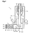
- Fig. 1 is a cross-sectional view showing a preferred embodiment of an X-ray tube according to the present invention.
- the X-ray tube 1 shown in Fig. 1 is suitably used as an X-ray generating source of an X-ray inspection apparatus, for example, and it comprises of a vacuum envelope 2, an electron generating unit (electron gun) 3, and a target T.
- the electron generating unit 3 has a cathode C which is a porous tungsten or the like, impregnated with BaO or the like.
- the target T is a laminated X-ray generating films formed of tungsten or the like through a protection layer on a carbon layer.
- the vacuum envelope 2 mainly comprises an envelope main body 4 and a valve 10.
- the envelope main body 4 comprises a body portion 5 in which the target T serving as an anode is accommodated, and an electron gun accommodating portion 6 in which the electron generating unit 3 serving as a cathode is accommodated.
- the body portion 5 is formed of metal or the like in a cylindrical shape, and has an inner space 5a.
- a flange portion 5b fixed to a housing or the like of the X-ray inspection apparatus (not shown) is provided on the outer periphery of the body portion 5.
- a lid plate 7 having an output window 7a is fixed to the lower portion of the body portion 5 in Fig. 1, and one end side of the inner space 5a is closed by the lid plate 7.
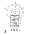
- the electron gun accommodating portion 6 is formed in a cylindrical shape so as to have a substantially rectangular cross-section as shown in Fig. 2, and connected (fixed) to the lower portion of the side portion of the body portion 5. As shown in Fig. 1, the axial center of the body portion 5 and the axial center of the electron gun accommodating unit 6 are substantially orthogonal to each other, and the inside of the electron gun accommodating portion 6 intercommunicates with the internal space 5a of the body portion 5 through an aperture 6a.
- the electron generating unit 3 accommodated in the electron gun accommodating portion 6 will be described.
- the electron generating unit 3 contains a cathode C, a heater 30, a first grid electrode 31 and a second grid electrode 32.
- the cathode C, the heater 30, the first grid electrode 31 and the second grid electrode 32 are secured to a stem board 34 through plural (eight in this embodiment) pins 33a to 33h extending in parallel.
- the cathode C is secured to the pin 33a (see Fig. 2) fixed to the stem board 34, and supplied with electric power from the outside through the pin 33a.
- the heater 30 is secured to the pins 33b and 33c (see Fig. 2) fixed to the stem board 34, and supplied with electric power from the outside through the pins 33b and 33c.
- the first grid electrode 31 is secured to the pins 33d, 33e, 33f and 33g fixed to the stem board 34, and supplied with electric power from the outside through these pins 33d to 33g.
- the second grid electrode 32 is secured to the pin 33h fixed to the stem board 34, and supplied with electric power from the outside through the pin 33h.
- the electron generating unit 3 in which the cathode C, etc., are unified to the stem board 34 is inserted from the end portion at the opposite side to the aperture 6a into the electron gun accommodating portion 6, and the stem board 34 is fixed to the end portion of the electron gun accommodating portion 6.
- the valve 10 constituting the vacuum envelope 2 in combination with the envelope main body 4 is formed of insulating material such as glass, ceramic or the like in a substantially cylindrical shape. As shown in Fig. 1, a ring member 8 formed of metal or the like is fuse-bonded to one end side (the lower end side in Fig. 1) of the valve 10. The ring member 8 is joined (welded) to the body portion 5 constituting the envelope main body 4. As described above, one end side of the valve 10 is joined to the envelope main body 4.
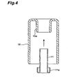
- an inner cylinder portion 10a having a cylindrical shape extending inwardly is provided on the other end side (the upper end side in Fig. 1 and Fig. 4) of the valve 10. That is, the other end portion (upper end portion) of the valve 10 is folded inwardly across the overall periphery thereof so that a hole portion is sectionally formed at the center portion, whereby the other end side of the valve 10 is opened to the outside through the inside of the inner cylinder portion 10a.
- the metal tube 11 for supporting the target T in the body portion 5 is secured to the inner cylinder portion 10a of the valve 10.
- the metal tube 11 basically has an outer diameter smaller than the inner diameter of the inner cylinder portion 10a of the valve 10.
- the metal tube 11 also has an extension portion 11a on the outer periphery at one end side thereof (the lower end side in Fig. 4). That is, the one end portion of the metal tube 11 is outwardly folded over the overall periphery thereof, and a cylindrical portion (outer cylinder portion) having substantially the same diameter as the inner cylinder portion 10a of the valve 10 is formed on the outer periphery at the one end side of the metal tube 11.
- the other end side (the upper end side in Fig. 4) of the metal tube 11 can be inserted into the inner cylinder portion 10a of the valve 10.
- the target supporter 12 is formed of copper material or the like in a rod shape, and a slant surface 12a (see Fig. 1) which is inclined so as to be far from the electron generating unit 3 as approaching from the valve 10 side to the body portion 5 side (in Fig. 1, from the upper side to the lower side) is provided at one end side (the lower end side in Fig. 1) of the target supporter 12.
- the target T is embedded at the end portion of the target supporter 12 so that the surface thereof is aligned with the slant surface 12a.
- the other end portion (the upper end portion in Fig. 1) of the target supporter 12 is welded to the end portion of the metal tube 11 projecting from the valve 10, whereby the target supporter 12 extends substantially in parallel to the axial centers of the valve 10 and the body portion 5, and also it is substantially orthogonal to the travel direction of electrons from the electron generating unit 3. Accordingly, when electrons emitted from the electron generating unit (electron gun) 3 impinge against the target T in the vacuum envelope 2, an X-ray is output from the surface of the target T in a direction substantially orthogonal to the travel direction of the electrons. The X-ray is discharged to the outside through the output window 7a covering the open end (the end portion at the opposite side to the valve 10 side) of the body portion 5.
- a cover electrode 14 is mounted so as to cover the fuse-bonded portion between the inner cylinder portion 10a and the extension portion 11a of the metal tube 11 in the valve 10.
- the method for manufacturing the X-ray tube 1 constructed as described above that is, the X-ray tube making method according to the present invention will be described.
- the body portion 5 and the electron gun accommodating portion 6 are joined to each other to fabricate the outer envelope main body 4 at a predetermined stage, and also the metal tube 11 is secured to the valve 10 previously.
- the metal tube 11 is secured to the valve 10
- the end face of the inner cylinder portion 10a and the end face of the extension portion 11a of the metal tube 11 are fuse-bonded to each other under a state where the metal tube 11 is projected from the inner cylinder portion 10a to the outside of the valve 10.
- valve 10 At this time, the end portion of the valve 10 at the opposite side to the inner cylinder portion 10a is perfectly opened (see Fig. 4), and thus the metal tube 11 can be easily and accurately positioned in the valve 10. Accordingly, the valve 10 and the metal tube 11 can be fuse-bonded to each other while they are positioned to each other accurately.
- the respective components are assembled according to the procedure shown in Fig. 5. That is, first, the valve 10 securing the metal tube 11 and the envelope main body 4 are joined to each other (S10). In this case, the ring member 8 which is fuse-bonded to the valve 10 previously is welded to the envelope main body 4 (body portion 5). Subsequently, the valve 10 is joined to the envelope main body 4, and the other end of the target supporter 12 (the end portion of the target supporter 12 at which the target T is not supported) is inserted into the metal tube 11 fixed to the valve 10, and under this state, the target supporter 12 is positioned to the valve 10. Furthermore, the target supporter 12 is welded to the end portion of the metal tube 11 projecting from the valve 10 (S12).
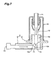
- jigs as shown in Fig. 6 and Fig. 7 are preferably used.
- a jig 60 shown in Fig. 6 can be engangedly fitted in the inner space 5a of the body portion constituting the envelope main body 4 from the open end at the opposite side to the valve 10.
- the jig 60 is fitted in the inner space 5a of the body portion 5
- the jig 60 is fitted to the end portion of the target supporter 12 inserted into the metal tube 11 so that the target T is located at a predetermined mount place. That is, the jig 60 has a slant surface 61 abutting against the slant surface 12a of the target supporter 12 and a regulating surface 62 abutting against the end face 12b of the target supporter 12.
- a jig 70 shown in Fig. 7 can be inserted into the inner space 5a of the body portion 5 constituting the envelope main body 4 from the open end of the electron gun accommodating portion 6.
- the jig 70 is inserted into the inner space 5a of the body portion 5 so as to be in parallel to the axial center of the electron gun accommodating portion 6, the jig 70 is fitted to the end portion of the target supporter 12 inserted into the metal tube 11 so that the target T is located at a predetermined mount place. That is, the jig 70 has a slant surface 71 abutting against the slant surface 12a of the target supporter 12 and a regulating surface 72 abutting against the end face 12b of the target supporter 12.
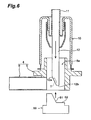
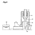
- an optical position sensor 80 position detecting means as shown in Fig. 8 and Fig. 9 may be used.
- the envelope main body 4 and the valve 10 are mounted on the horizontal plane H so that the axial center of the valve 10 and the metal tube 11 is located vertically.
- measurement light is irradiated from the optical position sensor 80 to the end face 12c of the target supporter 12 at the metal tube 11 side and the horizontal plane H. That is, in this case, the target supporter 12 is slid with respect to the metal tube 11 so that the target T is located at a predetermined mount place while detecting the distance between the horizontal plane H and the end face 12c of the target supporter 12.
- the optical position sensor 80 is positioned on the horizontal plane H, the measurement light is irradiated from the optical position sensor 80 into the inner space 5a of the body portion 5 through the electron gun accommodating portion 6. And, in this case, the target supporter 12 is slid with respect to the metal tube 11 so that the target T is located at a predetermined mount place while detecting the end face 12b at the target T side of the target supporter 12.
- the mount position of the target T can be determined accurately by using the position detecting means such as the jigs 60 and 70, the optical position sensor 80 or the like and sliding the target supporter 12 relatively to the metal tube 11.
- the welding work is carried out after the target supporter 12 is accurately positioned to the valve 10 as described above.
- the work of welding the target supporter 12 to the metal tube 11 can be easily carried out from the outside of the valve 10. Accordingly, the target supporter 12 and the metal tube 11 can be firmly fixed to each other accurately, and also the inside of the vacuum envelope 2 comprising the envelope main body 4 and the valve 10 can be reliably kept air-tight.
- the cover electrode 14 may be mounted in the valve 10 or fixed to the target supporter 12 before the target supporter 12 is welded to the metal tube 11.
- the electron generating unit 3 is inserted into the electron gun accommodating portion 6, and the stem board 34 is fixed to the electron gun accommodating portion 6 (S14) so that the envelope is reliably kept air-tight. Furthermore, the lid plate 7 having the output window 7a formed therein is fixed to the body portion 5 of the envelope main body 4 so that the envelope can be reliably kept air-tight (S16), thereby completing the X-ray tube 1.
- the respective components can be fabricated while remarkably keeping the dimension accuracy and the fabrication accuracy in the making process. Accordingly, by using the X-ray tube making method, the positional relationship between the electron generating unit 3 and the target T can be set accurately. According to the X-ray tube 1 made by this method, the X-ray focus point can be set to an extremely small point.
- the making procedure of the X-ray tube 1 shown in Fig 5 is merely an example, and various modes can be used as the making procedure of the X-ray tube 1.
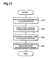
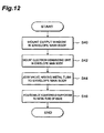
- Fig. 10 to Fig. 12 show other making procedures of the X-ray tube 1.
- the body portion 5 and the electron gun accommodating portion 6 are joined to each other to fabricate an envelope main body 4 at a predetermined stage, and also the metal tube 11 is secured to the valve 10 previously.
- the electron generating unit 3 is secured to the electron gun accommodating portion 6 of the envelope main body 4 (S20).
- the valve 10 securing the metal tube 11 is fixed to the envelope main body 4 (S22).
- the target supporter 12 is inserted into the metal tube 11 fixed to the valve 10, positioned and then welded to the metal tube 11 (S24).
- the electron gun accommodating portion 6 has been already closed by the stem board 34.
- the jig 60 shown in Fig. 6 is used or the optical position sensor 80 is used as shown in Fig. 8.
- the lid plate 7 having the output window 7a is fixed to the body portion 5 of the envelope main body 4 (S26), the X-ray tube 1 is completed.
- the electron generating unit 3 is secured to the electron gun accommodating portion 6 of the envelope main body 4 (S30). Subsequently, the lid plate 7 having the output window 7a is fixed to the body portion 5 of the envelope main body 4 (S32).
- the valve 10 fixed the metal tube 11 is fixed to the envelope main body 4 (S34).
- the target supporter 12 is welded to the metal tube 11. In this case, the inner space 5a of the body portion 5 has been already closed by the lid plate 7, and the electron gun accommodating portion 6 has been already closed by the stem board 34.
- the target supporter 12 is inserted from the outside of the valve 10 into the metal tube 11, and also the target supporter 12 is positioned while the optical position sensor 80 is used as shown in Fig. 8, whereby the X-ray tube 1 is completed.
- the lid plate 7 having the output window 7a is first fixed to the body portion 5 of the envelope main body 4 (S40). Subsequently, the electron generating unit 3 is secured to the electron gun accommodating portion 6 of the envelope main body 4 (S42). When the electron generating unit 3 is mounted to the electron gun accommodating portion 6, the valve 10 securing the metal tube 11 is fixed to the envelope main body 4 (S44). Thereafter, the target supporter 12 is welded to the metal tube 11 (S46). In this case, the inner space 5a of the body portion 5 has been already closed by the lid plate 7, and the electron gun accommodating portion 6 has been already closed by the stem board 34.
- the target supporter 12 is inserted into the metal tube 11 from the outside of the valve 10, and also the target supporter 12 is positioned while the optical position sensor 80 is used as shown in Fig. 8, whereby the X-ray tube 1 is completed.
- the X-ray tube and the X-ray tube making method according to the present invention are suitably used as a micro-focus X-ray tube which can set the X-ray focus point to an extremely small point, and the method for manufacturing the same.
Landscapes
- X-Ray Techniques (AREA)
- Manufacture Of Electron Tubes, Discharge Lamp Vessels, Lead-In Wires, And The Like (AREA)
Applications Claiming Priority (3)
| Application Number | Priority Date | Filing Date | Title |
|---|---|---|---|
| JP2001322577A JP4068332B2 (ja) | 2001-10-19 | 2001-10-19 | X線管、及び、x線管の製造方法 |
| JP2001322577 | 2001-10-19 | ||
| PCT/JP2002/010670 WO2003036676A1 (fr) | 2001-10-19 | 2002-10-15 | Tube a rayons x et son procede de fabrication |
Publications (3)
| Publication Number | Publication Date |
|---|---|
| EP1437757A1 true EP1437757A1 (fr) | 2004-07-14 |
| EP1437757A4 EP1437757A4 (fr) | 2006-08-02 |
| EP1437757B1 EP1437757B1 (fr) | 2011-05-18 |
Family
ID=19139603
Family Applications (1)
| Application Number | Title | Priority Date | Filing Date |
|---|---|---|---|
| EP02802013A Expired - Lifetime EP1437757B1 (fr) | 2001-10-19 | 2002-10-15 | Tube a rayons x et son procede de fabrication |
Country Status (6)
| Country | Link |
|---|---|
| US (1) | US7058161B2 (fr) |
| EP (1) | EP1437757B1 (fr) |
| JP (1) | JP4068332B2 (fr) |
| KR (1) | KR100848441B1 (fr) |
| CN (1) | CN1310278C (fr) |
| WO (1) | WO2003036676A1 (fr) |
Cited By (2)
| Publication number | Priority date | Publication date | Assignee | Title |
|---|---|---|---|---|
| WO2006070586A1 (fr) | 2004-12-27 | 2006-07-06 | Hamamatsu Photonics K.K. | Tube a rayons x et source de rayons x |
| US10825638B2 (en) | 2018-04-12 | 2020-11-03 | Hamamatsu Photonics K.K. | X-ray tube |
Families Citing this family (18)
| Publication number | Priority date | Publication date | Assignee | Title |
|---|---|---|---|---|
| DE102005043372B4 (de) * | 2005-09-12 | 2012-04-26 | Siemens Ag | Röntgenstrahler |
| JP4954525B2 (ja) * | 2005-10-07 | 2012-06-20 | 浜松ホトニクス株式会社 | X線管 |
| KR101289502B1 (ko) * | 2005-10-07 | 2013-07-24 | 하마마츠 포토닉스 가부시키가이샤 | X선관 및 비파괴 검사 장치 |
| JP4954526B2 (ja) * | 2005-10-07 | 2012-06-20 | 浜松ホトニクス株式会社 | X線管 |
| US9257257B2 (en) | 2006-06-30 | 2016-02-09 | Shimadzu Corporation | Electron beam control method, electron beam generating apparatus, apparatus using the same, and emitter |
| US8213575B2 (en) * | 2006-11-21 | 2012-07-03 | Shimadzu Corporation | X-ray generating apparatus |
| DE102008006620A1 (de) * | 2008-01-29 | 2009-08-06 | Smiths Heimann Gmbh | Röntgenstrahlerzeuger sowie dessen Verwendung in einem Röntgenuntersuchungs- oder Röntgenprüfgerät |
| JP5591048B2 (ja) * | 2010-09-30 | 2014-09-17 | キヤノン株式会社 | X線管の製造方法、及びx線管 |
| KR101089231B1 (ko) * | 2011-04-13 | 2011-12-02 | 테크밸리 주식회사 | X선관 |
| JP2013239317A (ja) * | 2012-05-15 | 2013-11-28 | Canon Inc | 放射線発生ターゲット、放射線発生装置および放射線撮影システム |
| JP5763032B2 (ja) * | 2012-10-02 | 2015-08-12 | 双葉電子工業株式会社 | X線管 |
| CN103681181B (zh) * | 2013-11-26 | 2016-04-06 | 无锡日联科技股份有限公司 | 用于微焦点x射线管的阴极电子枪 |
| JP2016173926A (ja) * | 2015-03-17 | 2016-09-29 | 東芝電子管デバイス株式会社 | X線管 |
| JP7103829B2 (ja) * | 2018-04-12 | 2022-07-20 | 浜松ホトニクス株式会社 | X線管 |
| JP7112235B2 (ja) | 2018-04-12 | 2022-08-03 | 浜松ホトニクス株式会社 | X線管 |
| JP7048396B2 (ja) | 2018-04-12 | 2022-04-05 | 浜松ホトニクス株式会社 | X線管 |
| WO2021095298A1 (fr) * | 2019-11-11 | 2021-05-20 | キヤノン電子管デバイス株式会社 | Tube à rayons x et procédé de fabrication de tube à rayons x |
| CN116978762B (zh) * | 2023-09-22 | 2023-11-24 | 上海超群检测科技股份有限公司 | 阳极组件的兜料式焊接方法 |
Family Cites Families (15)
| Publication number | Priority date | Publication date | Assignee | Title |
|---|---|---|---|---|
| BE417964A (fr) * | 1935-10-07 | |||
| JPS5725660A (en) | 1980-07-21 | 1982-02-10 | Toshiba Corp | X-ray tube |
| GB2089109B (en) | 1980-12-03 | 1985-05-15 | Machlett Lab Inc | X-rays targets and tubes |
| US4484069A (en) * | 1981-10-15 | 1984-11-20 | St. Regis Paper Company | Apparatus and method for sensing distance |
| IL71676A0 (en) | 1984-04-27 | 1984-12-31 | Israel State | X-ray tube |
| JPS6318757A (ja) | 1986-07-10 | 1988-01-26 | Mitsubishi Electric Corp | 記録情報処理装置 |
| JPS6318757U (fr) * | 1986-07-23 | 1988-02-06 | ||
| JPH03110753A (ja) | 1989-09-26 | 1991-05-10 | Iwasaki Electric Co Ltd | メタルハライドランプ始動装置 |
| JP3032271B2 (ja) * | 1990-10-12 | 2000-04-10 | 株式会社東芝 | 回転陽極型x線管 |
| JPH0729487A (ja) | 1993-07-12 | 1995-01-31 | Toshiba Corp | X線管の組立方法 |
| JP2713860B2 (ja) * | 1994-04-26 | 1998-02-16 | 浜松ホトニクス株式会社 | X線管装置 |
| DE19513291C2 (de) * | 1995-04-07 | 1998-11-12 | Siemens Ag | Röntgenröhre |
| JP3159663B2 (ja) * | 1997-03-07 | 2001-04-23 | 株式会社東芝 | 回転陽極型x線管の製造方法 |
| JP4574755B2 (ja) * | 1998-02-06 | 2010-11-04 | 浜松ホトニクス株式会社 | X線発生装置及び検査システム |
| JP4261691B2 (ja) * | 1999-07-13 | 2009-04-30 | 浜松ホトニクス株式会社 | X線管 |
-
2001
- 2001-10-19 JP JP2001322577A patent/JP4068332B2/ja not_active Expired - Lifetime
-
2002
- 2002-10-15 CN CNB028206398A patent/CN1310278C/zh not_active Expired - Lifetime
- 2002-10-15 EP EP02802013A patent/EP1437757B1/fr not_active Expired - Lifetime
- 2002-10-15 KR KR1020047005751A patent/KR100848441B1/ko not_active Expired - Lifetime
- 2002-10-15 US US10/492,818 patent/US7058161B2/en not_active Expired - Lifetime
- 2002-10-15 WO PCT/JP2002/010670 patent/WO2003036676A1/fr not_active Ceased
Cited By (4)
| Publication number | Priority date | Publication date | Assignee | Title |
|---|---|---|---|---|
| WO2006070586A1 (fr) | 2004-12-27 | 2006-07-06 | Hamamatsu Photonics K.K. | Tube a rayons x et source de rayons x |
| EP1833075A4 (fr) * | 2004-12-27 | 2009-02-25 | Hamamatsu Photonics Kk | Tube a rayons x et source de rayons x |
| US7773726B2 (en) | 2004-12-27 | 2010-08-10 | Hamamatsu Photonics K.K. | X-ray tube and X-ray source |
| US10825638B2 (en) | 2018-04-12 | 2020-11-03 | Hamamatsu Photonics K.K. | X-ray tube |
Also Published As
| Publication number | Publication date |
|---|---|
| JP2003132826A (ja) | 2003-05-09 |
| CN1572011A (zh) | 2005-01-26 |
| US7058161B2 (en) | 2006-06-06 |
| US20050058253A1 (en) | 2005-03-17 |
| KR20040045869A (ko) | 2004-06-02 |
| WO2003036676A1 (fr) | 2003-05-01 |
| EP1437757A4 (fr) | 2006-08-02 |
| JP4068332B2 (ja) | 2008-03-26 |
| CN1310278C (zh) | 2007-04-11 |
| EP1437757B1 (fr) | 2011-05-18 |
| KR100848441B1 (ko) | 2008-07-28 |
Similar Documents
| Publication | Publication Date | Title |
|---|---|---|
| EP1437757B1 (fr) | Tube a rayons x et son procede de fabrication | |
| EP1096543B1 (fr) | Tube a rayons x | |
| EP1596417A1 (fr) | Equipement a rayons x | |
| KR101237653B1 (ko) | X선관 및 이를 포함하는 x선원 | |
| WO2007105390A1 (fr) | Appareil de production de faisceau d'électrons | |
| US7340036B2 (en) | X-ray generator | |
| US7012261B2 (en) | Multipole lens, charged-particle beam instrument fitted with multipole lenses, and method of fabricating multipole lens | |
| TWI449074B (zh) | X-ray tube | |
| US7429740B2 (en) | Electric-magnetic field-generating element and assembling method for same | |
| JP4133508B2 (ja) | 多極子レンズの製造方法及び多極子レンズ並びに多極子レンズを備えた観察装置 | |
| US12444518B2 (en) | Energy beam irradiation device | |
| JPS58915Y2 (ja) | X線イメ−ジ管 | |
| JP4009082B2 (ja) | X線管 | |
| KR101089236B1 (ko) | X선관의 조립 프레임 | |
| JPH11307031A (ja) | 分析電子顕微鏡 | |
| JP5349265B2 (ja) | 静電多極子型の偏向器・レンズの製造方法および偏向器・レンズ | |
| JP2017059360A (ja) | X線計測装置、電子線源の交換方法、及び電子銃 | |
| JP2001160367A (ja) | X線管並びにその組立方法及び組立装置 |
Legal Events
| Date | Code | Title | Description |
|---|---|---|---|
| PUAI | Public reference made under article 153(3) epc to a published international application that has entered the european phase |
Free format text: ORIGINAL CODE: 0009012 |
|
| 17P | Request for examination filed |
Effective date: 20040419 |
|
| AK | Designated contracting states |
Kind code of ref document: A1 Designated state(s): AT BE BG CH CY CZ DE DK EE ES FI FR GB GR IE IT LI LU MC NL PT SE SK TR |
|
| AX | Request for extension of the european patent |
Extension state: AL LT LV MK RO SI |
|
| A4 | Supplementary search report drawn up and despatched |
Effective date: 20060630 |
|
| 17Q | First examination report despatched |
Effective date: 20071108 |
|
| GRAP | Despatch of communication of intention to grant a patent |
Free format text: ORIGINAL CODE: EPIDOSNIGR1 |
|
| GRAS | Grant fee paid |
Free format text: ORIGINAL CODE: EPIDOSNIGR3 |
|
| GRAA | (expected) grant |
Free format text: ORIGINAL CODE: 0009210 |
|
| AK | Designated contracting states |
Kind code of ref document: B1 Designated state(s): DE FR |
|
| REG | Reference to a national code |
Ref country code: DE Ref legal event code: R096 Ref document number: 60240088 Country of ref document: DE Effective date: 20110630 |
|
| PLBE | No opposition filed within time limit |
Free format text: ORIGINAL CODE: 0009261 |
|
| STAA | Information on the status of an ep patent application or granted ep patent |
Free format text: STATUS: NO OPPOSITION FILED WITHIN TIME LIMIT |
|
| 26N | No opposition filed |
Effective date: 20120221 |
|
| REG | Reference to a national code |
Ref country code: DE Ref legal event code: R097 Ref document number: 60240088 Country of ref document: DE Effective date: 20120221 |
|
| REG | Reference to a national code |
Ref country code: FR Ref legal event code: PLFP Year of fee payment: 15 |
|
| REG | Reference to a national code |
Ref country code: FR Ref legal event code: PLFP Year of fee payment: 16 |
|
| REG | Reference to a national code |
Ref country code: FR Ref legal event code: PLFP Year of fee payment: 17 |
|
| PGFP | Annual fee paid to national office [announced via postgrant information from national office to epo] |
Ref country code: FR Payment date: 20210913 Year of fee payment: 20 |
|
| PGFP | Annual fee paid to national office [announced via postgrant information from national office to epo] |
Ref country code: DE Payment date: 20210908 Year of fee payment: 20 |
|
| REG | Reference to a national code |
Ref country code: DE Ref legal event code: R071 Ref document number: 60240088 Country of ref document: DE |