EP1596417A1 - Equipement a rayons x - Google Patents
Equipement a rayons x Download PDFInfo
- Publication number
- EP1596417A1 EP1596417A1 EP04701122A EP04701122A EP1596417A1 EP 1596417 A1 EP1596417 A1 EP 1596417A1 EP 04701122 A EP04701122 A EP 04701122A EP 04701122 A EP04701122 A EP 04701122A EP 1596417 A1 EP1596417 A1 EP 1596417A1
- Authority
- EP
- European Patent Office
- Prior art keywords
- electron beam
- target
- ray apparatus
- magnet portion
- cathode
- Prior art date
- Legal status (The legal status is an assumption and is not a legal conclusion. Google has not performed a legal analysis and makes no representation as to the accuracy of the status listed.)
- Withdrawn
Links
- 238000010894 electron beam technology Methods 0.000 claims abstract description 62
- 239000010408 film Substances 0.000 description 8
- 238000003780 insertion Methods 0.000 description 8
- 230000037431 insertion Effects 0.000 description 8
- WFKWXMTUELFFGS-UHFFFAOYSA-N tungsten Chemical compound [W] WFKWXMTUELFFGS-UHFFFAOYSA-N 0.000 description 7
- 229910052721 tungsten Inorganic materials 0.000 description 7
- 239000010937 tungsten Substances 0.000 description 7
- 239000011521 glass Substances 0.000 description 6
- 230000005540 biological transmission Effects 0.000 description 5
- 230000004907 flux Effects 0.000 description 4
- 229910052790 beryllium Inorganic materials 0.000 description 2
- ATBAMAFKBVZNFJ-UHFFFAOYSA-N beryllium atom Chemical compound [Be] ATBAMAFKBVZNFJ-UHFFFAOYSA-N 0.000 description 2
- 230000006866 deterioration Effects 0.000 description 2
- 230000000694 effects Effects 0.000 description 2
- 238000009413 insulation Methods 0.000 description 2
- 239000000463 material Substances 0.000 description 2
- 229910052751 metal Inorganic materials 0.000 description 2
- 239000002184 metal Substances 0.000 description 2
- 238000012360 testing method Methods 0.000 description 2
- 238000003466 welding Methods 0.000 description 2
- 238000001816 cooling Methods 0.000 description 1
- 239000005343 cylinder glass Substances 0.000 description 1
- 230000007423 decrease Effects 0.000 description 1
- 230000000593 degrading effect Effects 0.000 description 1
- 238000005192 partition Methods 0.000 description 1
- 230000002035 prolonged effect Effects 0.000 description 1
- 238000009987 spinning Methods 0.000 description 1
- 239000000758 substrate Substances 0.000 description 1
- 239000010409 thin film Substances 0.000 description 1
Images


Classifications
-
- H—ELECTRICITY
- H01—ELECTRIC ELEMENTS
- H01J—ELECTRIC DISCHARGE TUBES OR DISCHARGE LAMPS
- H01J35/00—X-ray tubes
- H01J35/24—Tubes wherein the point of impact of the cathode ray on the anode or anticathode is movable relative to the surface thereof
- H01J35/30—Tubes wherein the point of impact of the cathode ray on the anode or anticathode is movable relative to the surface thereof by deflection of the cathode ray
-
- H—ELECTRICITY
- H01—ELECTRIC ELEMENTS
- H01J—ELECTRIC DISCHARGE TUBES OR DISCHARGE LAMPS
- H01J35/00—X-ray tubes
- H01J35/02—Details
- H01J35/14—Arrangements for concentrating, focusing, or directing the cathode ray
- H01J35/153—Spot position control
-
- H—ELECTRICITY
- H01—ELECTRIC ELEMENTS
- H01J—ELECTRIC DISCHARGE TUBES OR DISCHARGE LAMPS
- H01J35/00—X-ray tubes
- H01J35/02—Details
- H01J35/16—Vessels; Containers; Shields associated therewith
- H01J35/18—Windows
- H01J35/186—Windows used as targets or X-ray converters
Definitions
- the present invention relates to an x-ray apparatus which irradiates an electronic beam onto a target and causes x-rays to be generated.
- x-ray apparatuses include a transmission type microfocus x-ray generating tube (simply referred to as x-ray tube hereinafter) used in microfocus x-ray generating devices.
- This x-ray tube has large magnifying power and is super precise because it is small and thus the object being examined and the x-ray can be brought close together.
- the target is irradiated with an electron beam and x-rays are generated, and when the high power electron beam is irradiated on the small area of the target, most of the energy of the electron beam converts to heat, and target deterioration and the service life of the target are problematic.
- the transmission microfocus x-ray generating apparatus was configured such that the device can be opened, but the target must be replaced periodically, and the structure is large and complex and also costly.
- seal-off x-ray tubes have been developed which are small and have a simple structure.
- the service life is short because of thermal deterioration of the target, and the size of the focal point is 5 ⁇ m, and an input of about 2 W is the maximum for the target.
- a known example of a structure for extending the service life of the target is one wherein: a cathode which irradiates an electron beam and a target which is irradiated by the electron beam from this target and generates x-rays are disposed in a vacuum vessel; the target is disposed so to be moveable in the direction orthogonal to the axial direction of the electron beam; the target is moved by a magnet which is in outside of the vacuum vessel; the position on the target that is irradiated by the electron beam is changed and when a particular position that is irradiated by the electron beam on the target reaches its lifespan, the target is moved by a magnet and the initial performance is restored (for example, refer to Jpn. Pat. Appln. KOKAI Publication No. 3-22331 (Pages 2 to 3 and FIG. 1)).
- the object of this invention is to provide an x-ray apparatus which has a simple structure and long service life.
- the x-ray apparatus of an embodiment of this invention comprises a cathode which radiates an electron beam; a target which is irradiated by the electron beam and generates x-rays; and a magnet portion for moving the irradiation position of the electron beam which is irradiated onto the target.
- the transmission type microfocus x-ray generating tube (simply referred to as X-ray tube hereinafter) of the microfocus x-ray generating device is described as the x-ray apparatus in the embodiment of the present invention with reference to the drawings.
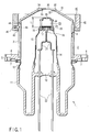
- FIG. 1 is a cross-sectional view of the x-ray tube 1.
- the x-ray tube 1 comprises a vacuum envelope 2 as the vacuum vessel which maintains vacuum tightness.
- the vacuum envelope 2 comprises a cylindrical cylinder portion 3, and the cylinder portion 3 has formed thereon an exhaust pipe mounting portion 4 for mounting the exhaust pipe (not shown) for vacuum exhaust. It is to be noted that the exhaust pipe mounting portion 4 is sealed off after the vacuum envelope 2 is evacuated.
- tube mounting fitting 5 which has a circular flange shape.
- This tube mounting fitting 5 has a plurality of screw insertion holes 6. Screws for fixing the tube mounting fitting 5 are inserted into the screw insertion holes 6.
- a double cylinder glass container 11 having a closed base end side is attached to the back surface side of the tube mounting fitting 5 which is the base end side of the cylinder portion 3.
- a circular-shape connecting body 12 which is made of metal is integrally attached to the front end of the opened outer cylinder of the glass container 11 by being welding or the like to the glass container.
- the connecting body 12 is welded to the tube fitting 5 and sealed so as to be air tight.
- a closing portion 13 for closing the inner cylinder is formed at the inner periphery side of the inner cylinder of the glass container 11. Furthermore, the circular-shape connecting body 14 which is made of metal is integrally attached to the front end of the inner cylinder of the glass container 11 by welding or the like to the glass container 11. A support body 15 is connected to the front end of the connecting body 14.
- a circular plate shaped holding body 16 is attached to the front end of the support body 15.
- a cathode holding body 17 is attached to the inside of the holding body 16.
- a cathode 18 is mounted to the cathode holding body 17.
- the cathode 18 has a built-in filament which is not shown, and this filament is heated to emit a thermal electron beam.
- the cathode 18 has a filament support portion 21 at the base end side thereof.
- a filament terminal 22 which passes through the closing portion 13 of the glass container 11 in an airtight state is connected to the filament support portion 21. External power is supplied to the cathode 18 via the filament support portion 21 from the filament terminal 22.
- An electrostatic focusing electrode body 23 which is the integrally formed electron lens is attached to the holding body 16.
- the focusing electrode body 23 and the cathode 18 form a microscopic focus electron gun.
- the focusing electrode body 23 has a rod-shaped electrode holding insulation body 24 attached to the holding body 16 and also has a first focusing electrode 25, a second focusing electrode 26, and a third focusing electrode 27, formed in that order from the cathode side along the electrode holding insulation body 24.
- the first focusing electrode 25 applies hundreds of minus voltage.
- the second focusing electrode 26 applies thousands of plus voltage.
- the third focusing electrode 27 is disposed via a somewhat large interval with respect to the second focusing electrode 26, and applies thousands of plus voltage.
- An electron beam insertion hole which is not shown is formed in the opening state in the center of the first focusing electrode 25 and the second focusing electrode 26.
- An electron beam insertion hole 28 which communicates linearly on the line extending from the electron beam insertion hole of the first focusing electrode 25 and the second focusing electrode 26 is formed in the center of the third focusing electrode 27.
- a lid 31 in which diameter become small toward the front end is attached to the front end side of the cylinder portion 3.
- An attaching portion 32 which has an opening 33 is formed at the front end of the lid 31.
- a target holding body 34 which has an opening 35 is held at the attaching portion 32.
- the transmission type target 36 which will become window is attached to the target holding body 34 as a part of the vacuum envelope 2 so as to be air tight.
- the target 36 is disposed so as to oppose the cathode 18 via the electron beam insertion hole of the first focusing electrode 25, the electron beam insertion hole of the second focusing electrode 26 and the electron beam insertion hole 28 of the third focusing electrode.
- the target 36 must be formed of a plate material with little x-ray transmissivity loss such as a thin beryllium plate or an Al substrate with a thickness in the hundreds of ⁇ m so that it may function as a vacuum airtight partition.
- a thin film of tungsten and the like with a thickness of 5 ⁇ m to 10 ⁇ m which can be the x-ray source is formed on the vacuum side of the plate material. It is to be noted that the thickness of the thin tungsten film is designed based on the depth required for passing the electron beam into the film and the attenuation rate of the generated x-ray.
- a magnet portion 40 is mounted to the outer periphery of the vacuum envelope 2.
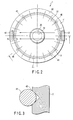
- the magnet portion 40 has a circular magnet holding body 41 disposed via the space between itself and the vacuum envelope 2.
- the magnet holding body 41 is mounted so as to be manually rotatable, for example, with respect to the vacuum envelope 2.
- Permanent magnets 42, 42 are mounted at a position which opposes the diameter direction of the magnet holding body 41.
- the permanent magnets 42, 42 are disposed to have directionality when different poles oppose each other, in order to form a magnet flux with strength of approximately 10 gauss to 50 gauss in the path of the electron beam.
- cone-shaped engagement holes 43 are formed, for example, at 20 locations at every 18° intervals on the outer periphery of the vacuum envelope 2.
- hole grooves 44 may be formed at 4 locations at every 90° intervals at the inner periphery of the magnet holding body 41, and ball presser springs 45 are inserted into the hole grooves 44, and balls 46 for positioning sizes that can be inserted in the hole grooves 44 are attached to the front ends of the ball presser springs 45.
- the ball 46 of the magnet holding body 41 is urged by the ball presser springs 45 in the central direction of the vacuum envelope 2, and the magnet holding body 41 is positioned at a prescribed rotation position by being engaged in the engagement hole 43 of the vacuum envelope 2.
- the line extending in the diameter direction which joins the permanent magnets 42 which oppose each other, cross the axis which passes through the center of the target 36, and the axial direction position is disposed at a position which includes the range L in the FIG. 1 which extends from the front end of the cathode 18 to the third focusing electrode 27 which is at a position closest to the target 36 side.
- the filament built into the cathode 18 is electrically heated and the cathode 18 emits a thermal electron beam.
- the electron beam is irradiated onto the target 36 via the focusing electrode body 23. More specifically, the electron beam which is emitted from the cathode 18 is focused with electron lens by hundreds of minus voltage from the first focusing electrode 25, and then focused further with thousands of plus voltage from the second focusing electrode 26 and the third focusing electrode 27. Voltage of approximately 100 kV is applied to the target 36 and an electron beam of 5 ⁇ m, for example, from the range of 2 ⁇ m to 5 ⁇ m is formed and focused on the vacuum side surface of target 36.
- the electron beam at this time is focused at a position which is slightly offset from the center of the target 36 because of the magnetic field formed by the permanent magnets 42 in the magnet portion 40.
- x-rays Due to the impact of the electron beam which is focused at the vacuum side surface of the target 36, x-rays are generated from the thin tungsten film of the target 36, and the x-rays pass through the thin beryllium plate and are sent outside and used as a x-ray source of precise testing device.
- the film surface of the x-ray source such as the thin tungsten film or the like increases in temperature and deteriorates, and the amount of x-rays generated decreases with the passage of time.
- the thin tungsten film reaches the end of its service life after about several hundreds to one thousand hours.
- the magnet holding body 41 of the magnet portion 40 is rotated manually or mechanically by 18° with the center of the vacuum envelope 2 as the rotation axis.
- the balls 46 resist the urging force of the ball presser springs 45 and are momentarily accommodated in the hole grooves 44, and then the balls 46 are urged again in the central direction of the vacuum envelope 2 by the ball presser springs 45 at the position of the adjoining engaging holes 43 and then engaged in the engaging holes 43 of the vacuum envelope 2.
- the rotated magnet holding body 41 is positioned at a prescribed position after being rotated by 18° .
- the angle in the diameter direction of the magnetic field formed by the permanent magnets 42 changes, and thus the electron beam is focused not at the position at which target 36 was previously irradiated, and for example, but at a position which has shifted by 50 ⁇ m to 100 ⁇ m.
- the electron beam impacts a new position on the thin tungsten film of the target 36, and generates the same amount of x-rays as that of the initial performance.
- the magnet holding body 41 can be positioned at 20 different rotation positions, and thus the irradiation position on the target 36 of the electron beam can be changed 20 times.
- the x-ray irradiation position moves sequentially from the initial position, but because the distance of movement is not more than 0.3 mm it is unnecessary to adjust the image receiving side of the test device after the x-ray is irradiated.
- the magnet holding body 41 is sequentially rotated after every set time period, and thus a service life of exceeding 10,000 hours is realized in a seal-off transmission type microfocus x-ray generating tube 1 in which the size of the focal point is several ⁇ m.
- the distance of movement of the irradiation position with respect to the rotation angle of the magnet holding body 41 can be made larger, and the movement amount of the irradiation position of the electron beam can be arbitrarily set in accordance with objective of the irradiation or the size of the device. It is to be noted that in the case where a system is employed in which permanent magnets 42 are used to shift the focal point of the electron beam as in this embodiment, it is necessary to focus on the target 36 without degrading the performance of the first focusing electrode 25, the second focusing electrode 26, and the third focusing electrode 27 which form the electron lens.
- the optimal position for disposing the permanent magnets 42 is set based on the strength of the permanent magnets 42, the distance of movement of the irradiation position, the diameter of the focal point, and the service life for use of the target 36. If the position of the permanent magnets 42 in the axial direction of the electron beam is between the first focusing electrode 25 and the target 36, the focus position which is to become the irradiation position may be moved, but if it is between the third focusing electrode 27 and the target 36, there is the possibility that there will be instability as the size of the focal point becomes uneven with the rotation of the magnet holding body 41, or there will be blurring at the periphery and performance will deteriorate.
- the position in the axial direction of the electron beam of the permanent magnets 42 is between the cathode 18 and the third focusing electrode 27.
- a annular outer fitting 51 which has an L-shaped cross-section is fit into the vacuum envelope 2 of the conventional x-ray tube which does not have engagement holes 43 at the outer periphery of the vacuum envelope 2, and the above-described magnet portion 40 is attached to the outer side of the outer fitting 51.
- the outer fitting 51 has engagement holes 52 which function in the same manner as the engagement holes 43 of the embodiment described in FIGS. 1 to 3 formed in advance therein. That is to say, by engaging the ball 46 of the magnet holding body 41 in the engaging holes 52, the magnet holding body 41 can be positioned at a prescribed rotation position.
- the outer fitting 51 is attached to the vacuum envelope 2 without reconstructing the x-ray tube itself and by attaching the magnet holding body 41 to the outer side of the outer fitting 51, the present invention can also be applied to the x-ray tube which does not have the conventional magnet portion 40. That is to say, in this embodiment also, the irradiation position of the electron beam on the target 36 can be moved, and the service life of the x-ray apparatus can be prolonged.
- FIG. 5 is basically the same as the embodiment described using FIGS. 1 to 3, but the magnet portion 60 replaces the permanent magnets 42, and 12 electromagnets 61 are fixed so as to have equal intervals on the periphery of the vacuum envelope 2. Each of the electromagnets 61 can change the polar direction by changing the current direction.
- a pair of electromagnets 61 which oppose each other in the diameter direction is selected, and this pair of electromagnets 61 is energized such that different poles oppose each other, and a magnetic field is thereby generated.
- the set of electromagnets 61 energized is changed, and the irradiation position on the target 36 of the electron beam is moved in the circumferential direction of the target 36. This operation is repeated and the electron beam sequentially irradiates the 12 different positions in the circumferential direction of the target 36.
- the irradiation position of the electron beam may be changed to different positions in the diameter direction of the target 36.
- electromagnets can be selectively energized without any portions that move mechanically, and the electron beam can irradiate arbitrary positions on the target 36 only by electrical control for changing the current value, and thus the irradiation position of the electron beam can be moved. That is to say, in the present embodiment also, the service life of the x-ray apparatus can be lengthened.
- magnetic flux of the electromagnet 61 must have strength in a range such that the focus of the first focusing electrode 25 through to the third focusing electrode 27 are not affected thereby, and there is no negative effect on focusing.
- the embodiment shown in FIG. 6 basically uses electromagnets in the same manner as the embodiment described refer to FIG. 5, but the magnet portion 65 is disposed such that 2 pairs of a total of four electromagnets 66 are fixed at equal intervals of 90° along the periphery of the vacuum envelope 2, and the energization of the electromagnets 66 are controlled by the control means 67.
- the electric energizing amount and the current direction of the 4 electromagnets 66 are controlled by the control means 67, and the direction and strength of the 2 magnetic fluxes which intersect on the tube axis are changed and arbitrary magnetic flux is synthesized. As a result, the electron beam can be irradiated on a arbitrary position of the target 36.
- the electron beam can be irradiated on a arbitrary position of the target 36 using a smaller electromagnet 66, and the irradiation position of the electron beam can be freely moved. That is to say, in this embodiment also, the service life of the x-ray apparatus can be lengthened.
- the irradiation position of the electron beam can be moved to another position of the target due to the effect of a magnet portion.
- the initial performance can be obtained and service life can be lengthened.
Landscapes
- X-Ray Techniques (AREA)
Applications Claiming Priority (3)
| Application Number | Priority Date | Filing Date | Title |
|---|---|---|---|
| JP2003004674A JP2004265602A (ja) | 2003-01-10 | 2003-01-10 | X線装置 |
| JP2003004674 | 2003-01-10 | ||
| PCT/JP2004/000120 WO2004064106A1 (fr) | 2003-01-10 | 2004-01-09 | Equipement a rayons x |
Publications (1)
| Publication Number | Publication Date |
|---|---|
| EP1596417A1 true EP1596417A1 (fr) | 2005-11-16 |
Family
ID=32708969
Family Applications (1)
| Application Number | Title | Priority Date | Filing Date |
|---|---|---|---|
| EP04701122A Withdrawn EP1596417A1 (fr) | 2003-01-10 | 2004-01-09 | Equipement a rayons x |
Country Status (5)
| Country | Link |
|---|---|
| US (1) | US7206381B2 (fr) |
| EP (1) | EP1596417A1 (fr) |
| JP (1) | JP2004265602A (fr) |
| CN (1) | CN1698175A (fr) |
| WO (1) | WO2004064106A1 (fr) |
Families Citing this family (44)
| Publication number | Priority date | Publication date | Assignee | Title |
|---|---|---|---|---|
| US7428298B2 (en) * | 2005-03-31 | 2008-09-23 | Moxtek, Inc. | Magnetic head for X-ray source |
| JP2007066694A (ja) | 2005-08-31 | 2007-03-15 | Hamamatsu Photonics Kk | X線管 |
| US20070274435A1 (en) * | 2006-02-27 | 2007-11-29 | Ruola Ning | Phase contrast cone-beam CT imaging |
| US7639785B2 (en) * | 2007-02-21 | 2009-12-29 | L-3 Communications Corporation | Compact scanned electron-beam x-ray source |
| US20110121179A1 (en) * | 2007-06-01 | 2011-05-26 | Liddiard Steven D | X-ray window with beryllium support structure |
| US7737424B2 (en) * | 2007-06-01 | 2010-06-15 | Moxtek, Inc. | X-ray window with grid structure |
| US8237431B2 (en) * | 2007-07-05 | 2012-08-07 | Terry Fruehling | Wheel speed sensor |
| WO2009009610A2 (fr) * | 2007-07-09 | 2009-01-15 | Brigham Young University | Procédés et dispositifs pour une manipulation de molécules chargées |
| US7529345B2 (en) * | 2007-07-18 | 2009-05-05 | Moxtek, Inc. | Cathode header optic for x-ray tube |
| WO2009085351A2 (fr) * | 2007-09-28 | 2009-07-09 | Brigham Young University | Fenêtre à rayons x avec cadre en nanotube en carbone |
| EP2190778A4 (fr) * | 2007-09-28 | 2014-08-13 | Univ Brigham Young | Ensemble de nanotubes de carbone |
| US8498381B2 (en) | 2010-10-07 | 2013-07-30 | Moxtek, Inc. | Polymer layer on X-ray window |
| US9305735B2 (en) | 2007-09-28 | 2016-04-05 | Brigham Young University | Reinforced polymer x-ray window |
| US8247971B1 (en) | 2009-03-19 | 2012-08-21 | Moxtek, Inc. | Resistively heated small planar filament |
| US20100239828A1 (en) * | 2009-03-19 | 2010-09-23 | Cornaby Sterling W | Resistively heated small planar filament |
| US7983394B2 (en) * | 2009-12-17 | 2011-07-19 | Moxtek, Inc. | Multiple wavelength X-ray source |
| US8526574B2 (en) | 2010-09-24 | 2013-09-03 | Moxtek, Inc. | Capacitor AC power coupling across high DC voltage differential |
| US8995621B2 (en) | 2010-09-24 | 2015-03-31 | Moxtek, Inc. | Compact X-ray source |
| US8804910B1 (en) | 2011-01-24 | 2014-08-12 | Moxtek, Inc. | Reduced power consumption X-ray source |
| US8750458B1 (en) | 2011-02-17 | 2014-06-10 | Moxtek, Inc. | Cold electron number amplifier |
| US8929515B2 (en) | 2011-02-23 | 2015-01-06 | Moxtek, Inc. | Multiple-size support for X-ray window |
| US8792619B2 (en) | 2011-03-30 | 2014-07-29 | Moxtek, Inc. | X-ray tube with semiconductor coating |
| US9174412B2 (en) | 2011-05-16 | 2015-11-03 | Brigham Young University | High strength carbon fiber composite wafers for microfabrication |
| US8989354B2 (en) | 2011-05-16 | 2015-03-24 | Brigham Young University | Carbon composite support structure |
| US9076628B2 (en) | 2011-05-16 | 2015-07-07 | Brigham Young University | Variable radius taper x-ray window support structure |
| US8817950B2 (en) | 2011-12-22 | 2014-08-26 | Moxtek, Inc. | X-ray tube to power supply connector |
| US8761344B2 (en) | 2011-12-29 | 2014-06-24 | Moxtek, Inc. | Small x-ray tube with electron beam control optics |
| US9072154B2 (en) | 2012-12-21 | 2015-06-30 | Moxtek, Inc. | Grid voltage generation for x-ray tube |
| US9364191B2 (en) | 2013-02-11 | 2016-06-14 | University Of Rochester | Method and apparatus of spectral differential phase-contrast cone-beam CT and hybrid cone-beam CT |
| US9184020B2 (en) | 2013-03-04 | 2015-11-10 | Moxtek, Inc. | Tiltable or deflectable anode x-ray tube |
| US9177755B2 (en) | 2013-03-04 | 2015-11-03 | Moxtek, Inc. | Multi-target X-ray tube with stationary electron beam position |
| US9173623B2 (en) | 2013-04-19 | 2015-11-03 | Samuel Soonho Lee | X-ray tube and receiver inside mouth |
| JP6100611B2 (ja) * | 2013-05-27 | 2017-03-22 | 浜松ホトニクス株式会社 | X線発生装置 |
| JP6611490B2 (ja) * | 2015-07-02 | 2019-11-27 | キヤノン株式会社 | X線発生装置及びこれを用いたx線撮影システム |
| JP6667366B2 (ja) * | 2016-05-23 | 2020-03-18 | キヤノン株式会社 | X線発生管、x線発生装置、およびx線撮影システム |
| JP6867224B2 (ja) * | 2017-04-28 | 2021-04-28 | 浜松ホトニクス株式会社 | X線管及びx線発生装置 |
| JP6849518B2 (ja) * | 2017-04-28 | 2021-03-24 | 浜松ホトニクス株式会社 | X線管及びx線発生装置 |
| GB2565138A (en) * | 2017-08-04 | 2019-02-06 | Adaptix Ltd | X-ray generator |
| CN109738474A (zh) * | 2019-01-28 | 2019-05-10 | 深圳市纳诺艾医疗科技有限公司 | 一种能谱可调的本地二次荧光辐射装置 |
| JP7505993B2 (ja) * | 2021-01-22 | 2024-06-25 | 浜松ホトニクス株式会社 | X線モジュール |
| US11721515B2 (en) * | 2021-01-22 | 2023-08-08 | Hamamatsu Photonics K.K. | X-ray module |
| JP7505992B2 (ja) * | 2021-01-22 | 2024-06-25 | 浜松ホトニクス株式会社 | X線モジュール |
| JP7636977B2 (ja) * | 2021-06-24 | 2025-02-27 | 浜松ホトニクス株式会社 | X線発生装置 |
| KR102914390B1 (ko) * | 2022-09-15 | 2026-01-20 | 캐논 아네르바 가부시키가이샤 | X선 발생 장치, x선 촬상 장치, 및, x선 발생 장치의 조정 방법 |
Family Cites Families (10)
| Publication number | Priority date | Publication date | Assignee | Title |
|---|---|---|---|---|
| US4048496A (en) * | 1972-05-08 | 1977-09-13 | Albert Richard D | Selectable wavelength X-ray source, spectrometer and assay method |
| JPS5316287Y2 (fr) * | 1973-03-27 | 1978-04-28 | ||
| FR2386109A1 (fr) * | 1977-04-01 | 1978-10-27 | Cgr Mev | Tete d'irradiation a rayons g pour une irradiation panoramique et generateur de rayons g comportant une telle tete d'irradiation |
| JPS60400A (ja) * | 1983-06-16 | 1985-01-05 | 株式会社東芝 | 全周照射型x線装置 |
| JPH0322331A (ja) | 1989-06-20 | 1991-01-30 | Sanyo Electric Co Ltd | X線管球 |
| JPH06188092A (ja) * | 1992-12-17 | 1994-07-08 | Hitachi Ltd | X線発生用タ−ゲットとx線源とx線撮像装置 |
| US6236713B1 (en) * | 1998-10-27 | 2001-05-22 | Litton Systems, Inc. | X-ray tube providing variable imaging spot size |
| DE19903872C2 (de) * | 1999-02-01 | 2000-11-23 | Siemens Ag | Röntgenröhre mit Springfokus zur vergrößerten Auflösung |
| GB9906886D0 (en) * | 1999-03-26 | 1999-05-19 | Bede Scient Instr Ltd | Method and apparatus for prolonging the life of an X-ray target |
| DE10120808C2 (de) * | 2001-04-27 | 2003-03-13 | Siemens Ag | Röntgenröhre, insbesondere Drehkolbenröntgenröhre |
-
2003
- 2003-01-10 JP JP2003004674A patent/JP2004265602A/ja active Pending
-
2004
- 2004-01-09 CN CNA2004800000684A patent/CN1698175A/zh active Pending
- 2004-01-09 EP EP04701122A patent/EP1596417A1/fr not_active Withdrawn
- 2004-01-09 US US10/507,204 patent/US7206381B2/en not_active Expired - Lifetime
- 2004-01-09 WO PCT/JP2004/000120 patent/WO2004064106A1/fr not_active Ceased
Non-Patent Citations (1)
| Title |
|---|
| See references of WO2004064106A1 * |
Also Published As
| Publication number | Publication date |
|---|---|
| US7206381B2 (en) | 2007-04-17 |
| US20050141669A1 (en) | 2005-06-30 |
| JP2004265602A (ja) | 2004-09-24 |
| WO2004064106A1 (fr) | 2004-07-29 |
| CN1698175A (zh) | 2005-11-16 |
Similar Documents
| Publication | Publication Date | Title |
|---|---|---|
| US7206381B2 (en) | X-ray equipment | |
| EP1096543B1 (fr) | Tube a rayons x | |
| US7428298B2 (en) | Magnetic head for X-ray source | |
| US9653248B2 (en) | X-ray tube | |
| CN107452584B (zh) | X射线发生管、x射线发生装置和放射线照相系统 | |
| WO2014123835A1 (fr) | Source de rayons x à vie utile de cible améliorée | |
| JP2015191795A (ja) | X線発生装置 | |
| US20120281815A1 (en) | X-ray tube and method to operate an x-ray tube | |
| EP4080541A2 (fr) | Procédé et système de refroidissement par liquide d'une cible de transmission de rayons x isolée | |
| JP4886760B2 (ja) | X線装置 | |
| US20240321542A1 (en) | X-ray generation device | |
| JP4309176B2 (ja) | X線装置 | |
| US12106927B2 (en) | X-ray generation apparatus, x-ray imaging apparatus, and adjustment method of x-ray generation apparatus | |
| US12597581B2 (en) | X-ray generation device | |
| JP2018060621A (ja) | X線管 | |
| US3508049A (en) | Corpuscular-ray microscope with an objective lens which also forms a condenser-lens field | |
| EP4090137A2 (fr) | Source de rayons x avec bobines de source refroidies par liquide | |
| CN117501398A (zh) | X射线产生装置 | |
| TWI916550B (zh) | X光產生裝置 | |
| WO2023188337A1 (fr) | Dispositif de génération de rayons x, dispositif d'imagerie à rayons x et procédé de réglage de dispositif de génération de rayons x | |
| JP2008071549A (ja) | X線管装置 |
Legal Events
| Date | Code | Title | Description |
|---|---|---|---|
| PUAI | Public reference made under article 153(3) epc to a published international application that has entered the european phase |
Free format text: ORIGINAL CODE: 0009012 |
|
| 17P | Request for examination filed |
Effective date: 20040915 |
|
| AK | Designated contracting states |
Kind code of ref document: A1 Designated state(s): AT BE BG CH CY CZ DE DK EE ES FI FR GB GR HU IE IT LI LU MC NL PT RO SE SI SK TR |
|
| AX | Request for extension of the european patent |
Extension state: AL LT LV MK |
|
| RIN1 | Information on inventor provided before grant (corrected) |
Inventor name: SHIMIZU, KATSUNORI C/O TOSHIBA CORPORATION Inventor name: SHIMONO, TAKASHI C/O TOSHIBA CORPORATION |
|
| DAX | Request for extension of the european patent (deleted) | ||
| RBV | Designated contracting states (corrected) |
Designated state(s): DE GB |
|
| STAA | Information on the status of an ep patent application or granted ep patent |
Free format text: STATUS: THE APPLICATION HAS BEEN WITHDRAWN |
|
| 18W | Application withdrawn |
Effective date: 20090217 |