EP1437883A1 - Procédé pour la génération d'une représentation tramée d'une image - Google Patents
Procédé pour la génération d'une représentation tramée d'une image Download PDFInfo
- Publication number
- EP1437883A1 EP1437883A1 EP20030104500 EP03104500A EP1437883A1 EP 1437883 A1 EP1437883 A1 EP 1437883A1 EP 20030104500 EP20030104500 EP 20030104500 EP 03104500 A EP03104500 A EP 03104500A EP 1437883 A1 EP1437883 A1 EP 1437883A1
- Authority
- EP
- European Patent Office
- Prior art keywords
- dots
- dot
- microdots
- size
- image
- Prior art date
- Legal status (The legal status is an assumption and is not a legal conclusion. Google has not performed a legal analysis and makes no representation as to the accuracy of the status listed.)
- Withdrawn
Links
Images


Classifications
-
- H—ELECTRICITY
- H04—ELECTRIC COMMUNICATION TECHNIQUE
- H04N—PICTORIAL COMMUNICATION, e.g. TELEVISION
- H04N1/00—Scanning, transmission or reproduction of documents or the like, e.g. facsimile transmission; Details thereof
- H04N1/40—Picture signal circuits
- H04N1/405—Halftoning, i.e. converting the picture signal of a continuous-tone original into a corresponding signal showing only two levels
- H04N1/4055—Halftoning, i.e. converting the picture signal of a continuous-tone original into a corresponding signal showing only two levels producing a clustered dots or a size modulated halftone pattern
Definitions
- the present invention relates to the halftoning of continuous tone images for use in reproduction of such images.
- reproduction devices are not capable of reproducing a continuous range of tones.
- offset printing or inkjet printing methods can either deposit ink or not.
- Several techniques have been developed to simulate continuous tones on such devices. These simulated continuous tones are called halftones.
- the process that is used to obtain halftones is called screening. Screening breaks an image down into a series of dots. Varying the dot sizes, the number of dots, or both, approximates shades of color. The eye is not able to see the individual halftone dots, and only sees the corresponding "spatially integrated" density value.
- a black-and-white printed image for example, a group of large dots placed closely together appears black. A group of smaller dots with larger spaces between them produces a weaker, gray shade. A group of even smaller dots spaced widely apart appears almost white.
- Imagesetters create an electronic version of the traditional halftone screen. Screening software in the imagesetter applies an electronic dot pattern to the electronic image. In electronic screening, the halftone dots are made up of several microdots; a microdot is the smallest unit that can be addressed by the imagesetter.
- AM screening Amplitude Modulated screening
- FM screening Frequency Modulated screening
- AM screening the halftone dots, that together will give the impression of a particular tone, are arranged on a fixed geometric grid. By varying the size of the halftone dots, the different tones of images can be simulated.
- AM screening is also called dot-size modulation screening or dot-clustered screening.
- FM screening the distance between the halftone dots is modulated rather then their size.
- FM screening is also called stochastic screening or dot-dispersed screening.
- Agfa's CristalRaster is an example of FM screening
- Agfa Balanced Screening (ABS) is an AM screening technology. More information on AM and FM screening can be found in EP-A-0 639 023 .
- the present invention is a method for generating a screened representation of an image as claimed in independent claim 1. Preferred embodiments of the invention are set out in the dependent claims. Preferably, a method in accordance with the invention is implemented by a computer program as claimed in claim 9. The invention also includes a printing plate as claimed in claim 6.
- a screening method in accordance with the invention is partially FM and partially AM.
- FM screening is applied to the highlights and the shadows
- AM screening is applied to the midtones.
- FM dots are generated.
- these FM dots are enlarged by adding one or more microdots to them, i.e. the dots "grow” - which is AM screening.
- remaining "holes" between the dots are removed - which is FM screening again.
- An advantage of a method in accordance with the invention is that clustering of dots in the midtones is more controllable, resulting in a higher perceived quality of the printed image in the midtones. Another advantage is that, depending on the design of the writing heads of some imagers, some severe banding is avoided.
- FIG. 1A shows a number of first dots 11, arranged in a frequency modulated pattern.
- This frequency modulated pattern may be obtained by means of a randomized Bayer matrix, as disclosed in EP-A-0 642 259 and as used in Agfa's CristalRaster.
- the first dots 11 all have a first dot size. With increasing density, more first dots 11, having this first dot size, may be added to those shown in Fig. 1A. With still further increasing density, as shown in Fig.
- a number of second dots 12, selected out of the first dots 11, are enlarged by adding one or more microdots 13 to these second dots 12.
- the number of second dots 12 is at most equal to, i.e. is smaller than or equal to, the number of first dots 11 (remark: in order to keep the drawings readable, only some of the first dots 11, second dots 12 and microdots 13 are indicated by reference signs in Figs. 1A - 1F).
- Figs. 1A and 1B illustrate a first embodiment of the invention, wherein first FM screening is applied (see Fig. 1A) and then AM (Fig. 1B).
- the second dots 12 grow further by the addition of microdots.
- Fig. 1A first FM screening is applied
- AM Fig. 1B
- FIG. 1D which illustrates a second embodiment of the invention
- all the second dots 12 have grown from the first dot size (of the first dots 11 in Fig. 1A) to a second dot size.
- the location of the dots is determined as follows.
- a randomized Bayer matrix is generated; this matrix is subdivided into a plurality of parcels; the parcels themselves may be subdivided again, in a number of steps as disclosed in EP-A-0 642 259 cited already above, until the finally obtained parcels have a parcel size equal to the second dot size, i.e. of 3x3 microdots.
- the first dots 11 having a first dot size of 2x2 microdots are generated in a 3x3 CristalRaster screen. With increasing density, these dots then gradually grow, and all have a second dot size equal to the parcel size of 3x3 microdots in Fig. 1D.
- Fig. 1A the first dots 11 having a first dot size of 2x2 microdots are generated in a 3x3 CristalRaster screen. With increasing density, these dots then gradually grow, and all have a second dot size equal to the parcel size of 3x3 microdots in Fig. 1D.
- the microdots that are not turned on, i.e. that are not black, can be regarded as white "holes" 14.
- These holes 14 have a size equal to the second dot size, i.e. 3x3 microdots, in Fig. 1D.
- the size of the holes 14 is gradually decreased, from a size equal to the second dot size of 3x3 microdots in Fig. 1D to a size equal to the first dot size of 2x2 microdots in Fig. 1F, by gradually turning on microdots in the holes, as shown in Fig. 1E.
- the remaining holes 15 have a size of 2x2 microdots; moreover, some of the holes were already removed completely in Fig. 1F to increase density still further.
- the invention is not limited to the embodiment discussed above.
- the dots grow from a size of 2x2 microdots to a size of 3x3 microdots, but of course other dot sizes may be used, such as 1x1, 2x3, 2x1, etc.
- any mask-based FM screening method that makes use of a threshold mask array may be applied.
- the so-called blue noise mask method (disclosed in US-A-5 111 310 ) is an example of a mask-based FM screening method.
- the threshold mask array is then subdivided into a plurality of parcels, as discussed above.
- Fig. 2 illustrates in detail a way of gradually increasing the dot size, and decreasing the hole size.
- a square of only 9x9 microdots 13 is shown; in reality, a threshold mask array will usually comprise many more microdots, e.g. 512x512 microdots.
- each of the microdots 13 of the square of 9x9 microdots 13 has a number inside. These numbers inside the microdots are not reference signs; they indicate the sequence wherein the microdots are added, i.e. turned on, as explained below.
- the square of 9x9 microdots is divided by lines 18 into four adjacent dots having a dot size of 3x3 microdots.
- the microdots are turned on according to the following sequence. First, the four microdots with number 0 are turned on, and then the four microdots with number 1, so that two dots 11, called first dots 11 in Fig. 1A, are generated. These first dots 11 have a dot size of 2x2 microdots. Then, these first dots 11 grow: the microdot with number 2 is turned on, then the microdot with number 3, then number 4, etc. After adding the microdot with number 11, both first dots 11 now have a size of 3x3 dots, and two 3x3 holes remain, in the upper right and the lower left quadrants of the 9x9 square.
- the size of these holes is gradually decreased, by turning on the microdot with number 12, then 13, and so on, until number 21. Now two holes 15 with size 2x2 microdots remain. By adding the four microdots with number 22, and then the four microdots with number 23, all the microdots are turned on, so that a density of 100 % is reached.
- a given number of first dots are generated, so that a predetermined density is reached, before the dots start to grow.
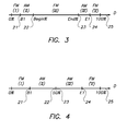
- This can be realized by the following algorithm, that is illustrated by Fig. 3 showing values along a density axis D:
- the dots are square.
- the algorithm can however easily be generalized to rectangular dots, by replacing the parameter BeginSize by two different parameters, BeginSize1 and BeginSize2, and by replacing EndSize by EndSizel and EndSize2.
- End% 100 - Begin%
- the algorithm is symmetrical with respect to dots and holes.
- Fig. 4 illustrates how density varies for the embodiment discussed already above in connection with Figs. 1A - 1F.
- Fig. 5 shows "grown" dots 12 of an embodiment in accordance with the invention.
- the same density can also be obtained, by a prior art method as shown in Fig. 6, by turning on four dots of 2*2 microdots (so that also 16 of the 36 microdots are turned on).
- Another advantage of the invention is that, depending on the design of the writing heads of some imagers, some severe banding is avoided. E.g. when interlaced imaging is used, in known FM screens that make use of a single dot size very often a disturbing pattern is observed. Using a screen in accordance with the invention may then solve this problem.
- Yet another advantage of the invention is that a higher screen stability is combined with good reproduction of fine details in the highlights and shadows.
- larger dots are used (e.g. 3x3 instead of 2x2) which is more stable in the imagesetter (or platesetter) and in the pressroom.
- the invention can advantageously be used for computer-to-plate packaging applications.
- the invention also includes a printing plate and a printing plate precursor made by a method in accordance with the invention.
- a printing plate precursor is an imaging material that can be used as a printing plate after one or more treatment steps, that generally include image-wise exposure and processing. Such a printing plate precursor is exposed according to a screened representation in accordance with the invention.
- a printing plate precursor or a printing plate in accordance with the invention has ink-accepting areas and non-ink-accepting areas that correspond to a screened representation in accordance with the invention.
Landscapes
- Engineering & Computer Science (AREA)
- Multimedia (AREA)
- Signal Processing (AREA)
- Manufacture Or Reproduction Of Printing Formes (AREA)
Priority Applications (1)
| Application Number | Priority Date | Filing Date | Title |
|---|---|---|---|
| EP20030104500 EP1437883A1 (fr) | 2002-12-05 | 2003-12-02 | Procédé pour la génération d'une représentation tramée d'une image |
Applications Claiming Priority (3)
| Application Number | Priority Date | Filing Date | Title |
|---|---|---|---|
| EP02102684 | 2002-12-05 | ||
| EP02102684 | 2002-12-05 | ||
| EP20030104500 EP1437883A1 (fr) | 2002-12-05 | 2003-12-02 | Procédé pour la génération d'une représentation tramée d'une image |
Publications (1)
| Publication Number | Publication Date |
|---|---|
| EP1437883A1 true EP1437883A1 (fr) | 2004-07-14 |
Family
ID=32718493
Family Applications (1)
| Application Number | Title | Priority Date | Filing Date |
|---|---|---|---|
| EP20030104500 Withdrawn EP1437883A1 (fr) | 2002-12-05 | 2003-12-02 | Procédé pour la génération d'une représentation tramée d'une image |
Country Status (2)
| Country | Link |
|---|---|
| US (1) | US20040136035A1 (fr) |
| EP (1) | EP1437883A1 (fr) |
Families Citing this family (2)
| Publication number | Priority date | Publication date | Assignee | Title |
|---|---|---|---|---|
| US7075677B1 (en) * | 2000-06-30 | 2006-07-11 | Silverbrook Research Pty Ltd | Ink jet fault tolerance using oversize drops |
| JP6358417B2 (ja) * | 2013-08-20 | 2018-07-18 | セイコーエプソン株式会社 | 印刷装置および印刷方法 |
Citations (3)
| Publication number | Priority date | Publication date | Assignee | Title |
|---|---|---|---|---|
| US4517605A (en) * | 1981-02-27 | 1985-05-14 | Canon Kabushiki Kaisha | Image signal processing apparatus |
| US5892588A (en) * | 1997-10-02 | 1999-04-06 | Professional Software Technologies Inc. | Digital halftoning combining dot size modulation screen with dot frequency modulation screen within a single image |
| US6433891B1 (en) * | 1998-12-14 | 2002-08-13 | Oak Technology, Inc. | Stochastic screening method with dot pattern regularity control and dot growth |
Family Cites Families (8)
| Publication number | Priority date | Publication date | Assignee | Title |
|---|---|---|---|---|
| US5111310A (en) * | 1990-12-04 | 1992-05-05 | Research Technologies Corporation, Inc. | Method and apparatus for halftone rendering of a gray scale image using a blue noise mask |
| JPH07264402A (ja) * | 1994-03-18 | 1995-10-13 | Dainippon Screen Mfg Co Ltd | 印刷版画像の作成方法 |
| EP0910206B1 (fr) * | 1995-04-28 | 2001-10-10 | Agfa-Gevaert N.V. | Trame de demi-teintes et son procédé de fabrication |
| US5740279A (en) * | 1996-11-26 | 1998-04-14 | Xerox Corporation | Cluster dot halftoning system |
| US6118935A (en) * | 1997-04-01 | 2000-09-12 | Professional Software Technologies, Inc. | Digital halftoning combining multiple screens within a single image |
| US6445465B1 (en) * | 1997-10-02 | 2002-09-03 | Pcc Artwork Systems | Digital halftoning combining dot size modulation screen with dot frequency modulation screen within a single image |
| US6507666B1 (en) * | 1999-05-19 | 2003-01-14 | Jesus Hill De La Torre | Method and apparatus for compensating for dot gain in stochastic printing |
| US6441923B1 (en) * | 1999-06-28 | 2002-08-27 | Xerox Corporation | Dynamic creation of color test patterns based on variable print settings for improved color calibration |
-
2003
- 2003-12-02 EP EP20030104500 patent/EP1437883A1/fr not_active Withdrawn
- 2003-12-02 US US10/725,739 patent/US20040136035A1/en not_active Abandoned
Patent Citations (3)
| Publication number | Priority date | Publication date | Assignee | Title |
|---|---|---|---|---|
| US4517605A (en) * | 1981-02-27 | 1985-05-14 | Canon Kabushiki Kaisha | Image signal processing apparatus |
| US5892588A (en) * | 1997-10-02 | 1999-04-06 | Professional Software Technologies Inc. | Digital halftoning combining dot size modulation screen with dot frequency modulation screen within a single image |
| US6433891B1 (en) * | 1998-12-14 | 2002-08-13 | Oak Technology, Inc. | Stochastic screening method with dot pattern regularity control and dot growth |
Non-Patent Citations (3)
| Title |
|---|
| BARTELS R: "Reducing Patterns in the FM Part of Tile-Based Hybrid Screens", PICS 2002: IS&T'S PICS CONFERENCE, April 2002 (2002-04-01), Portland, Oregon, USA, pages 241 - 244, XP002231672, ISSN: 0-89208-238-0 * |
| COOK C C: "COLOR DIGITAL HALFTONING USING MULTI-CLUSTER HALFTONE DOTS", RASTER IMAGING AND DIGITAL TYPOGRAPHY PROCEEDINGS OF THE INTERNATIONAL CONFERENCE, CAMBRIDGE, GB, 1991, pages 120 - 126,126A,127, XP000866055 * |
| KANG H R: "Dispersed Micro-Cluster Halftoning", NIP11, IS&T'S NIP CONFERENCE, 1995, pages 427 - 430, XP002231673, ISSN: 0-89208-187-2 * |
Also Published As
| Publication number | Publication date |
|---|---|
| US20040136035A1 (en) | 2004-07-15 |
Similar Documents
| Publication | Publication Date | Title |
|---|---|---|
| EP0560872B1 (fr) | Procede et appareil pour rendre en demi-teinte une image d'echelle de gris a l'aide d'un masque de bruit de bleu | |
| US5726772A (en) | Method and apparatus for halftone rendering of a gray scale image using a blue noise mask | |
| JP3077873B2 (ja) | 印刷版画像の作成方法および装置 | |
| EP0642259B1 (fr) | Procede de fabrication d une trame de demi-teintes à modulation de fréquence | |
| JP4017217B2 (ja) | 多色画像作成装置 | |
| EP1318662A2 (fr) | Obtention de demi-teintes avec positionnement des points uniformément dispersés | |
| EP1422925A2 (fr) | Méthode et appareil utilisant un tramage en demi-teintes stochastique et anisotrope avec des éléments d'image anamorphes | |
| US6962400B2 (en) | Sub-dot phase modulation for computer to plate inkjet system | |
| EP0642258B1 (fr) | Procédé pour obtenir une image tramée par modulation en fréquence | |
| US7342685B2 (en) | Constraint correlation for computer to plate inkjet system | |
| CN102812696B (zh) | 用于从多位图像数据产生1位图像数据的设备和方法 | |
| EP0721278B1 (fr) | Procédé pour la production d'une matrice de seuil et méthode et appareil pour la génération d'images en demi-teintes | |
| EP1437883A1 (fr) | Procédé pour la génération d'une représentation tramée d'une image | |
| EP1401190B1 (fr) | Modulation de la phase des sous-points pour les systèmes d'ordinateur à plaque par jet d'encre | |
| CN1867033A (zh) | 多配置网板色调系统 | |
| US5764810A (en) | Screenless conversion of continuous tone images with alterable dot spacing patterns | |
| JPH10210292A (ja) | 混成ハーフトーンスクリーン生成法 | |
| US20050243377A1 (en) | Method for generating non-printing dots in a screened representation of an image | |
| JP2002211097A (ja) | 複数のスクリーン線数を用いる網点生成処理方法 | |
| JP2001186330A (ja) | 中間調付きデジタル画像への情報埋め込み | |
| JPH1070658A (ja) | 閾値マトリクスパターンの作成方法およびハーフトーン画像の記録方法 | |
| JPH08228289A (ja) | 連続トーン再現方法及び連続トーン再現デバイス | |
| US20070064271A1 (en) | Image processing apparatus and method thereof |
Legal Events
| Date | Code | Title | Description |
|---|---|---|---|
| PUAI | Public reference made under article 153(3) epc to a published international application that has entered the european phase |
Free format text: ORIGINAL CODE: 0009012 |
|
| AK | Designated contracting states |
Kind code of ref document: A1 Designated state(s): AT BE BG CH CY CZ DE DK EE ES FI FR GB GR HU IE IT LI LU MC NL PT RO SE SI SK TR |
|
| AX | Request for extension of the european patent |
Extension state: AL LT LV MK |
|
| 17P | Request for examination filed |
Effective date: 20050114 |
|
| AKX | Designation fees paid |
Designated state(s): DE FR GB |
|
| 17Q | First examination report despatched |
Effective date: 20050330 |
|
| 17Q | First examination report despatched |
Effective date: 20050330 |
|
| RAP1 | Party data changed (applicant data changed or rights of an application transferred) |
Owner name: AGFA GRAPHICS N.V. |
|
| GRAP | Despatch of communication of intention to grant a patent |
Free format text: ORIGINAL CODE: EPIDOSNIGR1 |
|
| STAA | Information on the status of an ep patent application or granted ep patent |
Free format text: STATUS: THE APPLICATION IS DEEMED TO BE WITHDRAWN |
|
| 18D | Application deemed to be withdrawn |
Effective date: 20090423 |