EP1439236B1 - Verfahren zum trocknen eines oxidiertes metall enthaltenden formkörpers, verfahren zum reduzieren von oxidiertem metall und drehherd-metallreduktionsofen - Google Patents
Verfahren zum trocknen eines oxidiertes metall enthaltenden formkörpers, verfahren zum reduzieren von oxidiertem metall und drehherd-metallreduktionsofen Download PDFInfo
- Publication number
- EP1439236B1 EP1439236B1 EP02708751A EP02708751A EP1439236B1 EP 1439236 B1 EP1439236 B1 EP 1439236B1 EP 02708751 A EP02708751 A EP 02708751A EP 02708751 A EP02708751 A EP 02708751A EP 1439236 B1 EP1439236 B1 EP 1439236B1
- Authority
- EP
- European Patent Office
- Prior art keywords
- compacts
- drying
- water
- furnace
- hearth
- Prior art date
- Legal status (The legal status is an assumption and is not a legal conclusion. Google has not performed a legal analysis and makes no representation as to the accuracy of the status listed.)
- Expired - Lifetime
Links
Images


Classifications
-
- F—MECHANICAL ENGINEERING; LIGHTING; HEATING; WEAPONS; BLASTING
- F27—FURNACES; KILNS; OVENS; RETORTS
- F27B—FURNACES, KILNS, OVENS OR RETORTS IN GENERAL; OPEN SINTERING OR LIKE APPARATUS
- F27B9/00—Furnaces through which the charge is moved mechanically, e.g. of tunnel type; Similar furnaces in which the charge moves by gravity
- F27B9/14—Furnaces through which the charge is moved mechanically, e.g. of tunnel type; Similar furnaces in which the charge moves by gravity characterised by the path of the charge during treatment; characterised by the means by which the charge is moved during treatment
- F27B9/16—Furnaces through which the charge is moved mechanically, e.g. of tunnel type; Similar furnaces in which the charge moves by gravity characterised by the path of the charge during treatment; characterised by the means by which the charge is moved during treatment the charge moving in a circular or arcuate path
-
- C—CHEMISTRY; METALLURGY
- C21—METALLURGY OF IRON
- C21B—MANUFACTURE OF IRON OR STEEL
- C21B13/00—Making spongy iron or liquid steel, by direct processes
- C21B13/10—Making spongy iron or liquid steel, by direct processes in hearth-type furnaces
-
- C—CHEMISTRY; METALLURGY
- C21—METALLURGY OF IRON
- C21B—MANUFACTURE OF IRON OR STEEL
- C21B13/00—Making spongy iron or liquid steel, by direct processes
- C21B13/0046—Making spongy iron or liquid steel, by direct processes making metallised agglomerates or iron oxide
-
- C—CHEMISTRY; METALLURGY
- C21—METALLURGY OF IRON
- C21B—MANUFACTURE OF IRON OR STEEL
- C21B13/00—Making spongy iron or liquid steel, by direct processes
- C21B13/10—Making spongy iron or liquid steel, by direct processes in hearth-type furnaces
- C21B13/105—Rotary hearth-type furnaces
-
- F—MECHANICAL ENGINEERING; LIGHTING; HEATING; WEAPONS; BLASTING
- F27—FURNACES; KILNS; OVENS; RETORTS
- F27B—FURNACES, KILNS, OVENS OR RETORTS IN GENERAL; OPEN SINTERING OR LIKE APPARATUS
- F27B9/00—Furnaces through which the charge is moved mechanically, e.g. of tunnel type; Similar furnaces in which the charge moves by gravity
- F27B9/30—Details, accessories or equipment specially adapted for furnaces of these types
- F27B9/36—Arrangements of heating devices
-
- F—MECHANICAL ENGINEERING; LIGHTING; HEATING; WEAPONS; BLASTING
- F27—FURNACES; KILNS; OVENS; RETORTS
- F27D—DETAILS OR ACCESSORIES OF FURNACES, KILNS, OVENS OR RETORTS, IN SO FAR AS THEY ARE OF KINDS OCCURRING IN MORE THAN ONE KIND OF FURNACE
- F27D19/00—Arrangements of controlling devices
-
- F—MECHANICAL ENGINEERING; LIGHTING; HEATING; WEAPONS; BLASTING
- F27—FURNACES; KILNS; OVENS; RETORTS
- F27D—DETAILS OR ACCESSORIES OF FURNACES, KILNS, OVENS OR RETORTS, IN SO FAR AS THEY ARE OF KINDS OCCURRING IN MORE THAN ONE KIND OF FURNACE
- F27D21/00—Arrangement of monitoring devices; Arrangement of safety devices
- F27D21/0014—Devices for monitoring temperature
-
- C—CHEMISTRY; METALLURGY
- C22—METALLURGY; FERROUS OR NON-FERROUS ALLOYS; TREATMENT OF ALLOYS OR NON-FERROUS METALS
- C22B—PRODUCTION AND REFINING OF METALS; PRETREATMENT OF RAW MATERIALS
- C22B1/00—Preliminary treatment of ores or scrap
- C22B1/14—Agglomerating; Briquetting; Binding; Granulating
- C22B1/24—Binding; Briquetting ; Granulating
-
- C—CHEMISTRY; METALLURGY
- C22—METALLURGY; FERROUS OR NON-FERROUS ALLOYS; TREATMENT OF ALLOYS OR NON-FERROUS METALS
- C22B—PRODUCTION AND REFINING OF METALS; PRETREATMENT OF RAW MATERIALS
- C22B1/00—Preliminary treatment of ores or scrap
- C22B1/14—Agglomerating; Briquetting; Binding; Granulating
- C22B1/24—Binding; Briquetting ; Granulating
- C22B1/242—Binding; Briquetting ; Granulating with binders
- C22B1/244—Binding; Briquetting ; Granulating with binders organic
- C22B1/245—Binding; Briquetting ; Granulating with binders organic with carbonaceous material for the production of coked agglomerates
-
- Y—GENERAL TAGGING OF NEW TECHNOLOGICAL DEVELOPMENTS; GENERAL TAGGING OF CROSS-SECTIONAL TECHNOLOGIES SPANNING OVER SEVERAL SECTIONS OF THE IPC; TECHNICAL SUBJECTS COVERED BY FORMER USPC CROSS-REFERENCE ART COLLECTIONS [XRACs] AND DIGESTS
- Y02—TECHNOLOGIES OR APPLICATIONS FOR MITIGATION OR ADAPTATION AGAINST CLIMATE CHANGE
- Y02P—CLIMATE CHANGE MITIGATION TECHNOLOGIES IN THE PRODUCTION OR PROCESSING OF GOODS
- Y02P10/00—Technologies related to metal processing
- Y02P10/10—Reduction of greenhouse gas [GHG] emissions
- Y02P10/134—Reduction of greenhouse gas [GHG] emissions by avoiding CO2, e.g. using hydrogen
Definitions
- the present invention relates to: a method for drying compacts produced by forming powder containing metal oxide and carbon-, these being contained in dust, sludge and the like generated, for example, in the refining and processing of metals; a method for reducing the dried compacts in a reducing furnace equipped with a rotary hearth; a method for drying and successively reducing compacts into metal in a reducing furnace equipped with a rotary hearth; and further a metal reducing furnace of a rotary-hearth-type.
- a rotary-hearth-type process is the one mainly composed of an incinerator of the type wherein a refractory hearth having the toroidal shape of a disc (the center of which is lacked) rotates at a constant speed (hereunder referred to as "rotary furnace") on rails under fixed refractory ceiling and sidewalls and is used for reducing metal oxide.
- the diameter of the hearth of a rotary furnace is 10 to 50 m and the width thereof is 2 to 6 m.
- Powder containing metal oxide as raw material is mixed with a carbon-type reducing agent, is thereafter formed into raw material pellets, and is fed to a rotary furnace.
- An advantage of this is that the raw material pellets are laid close and still on the hearth and therefore the raw material pellets hardly collapse in the furnace.
- Another advantage thereof is that the problem of powdered raw material sticking to refractories is avoided and thus the bulk yield of the product is high. Further, this method has so far been employed increasingly since it has a high productivity and allows a less expensive carbon-type reducing agent and powdered raw material to be used.
- a rotary hearth process is also effective for reducing steelmaking dust generated from a blast furnace, a converter and an electric arc furnace and thickener sludge generated from a rolling mill and removing impurities, thus is used also as a dust processing means, and is a process effective for the recycling of resources.
- a carbon-type reducing agent is mixed with metallic oxide comprising raw material of ore, dust and sludge in the amount required for reducing the metallic oxide and thereafter the mixture is formed into pellets several to over ten mm in size with a granulator such as a pan-type pelletizer while water is sprayed so that water content is about 10%, when the grain sizes of raw material ore and a reducing agent are large, they are crushed with a crusher such as a ball mill and thereafter kneaded and granulated.
- a granulator such as a pan-type pelletizer
- the pellets are fed to a rotary hearth and laid in layers.
- the pellets laid on the hearth in layers are heated rapidly and incinerated for 5 to 20 min. at a high temperature of about 1,300°C.
- metal oxide is reduced by the reducing agent mixed in the pellets and metal is formed.
- the metallization ratio after the reduction varies in accordance with metal to be reduced, and is 95% or more in the case of iron, nickel, or manganese and 50% or more even in the case of chromium that is hard to reduce.
- impurities such as zinc, lead, alkali metal, chlorine, etc. are volatilized and removed in accordance with the reducing reaction and therefore the dust may easily be recycled to a blast furnace or an electric arc furnace.
- the reduction of metal oxide by the conventional rotary hearth method is excellent in productivity and production costs and is a method for producing metal economically.
- the problems of the method have been that: it is important to pelletize raw material and a reducing agent; thus it is necessary either to select raw material having an excellent granulation property or to improve a granulation property by installing an expensive crusher and crushing raw material. This incurs a large cost.
- such raw material is composed of very fine powder one to several tens microns in size and, as a result, it is likely to be slurry in the state of containing water, or, even after the raw material is dehydrated with a vacuum dehydrator or a filter press, water remains by 30 to 50% and, as it is, it is difficult to granulate because too much water is contained.
- One of the methods for solving the problems is to granulate powder raw material after it has been dried completely with a heat source such as a hot blast.
- a heat source such as a hot blast.
- the powder raw material forms a pseudo-agglomeration during the drying and thus it is impossible to granulate it as it is. Therefore, the pseudo-agglomeration of the powder raw material has been crushed, formed in the state of fine powder again, thereafter mixed with other material and water, then granulated and, thereafter, reduced on a rotary hearth.
- Japanese Unexamined Patent Publication No. H11-12619 discloses the method wherein raw material is formed into a tile shape with a compression molding machine and used in a rotary hearth process. Even in this method however, there have been problems in using raw material containing a large amount of water. That is, the problems have been that, as shown in Japanese Unexamined Patent Publication No. H11-12624 : the water content in raw material is required to be adjusted to 6 to 18% and for that purpose a drying process is required in addition to a preliminary dehydration process; for that reason the complicated control of a water content is required. Further, another problem has been that, in order to charge such raw material, a complicated charging machine is required as shown in Japanese Unexamined Patent Publication No. H11-12621 and the maintenance cost of the equipment is high.
- EP-A-0 508 166 discloses a direct reduction process and apparatus as well as a rotary hearth furnace and discloses a mechanism for recirculating waste gas from the drying/coking zone into the latter stage of the reduction zone in which the waste gas is discharged from the reduction zone.
- JP-A-10-204515 discloses an apparatus for producing reduced iron and discloses that a rotary furnace hearth rotating in the reducing furnace is constituted by piling two upper and lower steps.
- the object of the present invention is to provide: a method for drying efficiently compacts comprising powder raw material containing water without the generation of explosion or cracking; a method for reducing compacts that makes it possible to reduce the compacts at a high yield without the generation of an explosion or the like even when compacts, in the state of powder containing water, are supplied directly to a rotary furnace and reduced; and a rotary-hearth-type metal reducing furnace therefor, those having not so far been realized by conventional methods.
- Figure 1 shows an example of the entire configuration of reducing equipment comprising a rotary-hearth-type reducing furnace and a preliminary treatment apparatus of metallic oxide raw material to be fed to the reducing furnace on the basis of the present invention.
- the figure shows the entire configuration of equipment that produces compacts from powder with a forming machine and reduces them in a rotary-hearth-type reducing furnace.
- the equipment mainly comprises a forming machine 1, a compact dryer 2 and a rotary furnace 3.
- a forming machine 1 any type may be employed and a pan-type pelletizer, a briquette forming machine or an extrusion forming machine is generally used, as described later.
- a raw material storing apparatus and a product treatment apparatus are included in the equipment configuration, but they are not shown here because they are not important in the explanation on the method and equipment of the present invention.
- a powder containing metal oxide and carbon in the state of containing water is formed into compacts with a forming machine 1 and the formed compacts are dehydrated and dried with a compact dryer 2. Further, the dried compacts are incinerated and reduced in a rotary furnace 3. Note that, when compacts can withstand rapid drying or the heat load on the compacts can be reduced in the vicinity of the portion where the compacts are loaded in a rotary furnace 3 by the after-mentioned method of the present invention, the compact dryer 2 may be omitted.
- the present invention is a method of properly drying compacts produced in the state of containing water, namely wet compacts, using powder containing metal oxide and carbon as raw material.
- a method wherein wet compacts are dried by hot blast or the like with an exclusive dryer or a method wherein wet compacts are dried at a relatively low temperature portion in a rotary furnace where a gas temperature is properly controlled is employed.
- the present inventors searched for conditions for properly drying compacts comprising powder containing metal oxide and carbon. For that purpose, the present inventors carried out theoretical analyses on the flow of water vapor in compacts and experiments using a small hot blast dryer and a box type electric arc furnace.
- the present inventors carried out hydrodynamic technological analyses with respect to physical phenomena of gas flow at the time of evaporation of water in compacts from the viewpoint of the analysis of gas flow passing through a narrow path. Secondly, the present inventors carried out the experiments of drying actual compacts and established the treatment standard for drying compacts.
- the present inventors analyzed the pressure at the time when water vapor flowed among particles in compacts. From the model analysis, it has been found that a flow resistance per unit length when water vapor flows in pores is inversely proportional to the diameter of the paths of the pores and is proportional to the flow rate of the water vapor. Further, as a result of the observation of the compacts, it has been found that the path diameter of pores is almost proportional to the porosity.
- a porosity is defined as the ratio of the volume of voids to the volume of compacts in the present invention and is generally a value obtained by dividing an apparent specific gravity of compacts by a true specific gravity of powder.
- a powdering ratio is defined by the ratio of the mass (mass %) of compacts less than 5 mm in size obtained when compacts after dried are sieved with a 5 mm sieve to the mass of the compacts before the sieving. From the results and the above expressions, a water vapor generation rate at an explosion limit was evaluated quantitatively.
- the limit (critical pressure) that compacts can withstand is a value related to the bonding strength of particles in the compacts and the main factor of the bonding strength is the phenomenon accompanying the physical adhesiveness among particles.
- the present inventors clarified that the bonding strength of particles in compacts was almost constant when a specific binder was not used.
- a water vapor generation rate (critical evaporation rate) at the time when a center portion pressure reaches the critical pressure is expressed by the following expression (a) by formulating an evaluation expression in consideration of the aforementioned analysis results and the observation results of the compacts and summarizing the items to be evaluated with constant values;
- V KP 2 / D
- Hin LP 2 / D
- V means a water vapor evaporation rate per dry mass kg of compacts at the critical pressure (g/kg/sec.)
- Hin a heat supply rate per dry mass kg of compacts at the critical pressure (kw/kg)
- D a cube root of the volume of a compact (mm) that represents the size of the compact.
- K and L are the constants.
- the compacts used for the experiments were as follows; 1 spherical compacts produced with a pan-type pelletizer and having a porosity of 22 to 32%, 2 compacts produced with a briquette forming machine and having a porosity of over 32 to 40%, and 3 columnar compacts produced with an extrusion forming machine and having a porosity of more than 40 to 55%. Those forming methods are explained below.
- the compacts 1 were produced by rotating fine powder on a rotating disc, the compacts 2 were formed by using a pair of rolls having dimples on their surfaces and pushing powder into the dimples while the rolls were rotating, and the compacts 3 were formed by pushing wet powder into a penetrating nozzle.
- the representative diameters of the compacts were 5 to 21 mm.
- the heat supply rates to the compacts were changed variously by changing the hot blast temperature of the hot blast type dryer or the internal temperature of the box type electric arc furnace.
- the cases where explosion did not occur and the powdering loss from the surface was 10% or less (powdering ratio was 10% or less) were judged to be good drying conditions.
- the upper limit of an evaporation rate in the drying under such good drying conditions was defined as a critical evaporation rate (namely, water amount evaporated for one second per dry mass kg of compacts) and the heat supply rate at the time was defined as a critical heat supply rate. Thereafter, those values were determined.
- Figure 2 shows the relationship between the quotient obtained by dividing the square of a porosity by the representative diameter of a compact (P 2 /D) and the critical evaporation rate (V).
- K in the expression (a) was determined to be 300.
- L in the expression (b) that determined a critical heat supply rate (Hin) was 820.
- the unit of V was g/kg/sec.
- the unit of Hin was kw/kg
- P had no units.
- Critical evaporation rate 300 ⁇ P 2 / D
- Critical heat supply rate 820 ⁇ P 2 / D
- the present invention is effective in the case where a water ratio is not less than 0.2 times a porosity.
- the compact dryer 2 in the equipment shown in Figure 1 is a hot blast type and the heat supply rate to the compacts is controlled. Note that, the dryer 2 may be of any type as long as the heat supply rate is controllable.
- the compacts containing water that have been produced by the aforementioned three methods with the forming machine 1 are supplied to the compact dryer 2.
- a heat supply rate not higher than the critical heat supply rate V obtained from the expression (2) is employed in accordance with the representative diameter and the porosity of the compacts. It is effective to adjust a heat supply rate by the temperature and the flow rate of hot blast.
- the evaporation rate of water of the compacts at the time is controlled to a value not higher than the critical evaporation rate obtained from the expression (1) in accordance with the representative diameter and the porosity of the compacts likewise.
- the compacts used in a rotary furnace 3 have appropriate sizes for improving the heat transfer property in the compacts and maintaining the shapes of the compacts and a desirable representative diameter is in the range from 5 to 21 mm. The reason is as follows: when compacts are too large and in excess of 21 mm in representative diameter, the inside heat transfer becomes slow, the reduction does not complete within the 7 to 20 min.
- the compacts produced with the forming machine 1 are dried with the compact dryer 2.
- the water evaporation rate is controlled to not more than 0.7 g/sec. per one dry mass kg of compacts when the compacts having the representative diameter of 5 to 21 mm are dried from the state of containing not less than 4.4 mass % water.
- the water evaporation rate is within the critical evaporation rate obtained from the expression (1), thus in the good drying conditions, and does not cause the problems of explosion and powdering of the compacts.
- a heat supply rate is controlled to not more than 1.9 kw per one dry mass kg of compacts.
- the heat supply rate is relatively low and therefore the compacts should be dried at a relatively low temperature.
- a desirable drying temperature is 400°C or lower in the case of a hot blast type dryer.
- the water evaporation rate of the compacts having the representative diameter of 5 to 21 mm is controlled to not more than 1.3 g/sec. per one dry mass kg of compacts when the compacts are dried from the state of containing not less than 6.4 mass % water.
- the average heat supply rate is controlled to not more than 3.5 kJ per one dry mass kg of compacts.
- a desirable drying temperature is in the range from 200°C to 550°C in the case of a hot-blast-type dryer.
- the water evaporation rate of the compacts having the representative diameter of 5 to 21 mm is controlled to not more than 2.3 g/sec. per one dry mass kg of compacts when the compacts are dried from the state of containing not less than 8 mass % water.
- the average heat supply rate is controlled to not more than 6.3 or 6.2 kw per one dry mass kg of compacts.
- a desirable drying temperature is in the range from 300°C to 900°C in the case of a hot blast type dryer. Further, if a shorter drying time is desired, the most appropriate drying temperature is about 800°C.
- the compacts After the compacts are dried, they are fed to a rotary furnace 3. As the compacts do not contain excessive water, the problems of explosion and powdering do not occur even when the heating rate of the compacts is high in the rotary furnace 3. For example, such a high heating rate that the surface temperature of compacts is raised to 1,200°C for about 3 min. may be acceptable.
- the compacts are incinerated by being heated in the furnace. As a result, carbon contained in the compacts functions as a reducing agent and reduces solid iron oxide and solid manganese oxide. In this case, the reduction proceeds if the maximum temperature is 1,100°C or higher, desirably 1,200°C to 1,400°C and, under this condition, the reducing reaction terminates in 7 to 15 min.
- the compacts having been incinerated and reduced are discharged from the rotary furnace 3. Thereafter, the high temperature compacts are cooled with a reduced compact cooling device not shown in Figure 1 and reduced products are obtained.
- a cooling process may be omitted in some cases.
- FIG. 3 is a sectional view of a rotary furnace 3 in the circumferential direction and shows the structure in the vicinity of the drying zone.
- compacts in a wet state are loaded on the hearth 6 in the drying zone 5 with the compact feeder 4 and the compacts 12 are dried there.
- the hearth 6 rotatively moves toward the right continuously and feeds the compacts 12 having dried to the reducing zone 7.
- the compacts 12 are incinerated and reduced.
- the water evaporation rate from the state of not less than 4.4 mass % water is controlled to not more than 0.7 g/sec. per one dry mass kg of compacts 12 at the drying zone 5. Further, the heat supply rate is controlled to not more than 1.9 or 1.8 kw per one dry mass kg of compacts 12.
- the compacts 12 should be dried while the portion where the compacts 12 are supplied is kept at a relatively low temperature. In order to reduce such dense compacts after they are dried, an exclusive dryer, as shown in the equipment configuration of Figure 1 , is generally used for the drying.
- a hearth 6 of a high temperature moves continuously to the portion where raw material compacts are supplied, namely the raw material compact supply portion and, therefore, the atmospheric temperature usually becomes about 800°C to 1,000°C if no measures are taken. Therefore, some sort of technological contrivances are required for lowering the temperature at the raw material compact supply portion to about 200°C to 450°C. That is, it is necessary to cool the hearth 6 before the compacts 12 are supplied, avoid introducing exhaust gas generated during the incineration and reduction in the reducing zone 7 to the portion, and compulsorily cool the portions before and after the portion where the compacts 12 are supplied.
- FIG 3 shows an example of equipment having the structure that absorbs radiant heat of the hearth 6 by installing the water cooling panels 9 on the ceiling between the screw discharger 8 for discharging the reduced compacts 13 and the compact feeder 4 and on the parts of the ceiling in the drying zone 5. Further, the drying zone 5 and the reducing zone 7 are separated from each other with the exhaust gas discharging flue 10 so that the high temperature exhaust gas in the reducing zone 7 may not flow in. In this case, at the latter half of the drying zone 5, since only the heat transferred from the hearth 6 is insufficient for supplying heat to the compacts 12, heating burners 11 is installed on the sidewalls and heat source for drying may be supplied from the burners.
- the heat supply rate is controlled to about 3.5 kw per one dry weight kg of compacts and the water evaporation rate is also controlled up to 1.3 g/sec. per one dry weight kg of compacts, explosion of the compacts 12 and the powdering of the surface thereof do not occur.
- the atmospheric temperature of the drying zone 5 in the rotary furnace 3 that corresponds to the heat supply rate should be 800°C or lower. Further, in order to avoid a drying time of 5 min. or longer of the compacts 12, a preferable atmospheric temperature is 350°C or higher.
- the atmospheric temperature of the drying zone 5 is lowered for the purpose of lowering the heat supply rate.
- the atmospheric temperature may be relatively high, it is not necessary to compulsorily cool the atmosphere of the drying zone 5 and the hearth 6 in many cases.
- an equipment configuration that excludes the water cooling panels 9 from the equipment configuration shown in Figure 3 is employed.
- the exhaust gas of incineration and reduction is prevented from flowing into the drying zone 5 and also heat is supplemented by combustion using the heating burners 11 in the drying zone 5. It is desirable to control the heat quantity generated by the heating burners 11 to 0.2 to 0.7 times the heat quantity per circumferential length generated by the burners at the other portions of the rotary furnace 3.
- the time period spent for drying compacts 12 in the drying zone 5 is controlled to 60 to 300 sec.
- the heat amount supplied for drying the compacts 12 is too much in many cases and the problem arising in the case of large compacts 12 is that water remains in the core portions of the compacts 12.
- the drying of the compacts 12 is completed within 300 sec. in most cases and therefore the drying exceeding 300 sec. causes a large energy loss and a larger equipment size.
- a preferable drying time is in the range from 60 to 300 sec.
- the atmospheric temperature of the drying zone 5 is controlled to 200°C to 1,170°C. The atmospheric temperature is changed in accordance with the porosity of the compacts 12.
- the length of the drying zone 5 in a rotary furnace 3 is defined by the length from the portion where raw material powder compacts 12 are supplied to a portion 30 to 130 degrees away from the portion in the rotation direction.
- the drying time is in the range from 60 to 300 sec. and the reducing time is in the range from 8 to 20 min. (480 to 1,200 sec.); it is difficult to control the atmospheric temperature of the drying zone 5 independently when the length of the drying zone 5 is the length that corresponds to 30 degrees or less in arc angle; and others.
- a method of cooling the hearth 6 there is the method wherein the hearth 6 is cooled by installing water cooling panels 9 on the ceiling between the screw discharger 8 and the compact feeder 4 as stated above.
- the temperature of the hearth 6 is lowered by absorbing the radiant heat from the hearth 6 that has been exposed after the reduced compacts 13 have been discharged with metal water cooling panels 9.
- the surface temperature of the water cooling panels 9 is about 300°C and the surface temperature of the hearth 6 is lowered to about 900°C or lower with the cooling for 30 to 50 sec.
- a method of spraying water on the hearth 6 through spray nozzles or the like at the portion upstream the compact feeder 4 is also effective for the cooling of the hearth 6.
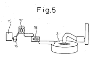
- FIG. 5 a typical example of equipment configuration in the case of using an extraction forming machine, which is the most economical method as a process of excluding a dryer 2, is shown in Figure 5 .
- the methods for producing, drying and reducing compacts with this equipment are explained hereunder.
- raw material comprising metal oxide powder in the state of containing not less than 50 mass % water and pulverized reducing agent mainly composed of carbon is mixed and contained in a mixing pit 15.
- the metal oxide raw material ore powder including iron ore powder, manganese ore powder, chromium ore powder, etc.
- dust from a refining furnace and sludge from a rolling process those being generated in the metal producing industry, and others are used.
- sludge generated in the metal producing industry is the most suitable raw material because it contains about 70% water by nature.
- the solid-liquid mixture of the raw material is stirred and mixed well in the mixing pit 15.
- the solid-liquid mixture is transported to a dehydrator 17 with a slurry transportation pump 16, dehydrated to the water content of 15 to 27 mass % with the dehydrator, and formed into water contained aggregates of the raw material mixture.
- a dehydrator of the type wherein solid-liquid mixture is poured on a filter cloth that moves in a circulatory manner and squeezed with a pair of press rolls installed above and under the filter cloth, a filter press, a centrifugal dehydrator or the like is preferably used.
- the produced water contained aggregates is fed to an extrusion forming machine 18 and formed into compacts while water is contained.
- the compacts 12 have a diameter of about 8 to 20 mm and a representative diameter of 5 to 21 mm.
- the compacts 12 is configured so that water vapor may be likely to be extracted and thus the compacts may be hardly exploded in a rotary furnace 3.
- the porosity of the compacts 12 is controlled to 40 to 55%.
- the compacts 12 are fed to the rotary furnace 3 in the state of containing 15 to 27 mass % water.
- the compacts 12 are charged on a hearth 6 and thereafter dried in a drying zone 5 while the heating rate is controlled. Specifically, the compacts 12 are dried for 60 to 300 sec. at 600°C to 1,170°C.
- the compacts 12 from which water has been removed (dried) in the drying zone 5 move together with the hearth 6 in the furnace, are transferred to a reducing zone 7 having a high temperature, are subjected to reducing reaction actively at the time when the temperature of the compacts 12 exceeds 1,100°C, and most of the metal oxide of the compacts 12 is transformed into metal.
- the reduced compacts 13 are discharged from the hearth 6 with a screw discharger 8.
- the reduced compacts 13 thus produced are used as raw material for a metal reducing furnace or a metal refining furnace including an electric arc furnace or a blast furnace.
- Table 1 shows the results of Examples 1 to 3 obtained by drying compacts in an exclusive dryer 2 and thereafter incinerating and refining them in a rotary furnace 3.
- the treatment conditions of Examples 1 to 3 are as follows.
- the raw material powder comprised 63 mass % iron oxide and 15 mass % carbon and the average diameter of the powder was 11 microns.
- the compacts were formed from the powder with three kinds of devices; a pan-type pelletizer, a briquette forming machine and an extraction forming machine.
- the compacts produced by those methods were dried in the drying furnace 2 by controlling the water evaporation rate to not more than V (critical evaporation rate) and the heat supply rate to not more than Hin (critical heat supply rate). Further, the compacts after dried were incinerated and reduced in the rotary furnace 3. In any of the reducing treatments, the reducing time was 15 min. and the atmospheric temperature during the reducing was 1,320°C. In contrast, in the case of Comparative Examples, the same compacts as Examples 1 to 3 were used and subjected to incineration and reduction. However, they were dried by controlling the water evaporation rate to more than V (critical evaporation rate) or the heat supply rate to more than Hin (critical heat supply rate). The other conditions were identical to Examples 1 to 3. The results are shown in Table 2.
- a powdering ratio was defined by the ratio of the mass (mass %) of the compacts less than 5 mm in size obtained by sieving the compacts after being dried with a sieve 5 mm in mesh to the total mass of the compacts before sieving.
- a bulk yield of reduced products was defined by the ratio of the mass (mass %) of the compacts not less than 5 mm in size obtained by sieving the compacts after reduced with a sieve 5 mm in mesh to the total mass of the compacts before sieving
- an iron metallization ratio was defined by the ratio of the mass (mass %) of the metallic iron in the reduced products to the total iron mass.
- Example 1 Example 2
- Example 3 Forming machine Pan-type pelletizer Briquette forming machine Extrusion forming machine Compact Spherical Almond-shaped Columnar Size * ) (mm) 15 18 17 Porosity (%) 27% 33% 47% Water content (mass %) 11.5% 14.6% 21.2%
- Critical value of drying V value (g/kg ⁇ sec.) 1.5 1.8 3.9
- Hin value (kw/kg) 4.0 5.0 10.7 Drying result Actual water evaporation rate (g/kg ⁇ sec.) 0.77 1.3
- Actual heat supply rate (kw/kg) 2.1 3.7 7.5 Evaluation of drying state Existence of explosion None None None None None None None Powdering ratio (mass %) 3.9% 2.6% 3.3%
- Result of reduced product Iron metallization ratio (mass %) 85% 88% 88% Bulk product yield (mass %) 92% 88% 86% *) Cube root of compact volume
- Example 1 shows the results of the operation in the case of using compacts a produced with a pan-type pelletizer and having a porosity of 27%, which is relatively dense.
- the values of V and Hin computed from the size and the porosity of the compacts were 1.5 g/kg/sec. and 4.0 kw/kg, respectively. Meanwhile, the actual water evaporation rate and heat supply rate were 0.77 g/kg/sec. and 2.1 kw/kg, respectively. Therefore, explosion was not observed since the water evaporation rate was lower than the critical value and, further, the powdering from the compact surfaces was as low as 3.9%. As a result of reducing the compacts, the iron metallization ratio was as high as 85% and the bulk yield of the products was as good as 92%.
- Example 2 compacts produced with a briquette forming machine and having a porosity of 33% were used.
- the values of V and Hin computed from the size and the porosity of the compacts were 1.8 g/kg/sec. and 5.0 kw/kg, respectively. Meanwhile, the actual water evaporation rate and heat supply rate were as low as 1.3 g/kg/sec. and 3.7 kw/kg, respectively. Therefore, explosion was not observed and further the powdering from the compact surfaces was as low as 2.6%.
- the iron metallization ratio was as high as 88% and the bulk yield of the products was as good as 88%.
- Example 3 compacts produced with an extrusion forming machine and having a porosity of 47%, which is a low packing density, were used.
- the values of V and Hin computed from the size and the porosity of the compacts were 3.9 g/kg/sec. and 10.7 kw/kg, respectively. Meanwhile, the actual water evaporation rate and heat supply rate were as low as 2.7 g/kg/sec. and 7.5 kw/kg, respectively. Therefore, explosion was not observed and further the powdering from the compact surfaces was as low as 3.3%.
- the iron metallization ratio was as high as 88% and the bulk yield of the products was as good as 86%.
- Comparative Examples 1 to 3 the results were obtained by drying the same compacts as Examples 1 to 3 under the conditions deviating from those stipulated in the present invention and then reducing them.
- the water evaporation rate and the heat supply rate of the compacts were larger than the critical values respectively, the compacts were not dried properly.
- the compacts exploded and 76 to 88% of the compacts were decomposed into powder. As a result, the reduction operation was not properly carried out in the rotary furnace 3.
- Comparative Example 3 the results were obtained by drying compacts produced with an extrusion forming machine and having a high porosity and then reducing them.
- Example 3 shows the results of Examples 4 to 6 that are the examples of the operations carried out by the method wherein the compacts are dried in the rotary furnace 3 as shown in Figure 3 or 4 .
- the treatment conditions of Examples 4 to 6 are as follows.
- the raw material powder comprised 63 mass % iron oxide and 15 mass % carbon and the average diameter of the powder was 11 microns, which were the same as Examples 1 to 3.
- the compacts were formed likewise from the powder with three kinds of devices; a pan-type pelletizer, a briquette forming machine and an extraction forming machine.
- the water evaporation rate was controlled to not more than V (critical evaporation rate) and the heat supply rate to not more than Hin (critical heat supply rate).
- Example 4 Forming machine Pan-type pelletizer Briquette forming machine Extrusion forming machine Compact Spherical Almond-shaped Columnar Size *) (mm) 17 20 20 Porosity (vol. %) 27% 33% 47% Water content (mass %) 11.5% 14.6% 21.2% Drying zone of rotary furnace Structure of drying zone Reducing zone and drying zone are separated by exhaust gas discharging flue, ceiling is equipped with cooling means.
- Reducing zone and drying zone are separated by exhaust gas discharging flue, heating burners are installed Reducing zone and drying zone are separated by exhaust gas discharging flue, heating burners are installed Drying zone resident time (sec.) 200 160 100 Drying zone temperature 250 - 450°C 450 - 750°C 700 - 950°C Critical value of drying V value (g/kg ⁇ sec.) 1.3 1.6 3.3 Hin value (kw/kg) 3.5 4.5 9.1 Drving result Actual water evaporation rate (g/kg ⁇ sec.) 0.67 1.1 2.6 Actual heat supply rate (kw/kg) 1.8 3.1 7.5 Evaluation of drying state Existence of explosion None None None None None None Powdering ratio (mass %) 5.1% 5.9% 3.1% Result of reduced product Iron metallization ratio (mass %) 84% 81% 83% Bulk product yield (mass %) 94% 91% 95% *) Cube root of compact volume
- Example 4 is an example of the operation in the case of using spherical compacts produced with a pan-type pelletizer and having a porosity of 27%, which is relatively dense.
- the compacts have a low porosity and they explode easily when a water evaporation rate increases. Therefore, the atmospheric temperature in the drying zone 5 was controlled in the range from the lowest temperature of 250°C to the highest temperature of 450°C.
- the exhaust gas discharging flue 10 was installed between the drying zone 5 and the reducing zone 7 so that exhaust gas generated in the reducing zone 7 might not flow into the drying zone 5.
- the ceiling between the screw discharger 8 and the compact feeder 4 at the compact supply portion and parts of the ceiling in the drying zone 5 were equipped with water cooling means.
- the heat supply rate to the compacts could be reduced to 1.8 kw/kg, lower than Hin, and the water evaporation rate could also be reduced to 0.67 g/kg/sec., lower than V.
- the reducing treatment was also good and the powdering ratio was as low as 5.1% and the iron metallization ratio and the bulk product yield were high.
- Example 5 is an example of the operation in the case of using almond-shaped compacts produced with a briquette forming machine and having a porosity of 33%.
- the heat supply rate to the compacts was controlled to not more than Hin and the water evaporation rate was also controlled to not more than V so that the compacts might not cause the problems of the explosion or powdering.
- the exhaust gas discharging flue 10 was installed between the drying zone 5 and the reducing zone 7 so that exhaust gas generated in the reducing zone 7 might not flow into the drying zone 5.
- the amount of the water vapor generated from the compacts is relatively large and, therefore, the atmospheric temperature in the drying zone 5 lowers in excess of the target temperature in some cases.
- Example 6 is an example of the operation in the case of using columnar compacts produced with an extrusion forming machine and having a porosity of 47%.
- the heat supply rate to the compacts was controlled to not more than Hin and the water evaporation rate was also controlled to not more than V so that the compacts might not cause the problems of the explosion or powdering.
- the exhaust gas discharging flue 10 was installed between the drying zone 5 and the reducing zone 7, similarly to Example 5.
- the compacts of Example 6 contained a large amount of water and therefore the atmospheric temperature in the drying zone 5 dropped considerably due to the water vapor.
- Example 7 iron oxide and sludge containing carbon in a quantity generated in the processes of the steelmaking industry were used as the raw material and formed into compacts and the compacts were reduced by using the reducing equipment shown in Figure 5 .
- the raw material used in the operation had the average diameter of 9 microns and the water content of 21%.
- the porosity of the compacts produced with the extraction forming machine was 44% and the representative diameter thereof was 15 mm.
- the temperature of the drying zone 5 was controlled in the range from 890°C to 1,020°C and the length of the drying zone 5 was 150 sec. in terms of the transit time of the hearth 6. As a result of drying the compacts under those conditions, the problems of the explosion and powdering of the compacts did not occur.
- the highest temperature in the reducing zone 7 was 1,300°C and the reducing time was 13 min.
- the bulk yield of the reduced product of Example 7 was as high as 91% and the iron loss to dust was as low as 1.7%. Further, the iron metallization ratio was 88% and thus the reduction was also good.
- the present invention makes it possible to dry compacts, made of powder containing water, properly and to reduce metal oxide economically in a rotary hearth reduction process. Further, the present invention is effective for the processing of sludge comprising metal oxide containing water in quantity and dust containing carbon.
Landscapes
- Engineering & Computer Science (AREA)
- Chemical & Material Sciences (AREA)
- Mechanical Engineering (AREA)
- General Engineering & Computer Science (AREA)
- Manufacturing & Machinery (AREA)
- Materials Engineering (AREA)
- Metallurgy (AREA)
- Organic Chemistry (AREA)
- Manufacture And Refinement Of Metals (AREA)
- Manufacture Of Iron (AREA)
Claims (14)
- Verfahren zum Trocknen von Formkörpern, dadurch gekennzeichnet, dass Formkörper, die Metalloxidpulver, Kohlenstoffpulver und auch Wasser in einem Masseprozentsatz von mindestens dem 0,2-fachen der in Prozent angegebenen Porosität enthalten, getrocknet werden durch Steuern der Verdampfungsgeschwindigkeit von in den Formkörpern enthaltenem Wasser auf höchstens den Wert V in der nachstehenden Festlegung:

wobei V eine kritische Wasserverdampfungsgeschwindigkeit (eine Wasserverdampfungsgeschwindigkeit pro Kilogramm Formkörper-Trockenmasse (g/kg/s)), D eine Kubikwurzel des Volumens eines Formkörpers (mm) und P eine Porosität (-)bezeichnet, oder durch Steuern der Rate der Wärmezufuhr zu den Formkörpern auf höchstens den Wert Hin in der nachstehenden Festlegung:
wobei Hin eine kritische Wärmezufuhrrate (eine Wärmezufuhrrate pro Kilogramm Formkörper-Trockenmasse (kW/kg)), D eine Kubikwurzel des Volumens eines Formkörpers (mm) und P eine Porosität (-)bezeichnet. - Verfahren zum Trocknen von Formkörpern nach Anspruch 1, dadurch gekennzeichnet, dass Formkörper mit einer Kubikwurzel des Volumens von 5 bis 21 mm und einer Porosität von 22 bis 32 % aus dem Zustand getrocknet werden, in dem mindestens 4,4 Masse-% Wasser in den Formkörpern enthalten ist, indem die Wasserverdampfungsgeschwindigkeit in den Formkörpern auf höchstens 0,7 g/s pro Kilogramm Formkörper-Trockenmasse gesteuert wird.
- Verfahren zum Trocknen von Formkörpern nach Anspruch 1, dadurch gekennzeichnet, dass Formkörper mit einer Kubikwurzel des Volumens von 5 bis 21 mm und einer Porosität von 22 bis 32 % aus dem Zustand getrocknet werden, in dem mindestens 4,4 Masse-% Wasser in den Formkörpern enthalten ist, indem die Wärmezufuhrrate zu den Formkörpern auf höchstens 1,9 kW pro Kilogramm Formkörper-Trockenmasse gesteuert wird.
- Verfahren zum Trocknen von Formkörpern nach Anspruch 1, dadurch gekennzeichnet, dass Formkörper mit einer Kubikwurzel des Volumens von 5 bis 21 mm und einer Porosität über 32 bis 40 % aus dem Zustand getrocknet werden, in dem mindestens 6,4 Masse-% Wasser in den Formkörpern enthalten ist, indem die Wasserverdampfungsgeschwindigkeit in den Formkörpern auf höchstens 1,3 g/s pro Kilogramm Formkörper-Trockenmasse gesteuert wird.
- Verfahren zum Trocknen von Formkörpern nach Anspruch 1, dadurch gekennzeichnet, dass Formkörper mit einer Kubikwurzel des Volumens von 5 bis 21 mm und einer Porosität über 32 bis 40 % aus dem Zustand getrocknet werden, in dem mindestens 6,4 Masse-% Wasser in den Formkörpern enthalten ist, indem die Wärmezufuhrrate zu den Formkörpern auf höchstens 3,5 kW pro Kilogramm Formkörper-Trockenmasse gesteuert wird.
- Verfahren zum Trocknen von Formkörpern nach Anspruch 1, dadurch gekennzeichnet, dass Formkörper mit einer Kubikwurzel des Volumens von 5 bis 21 mm und einer Porosität über 40 bis 55 % aus dem Zustand getrocknet werden, in dem mindestens 8 Masse-% Wasser in den Formkörpern enthalten ist, indem die Wasserverdampfungsgeschwindigkeit in den Formkörpern auf höchstens 2,3 g/s pro Kilogramm Formkörper-Trockenmasse gesteuert wird.
- Verfahren zum Trocknen von Formkörpern nach Anspruch 1, dadurch gekennzeichnet, dass Formkörper mit einer Kubikwurzel des Volumens von 5 bis 21 mm und einer Porosität über 40 bis 55 % aus dem Zustand getrocknet werden, in dem mindestens 8 Masse-% Wasser in den Formkörpern enthalten ist, indem die Wärmezufuhrrate zu den Formkörpern auf höchstens 6,2 kW pro Kilogramm Formkörper-Trockenmasse gesteuert wird.
- Verfahren zum Trocknen von Formkörpern nach einem der Ansprüche 1 bis 7, gekennzeichnet durch Verwenden von Pulver, das aus einem Metallherstellungsverfahren abgeleitetes Metalloxid und Kohlenstoff einzeln oder in Mischung enthält, als das Pulver aus einem Metalloxid und Kohlenstoff.
- Verfahren zum Reduzieren von Metalloxid, gekennzeichnet durch Brennen und Reduzieren von Formkörpern, die durch ein Verfahren nach einem der Ansprüche 1 bis 8 getrocknet wurden, bei mindestens 1100 °C in einem Drehherdofen, wobei Pulver aus Metalloxid und Kohlenstoff enthaltende Formkörper auf die Oberseite eines Drehringherds aufgegeben und durch Gasverbrennungswärme im oberen Innenraum des Ofens gebrannt und reduziert werden.
- Verfahren zum Reduzieren von Metalloxid, dadurch gekennzeichnet, dass nach Trocknen von Formkörpern durch ein Verfahren nach einem der Ansprüche 1 bis 8 in einem Drehherdofen Pulver aus Metalloxid und Kohlenstoff enthaltende Formkörper auf die Oberseite eines Drehringherds aufgegeben und durch Gasverbrennungswärme im oberen Innenraum des Ofens gebrannt und reduziert werden, wobei die Formkörper bei mindestens 1100 °C in dem Ofen nacheinander gebrannt und reduziert werden.
- Drehherd-Metallreduktionsofen (3), der mit einer Trocknungszone (5) und einer Reduktionszone (7) versehen ist, wobei Pulver aus Metalloxid und Kohlenstoff enthaltende Formkörper auf die Oberseite eines Drehringherds (3) aufgegeben und durch Gasverbrennungswärme im oberen Innenraum des Ofens gebrannt und reduziert und die reduzierten Formkörper abgeführt werden, dadurch gekennzeichnet, dass der Ofen mit einer Einrichtung zum Kühlen des Herds zwischen dem Abschnitt, in dem die reduzierten Formkörper abgeführt werden, und dem Abschnitt, in dem die Rohmaterial-Formkörper zugeführt werden, sowie mit Heizbrennern (11) auf den Seitenwänden der Trocknungszone ausgestattet ist, wobei der Bereich des Drehofens vom Abschnitt, in dem die Rohmaterial-Pulverformkörper zugeführt werden, bis zu einem in Drehrichtung 30 bis 130 Grad von diesem Abschnitt entfernten Abschnitt als Trocknungszone (5) der Formkörper verwendet wird, und ein Abgasabzug (10) an der Grenze zwischen der Trocknungszone (5) und der Reduktionszone (7) eingebaut ist.
- Drehherd-Metallreduktionsofen nach Anspruch 11, dadurch gekennzeichnet, dass: der Abgasabzug (10) an einem in Drehrichtung 30 bis 130 Grad vom Abschnitt, in dem die Rohmaterial-Formkörper zugeführt werden, entfernten Abschnitt eingebaut ist; und der Bereich vom Abschnitt, in dem die Rohmaterial-Formkörper zugeführt werden, bis zum Abschnitt, in dem der Abgasabzug (10) eingebaut ist, als Trocknungszone verwendet wird.
- Drehherd-Metallreduktionsofen nach Anspruch 11, dadurch gekennzeichnet, dass: eine Trennwand (14) mit einem Spalt zwischen ihrem unteren Ende und dem Drehherd in dem Abschnitt eingebaut ist, der 30 bis 130 Grad vom Abschnitt, in dem die Rohmaterial-Formkörper zugeführt werden, in Drehrichtung entfernt ist; und der Bereich vom Abschnitt, in dem die Rohmaterial-Formkörper zugeführt werden, bis zum Abschnitt, in dem die Trennwand (14) eingebaut ist, als Trocknungszone (5) verwendet wird.
- Drehherd-Metallreduktionsofen nach einem der Ansprüche 11 bis 13, dadurch gekennzeichnet, dass er mit einer Wasserkühleinrichtung an der Decke und Teilen der Seitenwände zwischen dem Abschnitt, in dem die reduzierten Formkörper abgeführt werden, und der Trocknungszone (5) im Ofen ausgestattet ist.
Priority Applications (1)
| Application Number | Priority Date | Filing Date | Title |
|---|---|---|---|
| EP11160043A EP2341153A1 (de) | 2001-09-27 | 2002-04-01 | Verfahren zum Trocknen eines metalloxidhaltigen Presskörpers, Verfahren zur Metalloxidreduktion und Drehherd-Metallreduktionsofen |
Applications Claiming Priority (3)
| Application Number | Priority Date | Filing Date | Title |
|---|---|---|---|
| JP2001296084 | 2001-09-27 | ||
| JP2001296084A JP3631709B2 (ja) | 2000-10-03 | 2001-09-27 | 酸化金属の還元方法 |
| PCT/JP2002/003273 WO2003031659A1 (en) | 2001-09-27 | 2002-04-01 | Method for drying molding containing oxidized metal, method for reducing oxidized metal and rotary hearth type metal reduction furnace |
Related Child Applications (1)
| Application Number | Title | Priority Date | Filing Date |
|---|---|---|---|
| EP11160043.3 Division-Into | 2011-03-28 |
Publications (3)
| Publication Number | Publication Date |
|---|---|
| EP1439236A1 EP1439236A1 (de) | 2004-07-21 |
| EP1439236A4 EP1439236A4 (de) | 2008-09-03 |
| EP1439236B1 true EP1439236B1 (de) | 2012-12-05 |
Family
ID=19117395
Family Applications (2)
| Application Number | Title | Priority Date | Filing Date |
|---|---|---|---|
| EP02708751A Expired - Lifetime EP1439236B1 (de) | 2001-09-27 | 2002-04-01 | Verfahren zum trocknen eines oxidiertes metall enthaltenden formkörpers, verfahren zum reduzieren von oxidiertem metall und drehherd-metallreduktionsofen |
| EP11160043A Withdrawn EP2341153A1 (de) | 2001-09-27 | 2002-04-01 | Verfahren zum Trocknen eines metalloxidhaltigen Presskörpers, Verfahren zur Metalloxidreduktion und Drehherd-Metallreduktionsofen |
Family Applications After (1)
| Application Number | Title | Priority Date | Filing Date |
|---|---|---|---|
| EP11160043A Withdrawn EP2341153A1 (de) | 2001-09-27 | 2002-04-01 | Verfahren zum Trocknen eines metalloxidhaltigen Presskörpers, Verfahren zur Metalloxidreduktion und Drehherd-Metallreduktionsofen |
Country Status (6)
| Country | Link |
|---|---|
| US (1) | US6993855B2 (de) |
| EP (2) | EP1439236B1 (de) |
| KR (1) | KR100633871B1 (de) |
| CN (1) | CN100455679C (de) |
| TW (1) | TW522170B (de) |
| WO (1) | WO2003031659A1 (de) |
Families Citing this family (3)
| Publication number | Priority date | Publication date | Assignee | Title |
|---|---|---|---|---|
| US7879132B2 (en) | 2002-09-13 | 2011-02-01 | Nippon Steel Corporation | Method for reduction treatment of metal oxide or ironmaking waste and method for concentration and recovery zinc and/or lead |
| JP4707407B2 (ja) * | 2005-02-18 | 2011-06-22 | Ntn株式会社 | 製鋼ダスト固形化物およびその製造方法 |
| CN101224912B (zh) * | 2008-01-25 | 2011-03-23 | 广州普得环保设备有限公司 | 一种污泥干燥的方法 |
Family Cites Families (18)
| Publication number | Priority date | Publication date | Assignee | Title |
|---|---|---|---|---|
| US3759693A (en) * | 1969-08-18 | 1973-09-18 | Kobe Steel Ltd | Method of producing reduced iron ore pellets |
| JPS5261108A (en) | 1975-11-14 | 1977-05-20 | Sumitomo Metal Ind Ltd | Dezincifition method of blast furnace dust and its apparatus |
| CA1333220C (fr) * | 1989-09-28 | 1994-11-29 | Piezo Ceram Electronique | Four annulaire a sole tournante pour conformer a un profil voulu l'une des faces d'ebauches de lentilles optiques par affaissement thermique et application de vide |
| US5186741A (en) * | 1991-04-12 | 1993-02-16 | Zia Patent Company | Direct reduction process in a rotary hearth furnace |
| US5730775A (en) | 1994-12-16 | 1998-03-24 | Midrex International B.V. Rotterdam, Zurich Branch | Method for rapid reduction of iron oxide in a rotary hearth furnace |
| BR9707133A (pt) * | 1996-11-11 | 1999-05-18 | Sumitomo Metal Ind | Processo para produzir ferro reduzido e metal quente a partir de óxidos de ferro finos e instalação para executar o processo |
| JP3439059B2 (ja) * | 1997-01-22 | 2003-08-25 | 三菱重工業株式会社 | 還元鉄製造装置 |
| JPH1112619A (ja) | 1997-06-26 | 1999-01-19 | Sumitomo Metal Ind Ltd | 還元鉄の製造方法 |
| JPH1112621A (ja) | 1997-06-27 | 1999-01-19 | Sumitomo Metal Ind Ltd | 還元鉄製造原料の装入方法および装置 |
| JP4022941B2 (ja) | 1997-06-27 | 2007-12-19 | 住友金属工業株式会社 | 還元鉄製造原料の成形方法 |
| US5924861A (en) * | 1997-08-28 | 1999-07-20 | Maumee Research & Engineering, Incorporated | Furnace discharge assembly |
| TW495552B (en) * | 1997-12-18 | 2002-07-21 | Kobe Steel Ltd | Method of producing reduced iron pellets |
| JP3403091B2 (ja) | 1998-09-30 | 2003-05-06 | 三菱重工業株式会社 | 回転床式還元炉による湿潤ペレットの還元方法および回転床式還元炉 |
| JPH11337264A (ja) | 1998-05-27 | 1999-12-10 | Daido Steel Co Ltd | 回転炉床炉 |
| JPH11335746A (ja) | 1998-05-27 | 1999-12-07 | Daido Steel Co Ltd | ペレット供給装置 |
| JP2001032005A (ja) | 1999-07-21 | 2001-02-06 | Nippon Steel Corp | 還元用回転炉床法の操業方法 |
| CN1262676C (zh) | 1999-12-13 | 2006-07-05 | 新日本制铁株式会社 | 氧化铁的还原设备,还原铁和铁合金的制造方法及还原炉原料的成形体 |
| JP3579652B2 (ja) | 1999-12-13 | 2004-10-20 | 新日本製鐵株式会社 | 酸化金属の還元設備 |
-
2002
- 2002-04-01 EP EP02708751A patent/EP1439236B1/de not_active Expired - Lifetime
- 2002-04-01 KR KR1020047004599A patent/KR100633871B1/ko not_active Expired - Fee Related
- 2002-04-01 US US10/491,033 patent/US6993855B2/en not_active Expired - Lifetime
- 2002-04-01 CN CNB028187423A patent/CN100455679C/zh not_active Expired - Lifetime
- 2002-04-01 EP EP11160043A patent/EP2341153A1/de not_active Withdrawn
- 2002-04-01 WO PCT/JP2002/003273 patent/WO2003031659A1/ja not_active Ceased
- 2002-04-02 TW TW091106598A patent/TW522170B/zh not_active IP Right Cessation
Also Published As
| Publication number | Publication date |
|---|---|
| US6993855B2 (en) | 2006-02-07 |
| WO2003031659A1 (en) | 2003-04-17 |
| US20040237335A1 (en) | 2004-12-02 |
| EP1439236A1 (de) | 2004-07-21 |
| KR100633871B1 (ko) | 2006-10-13 |
| EP2341153A1 (de) | 2011-07-06 |
| EP1439236A4 (de) | 2008-09-03 |
| CN100455679C (zh) | 2009-01-28 |
| CN1558959A (zh) | 2004-12-29 |
| KR20040033327A (ko) | 2004-04-21 |
| TW522170B (en) | 2003-03-01 |
Similar Documents
| Publication | Publication Date | Title |
|---|---|---|
| EP0924304B1 (de) | Verfahren zur Herstellung reduzierter Eisenpellets | |
| KR100530815B1 (ko) | 환원로용 산화 금속 함유 미가공 팰릿, 그 제조 방법, 그환원 방법 및 환원 설비 | |
| KR101022447B1 (ko) | 분환원철 및 소성부원료를 고온 괴성화하는 용철제조장치및 그 용철제조방법 | |
| EP3892744B1 (de) | Sintererzherstellungsverfahren | |
| KR100607628B1 (ko) | 회전 노상식 환원로에서의 환원철 성형체의 제조 방법 및환원철 성형체 및 이를 이용한 선철의 제조 방법 | |
| JPS6223944A (ja) | 酸化ニッケル鉱石からフェロニッケルルッペを製造する方法 | |
| US3313617A (en) | Iron-containing flux material for steel-making process | |
| EP2100978B1 (de) | Verfahren zur Reduktionsbehandlung von Stahlherstellungabfall und Verfahren | |
| KR100673785B1 (ko) | 산화 금속 환원용 설비와 그 조작 방법 및 환원로용 원재료의 성형물 | |
| KR101492783B1 (ko) | 페로크롬의 제조 방법 | |
| US6993855B2 (en) | Method for drying compact containing metal oxide, method for reducing metal oxide, and rotary-hearth-type metal reducing furnace | |
| CN1325666C (zh) | 制造铁水的设备及其使用方法 | |
| JP3631709B2 (ja) | 酸化金属の還元方法 | |
| JP4264188B2 (ja) | 酸化金属の還元方法 | |
| CN1125839A (zh) | 铁矿石烧结造块工艺方法 | |
| JP3579652B2 (ja) | 酸化金属の還元設備 | |
| JP2002206119A (ja) | 酸化金属の還元方法、および、酸化金属の還元設備 | |
| JP3504870B2 (ja) | 鉄鉱石ペレット原料の事前処理方法 | |
| CN213611872U (zh) | 防火材制作结构 | |
| CN112853088B (zh) | 一种球团链箅机散料综合处理的方法及其处理系统 | |
| CN113834342B (zh) | 一种鼓风式烧结余热回收造块装置及方法 | |
| JP4935384B2 (ja) | 還元金属の製造方法 | |
| GB1601351A (en) | Manufacture of elongate workpiece from pelleted material |
Legal Events
| Date | Code | Title | Description |
|---|---|---|---|
| PUAI | Public reference made under article 153(3) epc to a published international application that has entered the european phase |
Free format text: ORIGINAL CODE: 0009012 |
|
| 17P | Request for examination filed |
Effective date: 20040416 |
|
| AK | Designated contracting states |
Kind code of ref document: A1 Designated state(s): AT BE CH CY DE DK ES FI FR GB GR IE IT LI LU MC NL PT SE TR |
|
| AX | Request for extension of the european patent |
Extension state: AL LT LV MK RO SI |
|
| A4 | Supplementary search report drawn up and despatched |
Effective date: 20080801 |
|
| RIC1 | Information provided on ipc code assigned before grant |
Ipc: F27B 9/16 20060101ALI20080728BHEP Ipc: C21B 13/10 20060101AFI20030424BHEP |
|
| REG | Reference to a national code |
Ref country code: DE Ref legal event code: 8566 |
|
| 17Q | First examination report despatched |
Effective date: 20090304 |
|
| R17C | First examination report despatched (corrected) |
Effective date: 20090319 |
|
| GRAP | Despatch of communication of intention to grant a patent |
Free format text: ORIGINAL CODE: EPIDOSNIGR1 |
|
| GRAS | Grant fee paid |
Free format text: ORIGINAL CODE: EPIDOSNIGR3 |
|
| GRAA | (expected) grant |
Free format text: ORIGINAL CODE: 0009210 |
|
| RIN1 | Information on inventor provided before grant (corrected) |
Inventor name: TAKAHASHI, SHIGEKI Inventor name: ABE, YOICHI Inventor name: YAMAMOTO, TAKASHI Inventor name: IBARAKI, TETSUHARU Inventor name: NAGAI, KAZUNORI |
|
| AK | Designated contracting states |
Kind code of ref document: B1 Designated state(s): FR IT |
|
| RAP2 | Party data changed (patent owner data changed or rights of a patent transferred) |
Owner name: NIPPON STEEL & SUMITOMO METAL CORPORATION |
|
| PLBE | No opposition filed within time limit |
Free format text: ORIGINAL CODE: 0009261 |
|
| STAA | Information on the status of an ep patent application or granted ep patent |
Free format text: STATUS: NO OPPOSITION FILED WITHIN TIME LIMIT |
|
| 26N | No opposition filed |
Effective date: 20130906 |
|
| REG | Reference to a national code |
Ref country code: FR Ref legal event code: PLFP Year of fee payment: 15 |
|
| REG | Reference to a national code |
Ref country code: FR Ref legal event code: PLFP Year of fee payment: 16 |
|
| REG | Reference to a national code |
Ref country code: FR Ref legal event code: PLFP Year of fee payment: 17 |
|
| PGFP | Annual fee paid to national office [announced via postgrant information from national office to epo] |
Ref country code: IT Payment date: 20210310 Year of fee payment: 20 Ref country code: FR Payment date: 20210309 Year of fee payment: 20 |