EP1439257A2 - Machine à sécher avec consoles de fixation d'un moteur sur la base de la machine - Google Patents
Machine à sécher avec consoles de fixation d'un moteur sur la base de la machine Download PDFInfo
- Publication number
- EP1439257A2 EP1439257A2 EP03006011A EP03006011A EP1439257A2 EP 1439257 A2 EP1439257 A2 EP 1439257A2 EP 03006011 A EP03006011 A EP 03006011A EP 03006011 A EP03006011 A EP 03006011A EP 1439257 A2 EP1439257 A2 EP 1439257A2
- Authority
- EP
- European Patent Office
- Prior art keywords
- motor
- supporting
- motor fixing
- fixing brackets
- machine
- Prior art date
- Legal status (The legal status is an assumption and is not a legal conclusion. Google has not performed a legal analysis and makes no representation as to the accuracy of the status listed.)
- Withdrawn
Links
- 238000001035 drying Methods 0.000 title claims abstract description 77
- 238000007664 blowing Methods 0.000 claims description 11
- 238000010438 heat treatment Methods 0.000 claims description 10
- 230000003247 decreasing effect Effects 0.000 claims description 5
- 230000000149 penetrating effect Effects 0.000 claims description 4
- 230000003014 reinforcing effect Effects 0.000 claims description 4
- 238000010276 construction Methods 0.000 description 2
- 238000007792 addition Methods 0.000 description 1
- 239000000853 adhesive Substances 0.000 description 1
- 230000001070 adhesive effect Effects 0.000 description 1
- 238000012986 modification Methods 0.000 description 1
- 230000004048 modification Effects 0.000 description 1
- 238000006467 substitution reaction Methods 0.000 description 1
- 238000005406 washing Methods 0.000 description 1
Images






Classifications
-
- D—TEXTILES; PAPER
- D06—TREATMENT OF TEXTILES OR THE LIKE; LAUNDERING; FLEXIBLE MATERIALS NOT OTHERWISE PROVIDED FOR
- D06F—LAUNDERING, DRYING, IRONING, PRESSING OR FOLDING TEXTILE ARTICLES
- D06F58/00—Domestic laundry dryers
- D06F58/02—Domestic laundry dryers having dryer drums rotating about a horizontal axis
- D06F58/04—Details
- D06F58/08—Driving arrangements
-
- D—TEXTILES; PAPER
- D06—TREATMENT OF TEXTILES OR THE LIKE; LAUNDERING; FLEXIBLE MATERIALS NOT OTHERWISE PROVIDED FOR
- D06F—LAUNDERING, DRYING, IRONING, PRESSING OR FOLDING TEXTILE ARTICLES
- D06F37/00—Details specific to washing machines covered by groups D06F21/00 - D06F25/00
- D06F37/20—Mountings, e.g. resilient mountings, for the rotary receptacle, motor, tub or casing; Preventing or damping vibrations
- D06F37/206—Mounting of motor
Definitions
- the present invention relates to a drying machine for drying clothes, etc., and more particularly to a drying machine having improved motor fixing brackets for fixing a motor securely to a base in the drying machine.
- a drying machine for clothes generally supplies air heated by a heater into a drum, in which clothes to be dried are put, to dry the clothes.
- Such a drying machine may be used independently only for drying the clothes, or incorporated with a laundry machine for washing and drying the clothes at one time.
- Drying machines are generally classified into an exhausting-type drying machine and a condensing-type drying machine.
- the exhausting-type drying machine discharges humid air used to dry clothes to the outside, while the condensing-type drying machine condenses moisture laden in humid air used to dry clothes by heat exchange with outside air to produce low humidity air, and supplies the low humidity air to the clothes to be dried.
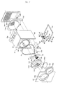
- Fig. 1 is an exploded perspective view of the conventional drying machine
- Fig. 2 is a sectional view showing the interior of the drying machine.
- the conventional drying machine includes a base 2, and a casing 10 placed on the base 2.
- the casing 10 has a clothes inlet 10a formed in the front part of the casing 10, and a door 10b pivotably attached to the casing 10.
- the clothes inlet 10a also acts as a clothes outlet, through which dried clothes are withdrawn.
- a drum 20 In the casing 10 is rotatably placed a drum 20, in which clothes to be dried are put.
- the drying machine further includes a heater 24 attached to the base 2 for heating air, a guide duct 26 for guiding the air heated by the heater 24 into the drum 20, a fan 28 for generating the blowing force necessary to blow the air heated by the heater 24 into the drum and to discharge the air in the drum to the outside of the drying machine, a lint trap 30 with a filter 31 for purifying the air used to dry the clothes in the drum 20, a fan housing 32 communicating with the lint trap 30 and enclosing the fan 28, an exhaust duct 34 communicating with the fan housing 32 for guiding the air discharged by the fan 28 to the outside of the drying machine, and a motor 40 attached to the base 2 for rotating the drum 20 and the fan 28.
- a heater 24 attached to the base 2 for heating air
- a guide duct 26 for guiding the air heated by the heater 24 into the drum 20
- a fan 28 for generating the blowing force necessary to blow the air heated by the heater 24 into the drum and to discharge the air in the drum to the outside of the drying
- the casing 10 includes side panels 12 and 13, a front panel 14 attached to the front ends of the side panels 12 and 13, and a rear panel 16 attached to the rear ends of the side panels 12 and 13.
- the rear panel 16 has an air suction hole 16a formed therein, through which outdoor air is sucked into the drying machine, and a duct through hole 16b formed therein, through which the exhaust duct 34 is extended.
- the casing 10 further includes a top cover 18 attached to the top ends of the side panels 12 and 13, and a control panel 19 provided on the top cover 18.
- a front supporter 36 for rotatably supporting the front part of the drum 20.
- the front supporter 36 has a clothes inlet 36a formed at the center thereof, and an exhaust hole 36b communicating with an inlet hole 30a of the lint trap 30 formed at the lower part thereof.
- the clothes inlet 36 also acts as a clothes outlet, through which dried clothes are withdrawn.
- a rear supporter 38 for rotatably supporting the rear part of the drum 20.
- the rear supporter 38 has an inflow hole 38a communicating with the upper end of the guide duct 26 formed in the center thereof. Through the inflow hole 38a, the air heated by the heater 24 is introduced into the drum.
- the drum 20 is provided at the inner circumference thereof with vanes 21 for lifting the clothes.
- the motor 40 is provided at the front and rear ends thereof with shafts 41a and 41b, respectively.
- shafts 41a and 41b On the shaft 41a, which is provided at the front end of the motor 40, is mounted the fan 28.
- a belt 22 is provided around the shaft 41b, which is provided at the rear end of the motor 40, and the drum 20, and serves to transfer the drive force of the motor 40 to the drum 20.
- the motor 40 is placed on a supporting member 4, which is attached to the base 2. To the supporting member 4 are fixedly attached motor fixing brackets 47 and 48 by means of bolts 42. The motor 40 is fixed tightly between the supporting member 4 and the motor fixing brackets 47 and 48.
- Clothes to be dried are put into the drum 20, and the door 10b is closed to operate the drying machine.
- the drum 20 and the fan 28 are rotated by the motor 40, and the heater 24 heats air. At this time, the clothes to be dried in the drum 20 are lifted by the vanes 21 and then dropped from the vanes 21.
- the air of high temperature and low humidity supplied into the drum 20 comes into contact with the clothes dropped from the vanes 21 to dry the clothes. After that, the air passes through the filter 31, and is exhausted outside the drying machine via the lint trap 30, the fan housing 32, and the exhaust duct 34 in turn.
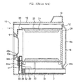
- Fig. 3 is a perspective view, partially cut away, of the conventional drying machine
- Fig. 4 is a cross sectional view taken along line A-A of Fig. 3
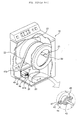
- Fig. 5 is a front view of the conventional drying machine showing a motor and motor fixing brackets disposed in the drying machine
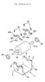
- Fig. 6 is an exploded perspective view of a motor and motor fixing brackets of the conventional drying machine.
- the motor 40 is provided at the front and rear parts thereof with hubs 43 and 44 for supporting the motor 40, respectively.
- hubs 43 and 44 On the outer circumferences of the hubs 43 and 44 are fitted vibration isolating rings 45 and 46, respectively, for absorbing the vibration.
- the supporting member 4 comprises a front supporting member 4a for supporting the front part of the motor 40, and a rear supporting member 4b for supporting the rear part of the motor 40.
- the front supporting member 4a is provided at the middle of the upper part thereof with a semicircular groove 5, in which the lower part of the vibration isolating ring 45 is placed.
- the rear supporting member 4b is provided at the middle of the upper part thereof with a semicircular groove 5, in which the lower part of the vibration isolating ring 46 is placed.
- At the right and left sides of the grooves 5 are formed fixing holes 6, into which the bolts 42 are screwed.
- the motor fixing brackets 47 and 48 are placed on the front and rear supporting members 4a and 4b in such a manner that the brackets 47 and 48 surround the upper parts of the vibration isolating rings 45 and 46.
- the motor fixing brackets 47 and 48 each have a semicircular curved part 49a, in which the upper part of each of the vibration isolating rings 45 and 46 is placed, and a fixing part 49c extended outwardly from the semicircular curved part 49a, which is placed on each of the front and rear supporting members 4a and 4b.
- fixing part 49c In the fixing part 49c are formed fixing holes 49b, into which the bolts 42 are screwed, at opposite sides of the semicircular curved part 49a.
- the motor fixing brackets 47 and 48 are placed on the front and rear supporting members 4a and 4b, and then the bolts 42 are screwed into the fixing holes 49b.
- the aforesaid conventional drying machine has drawbacks in that after the motor fixing brackets 47 and 48 are placed on the supporting member 4, the bolts 42 must be screwed into the fixing holes 49b and 6 in turn while the fixing holes 49b of the motor fixing brackets 47 and 48 are brought into line with the fixing holes 6 of the supporting member 4, with the result that the assembling position of the motor fixing brackets 47 and 48 and the supporting member 4 may be changed during fastening with the bolts 42, and that it is hard to assemble the motor fixing brackets quickly and easily.
- the motor fixing brackets 47 and 48 and the supporting member 4 must be fixed by means of the bolts 42 while the motor fixing brackets 47 and 48 are placed on the supporting member 4, with the result that the motor fixing brackets 47 and 49 do shake, which leads to loosening of the bolts.
- the drum 20 is disposed at the vicinity of the bolts 42, as shown in Figs. 3 and 5. Consequently, it is necessary to disassemble the drum 20 and the related parts before the bolts 42 are unscrewed when the motor 40 is to be repaired or replaced.
- the present invention has been made in view of the above problems, and it is an object of the present invention to provide a drying machine in which any vibration of a motor is prevented and attachment/detachment of the motor is easy and convenient.
- a drying machine comprising: a base; a casing disposed on the base; a drum rotatably placed inside the casing; a heater for heating air; a fan for blowing the air heated by the heater into the drum and for blowing the air passing through the drum outside the machine; a motor for rotating the fan and the drum; supporting members mounted on the base; and motor fixing brackets each including an insert part, through which the motor is inserted, and first and second supporting legs extending downwardly from the opposite ends of the insert part, the first and second supporting legs being engaged with the supporting members.
- a drying machine comprising: a base; a casing disposed on the base; a drum rotatably placed inside the casing; a condenser for condensing moisture laden in the air having passed through the drum by heat exchange between the air having passed through the drum and outside air; a fan for blowing the air having passed through the condenser into the drum; a heater for heating the air having passed through the condenser; a motor for rotating the fan and the drum; supporting members mounted on the base; and motor fixing brackets each including an insert part, through which the motor is inserted, and first and second supporting legs extending downwardly from the opposite ends of the insert part, the first and second supporting legs being engaged with the supporting members.
- Fig. 7 is an exploded perspective view of a preferred embodiment of a drying machine according to the present invention
- Fig. 8 is a perspective view, partially broken away, of the drying machine of the present invention
- Fig. 9 is a cross sectional view taken along line B-B of Fig. 8.
- the drying machine As shown in Figs. 7 to 9, the drying machine according to the present invention comprises a base 52, and a casing 54 placed on the base 52.
- the casing 52 has a clothes inlet 54a, which also acts as a clothes outlet, formed in the front central part of the casing 52, and a door 54b pivotably attached to the casing 54.
- a drum 60 In the casing 10 is rotatably placed a drum 60.
- a heater 62 attached to the base 52 for heating air
- a fan 64 for generating the blowing force necessary to blow the air heated by the heater 62 into the drum 60 and to discharge the air in the drum 60 to the outside of the drying machine
- a motor 70 attached to the base 52 for rotating the drum 60 and the fan 64
- supporting members 80 and 81 placed on the base 52
- motor fixing brackets 90 and 91 each have an insert part 86, through which the motor 70 is inserted, and first and second supporting legs 87 and 88 extending downwardly from the opposite sides of the insert part 86, respectively.
- the supporting members 80 and 81 are fitted between the first and second supporting legs 90 and 91.
- the drying machine further includes a guide duct 102 for guiding the air heated by the heater 62 into the drum 60, a lint trap 104 with a filter 103 for purifying the air used to dry the clothes in the drum 60, a fan housing 106 communicating with the lint trap 104 and enclosing the fan 64, and an exhaust duct 34 communicating with the fan housing 106 for guiding the air discharged by the fan 28 to the outside of the drying machine.
- the casing 54 includes side panels 55 and 56, a front panel 57 attached to the front ends of the side panels 55 and 56, and a rear panel 58 attached to the rear ends of the side panels 55 and 56.
- the rear panel 58 has an air suction hole 58a formed therein, through which outdoor air is sucked into the drying machine, and a duct through hole 58b formed therein, through which the exhaust duct 34 is extended.
- the casing 54 further includes a top cover 59 attached to the top ends of the side panels 55 and 56, and a control panel 59a provided on the top cover 59.
- a front supporter 112 for rotatably supporting the front part of the drum 60.
- the front supporter 112 has a clothes inlet 112a formed at the center thereof, through which clothes to be dried are thrown into the drum 60, and an exhaust hole 112b communicating with an inlet hole 104a of the lint trap 104 formed at the lower part thereof.
- the clothes inlet 112a also acts as a clothes outlet, through which dried clothes are withdrawn.
- the filter 103 is inserted into the lint trap 104 through the exhaust hole 112b of the front supporter 112 and the inlet hole 104 of the lint trap 104.
- a rear supporter 114 for rotatably supporting the rear part of the drum 60.
- the rear supporter 114 has an inflow hole 114a communicating with the upper end of the guide duct 102 formed in the center thereof. Through the inflow hole 114a, the air heated by the heater 62 is introduced into the drum 60.
- the drum 60 is provided at the inner circumference thereof with vanes 61 for lifting the clothes.
- the heater 62 comprises a hollow heater case and a heating coil arranged in the hollow heater case.
- the heating coil When current is applied to the heating coil, the heating coil generates heat, by which the inside of the heater case is heated as well as the heater case itself. As a result, the air having passed through the heater has high temperature and low humidity.
- the motor 70 is provided at the front and rear ends thereof with front and rear shafts 70a and 70b, respectively.
- a belt 71 is provided around the rear shaft 70b, which is provided at the rear end of the motor 70, and the drum 60.
- the motor 70 is supported in such a manner that the front and rear ends of the motor 70 are symmetrical with each other.
- a front hub 73 in such a manner that the front hub 73 is fitted on the outer circumference of the front shaft 70a.
- a rear hub 74 in such a manner that the rear hub 74 is fitted on the outer circumference of the rear shaft 70b.
- vibration isolating rings 75 and 76 On the outer circumferences of the front and rear hubs 73 and 74 are fitted vibration isolating rings 75 and 76 for absorbing the vibration from the motor 70, respectively.
- the supporting members 80 and 81 are placed on the base 52 in such a manner that the supporting members 80 and 81 are arranged apart from each other by the distance between the front and rear hubs 73 and 74.
- the front supporting member 80, one of the supporting members 80 and 81, is preferably formed integrally with the base 52.
- the rear supporting member 81, the other of the supporting members 80 and 81, is preferably formed integrally with the base 52.
- the supporting members 80 and 81 may be formed separately from the base 52 and attached to the base 52 by means of bolts or adhesives.
- the motor fixing brackets 90 and 91 comprise the front motor fixing bracket 90, which is engaged with the vibration isolating ring 75 on the front hub 73 and the front supporting member 80, and the rear motor fixing bracket 91, which is engaged with the vibration isolating ring 76 on the rear hub 74 and the rear supporting member 81.
- the motor 70 is fixed stably by means of the motor fixing brackets 90 and 91.
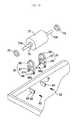
- Fig. 10 is a front view of the drying machine according to the present invention, showing that a motor and motor fixing brackets are disposed in the drying machine, and Fig. 11 is an exploded perspective view of the motor and the motor fixing brackets of the present invention.
- Each of the supporting members 80 and 81 is formed in such a manner that the width between the opposite sides of each of the supporting members 80 and 81 is increased upwardly.
- the supporting members 80 and 81 each have a fixing hole 84 penetrating the supporting member 80 or 81 from one side of the supporting member 80 or 81 to the other side of the supporting member 80 or 81, into which a fixing screw 82 is inserted, so that the supporting members 80 and 81 and the motor fixing brackets 90 and 91 fitted on the supporting members 80 and 81 are fixed tightly to each other by means of the fixing screws 82, respectively.
- the first and second supporting legs 87 and 88 of the motor fixing brackets 90 and 91 are formed in such a manner that the distance between the first and second supporting legs 87 and 88 is decreased downwardly. Consequently, the motor fixing brackets 90 and 91 are easily engaged with the supporting members 80 and 81, and the motor fixing brackets 90 and 91 are not disengaged easily from the supporting members 80 and 81.
- the insert parts 86 of the motor fixing brackets 90 and 91 are formed in the form of rings so that the vibration isolating rings 75 and 76 are inserted into the insert part 86 of the motor fixing brackets 90 and 91 at the front and rear parts of the motor 70.
- the motor fixing brackets 90 and 91 are configured in such a manner that the distance between the first and second supporting legs 87 and 88 at the lower ends of the supporting legs 87 and 88 is less than that between the first and second supporting legs 87 and 88 at the upper ends of the supporting legs 87 and 88. Furthermore, the motor fixing brackets 90 and 91 are formed of plastic with a prescribed elasticity. On this account, when the motor fixing brackets 90 and 91 are moved downwardly to be engaged with the supporting members 80 and 81, respectively, the distance between the first and second supporting legs 87 and 88 at the lower ends thereof becomes wider so that the motor fixing brackets 90 and 91 are easily engaged with the supporting members 80 and 81. After that, the first and second supporting legs 87 and 88 return to their original positions.
- a horizontal reinforcing bar 89a for preventing any excessive widening of the first and second supporting legs 87 and 88 when the motor fixing brackets 90 and 91 are fitted on the supporting members 80 and 81 from the above, respectively, to avoid any breakage of the first and second supporting legs 87 and 88.
- each of the motor fixing brackets 90 and 91 are provided at the lower ends thereof with bent parts 89b, respectively, by which the motor fixing brackets 90 and 91 are placed stably over a wider area of the base 52, with the result that the motor fixing brackets 90 and 91 do not shake, and thus the motor fixing brackets 90 and 91 support strongly the motor 70.
- fixing holes 87a and 88a are formed at the first and second supporting legs 87 and 88, respectively, each of which communicates with the fixing hole 84 of the supporting members 80 and 81 when the motor fixing brackets 90 and 91 are engaged with the supporting members 80 and 81.
- the fixing screw 82 is inserted into the fixing holes 88a, 84 and 87a or disengaged from the fixing holes 88a, 84 and 87a at the side of at least one of the first and second supporting legs 87 and 88. Consequently, it is possible to attach the motor 70 and motor fixing brackets 90 and 91 to the base 2 or detach the motor 70 and motor fixing brackets 90 and 91 from the base 2 without disassembling the drum 60 when it is necessary to repair or replace the motor 70.
- a thread part is formed on the inner circumference of the fixing hole 87a of the first and second supporting legs 87 and 99 of the motor fixing brackets 90 and 91, while a thread part is formed on the outer circumference of the fixing screw 82.
- the fixing screw 82 is inserted into the fixing hole 88a of the supporting leg 88, which has no thread formed therein, into the fixing hole 84 of the supporting members 80 and 81, which also has no thread formed therein, and into the fixing hole 87a with the thread part therein.
- the first and second supporting legs 87 and 88 approach each other by virtue of the engagement of the fixing screw 82 and the fixing hole 87a, so that the first and second supporting legs 87 and 88 come into secure contact with the inclined sides of the supporting members 80 and 81.
- Clothes to be dried are put into the drum 60, and the door 54b is closed to operate the drying machine.
- the drum 60 and the fan 64 are rotated by means of the motor 70, which is supported securely by the motor fixing brackets 90 and 91 and the supporting members 80 and 81.
- the heater 62 heats air.
- the clothes to be dried in the drum 60 are lifted by the vanes 61 and then dropped from the vanes 61.
- the air of high temperature and low humidity supplied into the drum 60 comes into contact with the clothes dropped from the vanes 61 to dry the clothes. After that, the air passes through the filter 103, and is exhausted outside the drying machine via the lint trap 104, the fan housing 106, and the exhaust duct 108 in turn.
- Fig. 12 is a perspective view, partially broken away, of an alternative embodiment of the drying machine according to the present invention
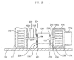
- Fig. 13 is a cross sectional view taken along line C-C of Fig. 12
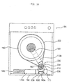
- Fig. 14 is a front view of the drying machine according to the present invention showing that a motor and motor fixing brackets are disposed in the drying machine.
- the drying machine As shown in Figs. 12 to 14, the drying machine according to the present invention comprises a base 152, and a casing 54 placed on the base 152.
- the casing 152 has a clothes inlet 154a, which also acts as a clothes outlet, formed in the front central part of the casing 152, and a door 154b pivotably attached to the casing 154.
- a drum 160 In the casing 10 is rotatably placed a drum 160.
- the drying machine further includes a condenser 166 for condensing moisture laden in the air having passed through the drum 160 by heat exchange between the air having passed through the drum 160 and outside air, a first fan 170 with a circulation duct for blowing the air passing through the condenser 166 into the drum, a second fan 174 with a suction duct for blowing outside air to the condenser 166, a heater 180 for heating the air entering the drum 160 after passing through the condenser 66, a motor 190 for rotating the drum 160 and the first and second fans 170 and 174, supporting members 222 and 224 placed on the base 152, and motor fixing brackets 230 and 232.
- a condenser 166 for condensing moisture laden in the air having passed through the drum 160 by heat exchange between the air having passed through the drum 160 and outside air
- a first fan 170 with a circulation duct for blowing the air passing through the condenser 166 into the drum
- the motor fixing brackets 230 and 232 each have an insert part 234, through which the motor 190 is inserted, and first and second supporting legs 236 and 238 extending downwardly from the opposite sides of the insert part 234, respectively.
- the first and second supporting legs 236 and 238 are fitted on the supporting members 222 and 224.
- the drum 160 has a space large enough to receive a large amount of clothes to be dried therein, and is provided at the inner circumference thereof with vanes 161 for lifting the clothes.
- the condenser 166 has a first passageway 167, through which the circulating air passes, formed in the direction coaxial to the drum 60, and a second passageway 168, through which the outside air passes, formed in the direction perpendicular to the first passageway 167.
- first passageway 167 through which the circulating air passes, formed in the direction coaxial to the drum 60
- second passageway 168 through which the outside air passes, formed in the direction perpendicular to the first passageway 167.
- the first fan 170 is disposed in the first fan housing 171 surrounding the first fan 170.
- the circulation duct comprises a first circulation duct (not shown) extended from the upper part of the drum 160 to the front part of the first passageway 167 of the condenser 166 for guiding the air of high humidity passing through the drum 160 to the first passageway 167 of the condenser 166, a second circulation duct 173a extended from the rear part of the first passageway 167 of the condenser 166 to the first fan housing 171 for guiding the air of low humidity passing through the first passageway 167 of the condenser 166 to the first fan housing 171, and a third circulation duct 173b for guiding the air leaving the first fan housing 171 to the rear of the drum 160.
- a first circulation duct (not shown) extended from the upper part of the drum 160 to the front part of the first passageway 167 of the condenser 166 for guiding the air of high humidity passing through the drum 160 to the first passageway 167 of the condenser 166
- a second circulation duct 173a extended from the rear part of
- the second fan 174 is disposed in the second fan housing 175 surrounding the second fan 174.
- the suction duct comprises a first suction duct 177a connected to the second fan housing 175 for guiding the outside air into the second fan housing 175, a second suction duct 177b extended from one side of the second fan housing 175 to the inlet of the second passageway 168 of the condenser 166 for guiding the air blown by the second fan 174 to the second passageway 168 of the condenser 166, and a third suction duct (not shown) connected to the second passageway 168 of the condenser 166 for guiding the air passing through the second passageway 168 of the condenser 166 to the outside of the drying machine.
- the motor 190 is provided at the front and rear ends thereof with front and rear shafts 190a and 190b, respectively.
- the second fan 174 is attached to the front end of the front shaft 190a, while the first fan 170 is attached to the rear end of the rear shaft 190b.
- a belt 200 is provided around the rear shaft 190b at the center thereof. The belt 200 is also provided around the drum 160.
- vibration isolating rings 210 and 212 for absorbing vibration, respectively.
- the vibration isolating rings 210 and 212 are fitted on the outer circumferences of the hubs 193 and 194.
- the motor fixing brackets 230 and 232 is placed in such a manner that the insert parts 234 are fitted on the outer circumferences of the vibration isolating rings 210 and 212.
- Each of the supporting members 222 and 224 is formed in such a manner that the width between the opposite sides of each of the supporting members 222 and 224 is increased upwardly, while the motor fixing brackets 230 and 232 are formed in such a manner that the distance between the first and second supporting legs 236 and 238 is decreased downwardly.
- the supporting members 222 and 224 and the motor fixing brackets 230 and 232 according to this embodiment are very similar to those of the previous embodiment, the structures of which will not be described.
- Clothes to be dried are put into the drum 160, and the door 154b is closed to operate the drying machine.
- the motor 190 is driven while being supported securely by the motor fixing brackets 230 and 232 and the supporting members 22 and 224.
- the belt 200 running around the rear shafts 190b rotates the drum 160.
- the second fan 174 attached to the front end of the front shaft 190a is rotated at the front of the motor 190 for sucking in outside air.
- the first fan 190b attached to the rear end of the rear shaft 190b is rotated at the rear of the motor 190 for circulating the air between the drum 160 and the condenser 166.
- the clothes to be dried in the drum 160 are lifted by the vanes 161 and then dropped from the vanes 161.
- the air in the casing 154 which has been introduced from the outside, passes through the second passageway 168 of the condenser 166, and then flows out of the casing 154.
- the air in the drum 160 passes through the first passageway 167 of the condenser 166, moisture laden in the air is condensed to reduce the humidity of the air.
- the air of low humidity is heated at a high temperature by the heater 180.
- the heated air is introduced into the drum 160 to dry the clothes, and then circulated through the drum 160, the condenser 166, and the heater 180 to continue drying the clothes.
- the present invention provides a drying machine including supporting members placed on a base, and motor fixing brackets each comprising an insert part, into which a motor is inserted, and first and second supporting legs extended downwardly from the opposite sides of the insert part and fitted on supporting members from the above, respectively, whereby any vibration of the motor is prevented and attachment/detachment of the motor is easy and convenient.
- Each of the supporting members is formed in such a manner that the width between the opposite sides of each of the supporting members is increased upwardly, while the motor fixing brackets are formed in such a manner that the distance between the first and second supporting legs is decreased downwardly, so that the motor fixing brackets are fitted by force on the supporting members, whereby attachment/detachment of the motor fixing brackets is easy and any accidental detachment of the motor fixing brackets from the surrounding members is prevented.
- the supporting members each have a fixing hole penetrating the supporting member from one side of the supporting member to the other side of the supporting member, and the motor fixing brackets are provided at the first and second supporting legs thereof with fixing holes each communicating with the fixing hole of the supporting member, respectively, so that the motor fixing brackets are attached fixedly to the supporting members by means of fixing screws, which are inserted into the fixing holes, at one side of at least one of the first and second supporting legs, whereby repair/replacement of the motor is easy and convenient.
- the motor fixing brackets are configured in such a manner that the distance between the first and second supporting legs at the lower ends of the supporting legs is less than that between the first and second supporting legs at the upper ends of the supporting legs, and the motor fixing brackets are formed of plastic with a prescribed elasticity so that the motor fixing brackets are fitted on the supporting members along the sloping sides of the supporting members, whereby attachment of the motor fixing brackets is easy and convenient.
- the motor fixing brackets each have a horizontal reinforcing bar formed between the opposite sides of the first and second supporting legs thereof, whereby any breakage of the first and second supporting legs is prevented.
- each of the motor fixing brackets are provided at the lower ends thereof with bent parts, respectively, whereby the motor fixing brackets do not shake, the motor fixing brackets can stably support the motor, and the vibration from the motor is not transmitted to the base or the casing.
- the fixing holes of the first and second supporting legs of the motor fixing brackets each have a thread part formed therein only at one side thereof, and the fixing screw has a thread part formed on the outer circumference thereof. Consequently, the first and second supporting legs approach each other by virtue of the engagement of the fixing screw into one of the fixing holes so that the first and second supporting legs come into secure contact with the inclined sides of the supporting members.
- the vibration isolating rings are disposed between the hubs provided at the front and rear parts of the motor and the insert parts of the motor fixing brackets, respectively, whereby the vibration from the motor is absorbed.
Landscapes
- Engineering & Computer Science (AREA)
- Textile Engineering (AREA)
- Detail Structures Of Washing Machines And Dryers (AREA)
- Drying Of Solid Materials (AREA)
- Motor Or Generator Frames (AREA)
Applications Claiming Priority (2)
| Application Number | Priority Date | Filing Date | Title |
|---|---|---|---|
| KR2003002654 | 2003-01-15 | ||
| KR10-2003-0002654A KR100465729B1 (ko) | 2003-01-15 | 2003-01-15 | 건조기 |
Publications (2)
| Publication Number | Publication Date |
|---|---|
| EP1439257A2 true EP1439257A2 (fr) | 2004-07-21 |
| EP1439257A3 EP1439257A3 (fr) | 2006-02-08 |
Family
ID=32588955
Family Applications (1)
| Application Number | Title | Priority Date | Filing Date |
|---|---|---|---|
| EP03006011A Withdrawn EP1439257A3 (fr) | 2003-01-15 | 2003-03-18 | Machine à sécher avec consoles de fixation d'un moteur sur la base de la machine |
Country Status (4)
| Country | Link |
|---|---|
| US (1) | US6874248B2 (fr) |
| EP (1) | EP1439257A3 (fr) |
| KR (1) | KR100465729B1 (fr) |
| CN (1) | CN1258024C (fr) |
Cited By (3)
| Publication number | Priority date | Publication date | Assignee | Title |
|---|---|---|---|---|
| EP1666658A1 (fr) * | 2004-12-01 | 2006-06-07 | Samsung Electronics Co., Ltd. | Sèche-linge avec structure de connexion entre boîtier d'un ventilateur et support d'un moteur |
| WO2019192884A1 (fr) * | 2018-04-02 | 2019-10-10 | Arcelik Anonim Sirketi | Sèche-linge présentant des niveaux sonores réduits |
| EP4119722A3 (fr) * | 2021-07-15 | 2023-02-08 | Miele & Cie. KG | Séchoir à linge |
Families Citing this family (34)
| Publication number | Priority date | Publication date | Assignee | Title |
|---|---|---|---|---|
| KR20040023999A (ko) * | 2002-09-12 | 2004-03-20 | 엘지전자 주식회사 | 의류건조기의 모터축 구조 |
| US7627960B2 (en) * | 2003-06-30 | 2009-12-08 | General Electric Company | Clothes dryer drum projections |
| KR100487759B1 (ko) * | 2003-08-13 | 2005-05-06 | 엘지전자 주식회사 | 의류건조기의 냉각공기 흡입구조 |
| US7093377B2 (en) * | 2003-12-19 | 2006-08-22 | Lg Electronics Inc. | Laundry dryer and an air inlet structure thereof |
| KR101093988B1 (ko) * | 2004-06-05 | 2011-12-15 | 엘지전자 주식회사 | 건조기의 도어 린트 필터 밀착 장치 |
| EP1637643A3 (fr) * | 2004-09-06 | 2009-01-07 | Samsung Electronics Co., Ltd. | Sèche-linge |
| DE102004055942A1 (de) * | 2004-11-19 | 2006-05-24 | BSH Bosch und Siemens Hausgeräte GmbH | Wäschetrockner |
| WO2006062262A1 (fr) * | 2004-12-06 | 2006-06-15 | Lg Electronics Inc. | Seche-linge |
| EP1783266B1 (fr) * | 2005-11-03 | 2017-04-19 | Electrolux Home Products Corporation N.V. | Sèche-linge |
| KR100710395B1 (ko) * | 2006-01-25 | 2007-04-24 | 엘지전자 주식회사 | 의류 건조기 |
| EP1876280B1 (fr) * | 2006-07-06 | 2010-09-22 | Candy S.p.A. | Tambour pour lave-linge, sèche-linge et similaires |
| CN101113563B (zh) * | 2006-07-28 | 2011-02-16 | 南京乐金熊猫电器有限公司 | 衣物烘干机及衣物烘干机的操作方法 |
| DE102007046068B4 (de) * | 2006-10-02 | 2018-06-28 | Lg Electronics Inc. | Vorrichtung zum Erkennen einer Riementrennung bei einem Trockner sowie Verfahren zum Erkennen dieses Vorgangs |
| KR101256145B1 (ko) * | 2007-11-05 | 2013-04-23 | 동부대우전자 주식회사 | 히터 내장형 흡기관을 구비하는 건조기 |
| KR101308510B1 (ko) * | 2007-11-05 | 2013-09-12 | 동부대우전자 주식회사 | 히터 내장형 흡기관을 구비하는 건조기 |
| EP2063014B1 (fr) * | 2007-11-21 | 2013-09-18 | LG Electronics Inc. | Machine à laver |
| EP2063013B1 (fr) * | 2007-11-21 | 2013-09-18 | LG Electronics Inc. | Machine à laver |
| KR101435811B1 (ko) * | 2007-11-21 | 2014-08-29 | 엘지전자 주식회사 | 의류처리장치 |
| KR101467752B1 (ko) * | 2007-11-21 | 2014-12-03 | 엘지전자 주식회사 | 의류처리장치 |
| KR20090052458A (ko) * | 2007-11-21 | 2009-05-26 | 엘지전자 주식회사 | 의류처리장치 |
| EP2063012B1 (fr) | 2007-11-21 | 2013-09-18 | LG Electronics Inc. | Machine à laver |
| CA2627713A1 (fr) * | 2008-03-28 | 2009-09-28 | Mabe Canada Inc. | Support de moteur de secheuse |
| ITMC20090003A1 (it) * | 2009-01-14 | 2010-07-15 | Meccanica Generale Srl | Vasca per macchina lavatrice o lavasciugatrice. |
| US8424834B2 (en) * | 2009-06-24 | 2013-04-23 | Magna International | Composite appliance base |
| US8235351B1 (en) * | 2009-08-27 | 2012-08-07 | Lockheed Martin Corporation | Shock load isolation mounting |
| US9758919B2 (en) | 2010-08-09 | 2017-09-12 | Lg Electronics Inc. | Apparatus for treating laundry |
| US9096965B2 (en) | 2010-08-09 | 2015-08-04 | Lg Electronics Inc. | Apparatus for treating laundry having a ring shaped circular guide |
| US20130239428A1 (en) * | 2012-03-14 | 2013-09-19 | Alliance Laundry Systems Llc | Method to reverse cylinder drive in a direct belt on basket dryer/tumbler |
| CN104709119B (zh) * | 2015-01-28 | 2017-08-08 | 宁波双林汽车部件股份有限公司 | 一种汽车电动座椅电机的便捷安装装置 |
| WO2016144757A1 (fr) * | 2015-03-06 | 2016-09-15 | Hg LAUNDRY SYSTEMS, LLC | Combinaison lave-linge/sèche-linge |
| CN105970544B (zh) * | 2016-05-31 | 2019-01-18 | 无锡小天鹅股份有限公司 | 衣物处理装置的热泵模组及衣物处理装置 |
| US20160332511A1 (en) * | 2016-07-25 | 2016-11-17 | Caterpillar Inc. | Mounting assembly |
| KR102736197B1 (ko) * | 2019-07-02 | 2024-11-28 | 엘지전자 주식회사 | 식기세척기 |
| EP4603629A1 (fr) * | 2020-03-05 | 2025-08-20 | LG Electronics Inc. | Appareil de traitement du linge de type à empilement |
Family Cites Families (16)
| Publication number | Priority date | Publication date | Assignee | Title |
|---|---|---|---|---|
| GB691284A (en) * | 1950-07-15 | 1953-05-06 | Arne Sven Birger Bergman | Motor mounting device |
| US2982504A (en) * | 1956-10-18 | 1961-05-02 | Gen Electric | Machine mounting assembly |
| US3066898A (en) * | 1961-08-31 | 1962-12-04 | Leonard T Haynes | Electric motor and engine mount |
| IT940760B (it) * | 1970-12-04 | 1973-02-20 | Klein Schanzlin & Becker Ag | Disposizione di fissaggio di pompe centrifughe su piastre di base |
| US3891345A (en) * | 1973-11-23 | 1975-06-24 | Worthington Pump Int | Supporting foot means for a separately coupled centrifugal pump |
| US3983429A (en) * | 1975-05-08 | 1976-09-28 | Westinghouse Electric Corporation | Adjustable motor base |
| DE7515298U (de) * | 1975-05-13 | 1975-10-02 | Licentia Gmbh | Wäschetrockner |
| US4097012A (en) * | 1976-08-05 | 1978-06-27 | Wadsworth Equipment Company | Mounting bracket assembly |
| DE8011829U1 (de) * | 1980-04-30 | 1981-11-05 | G. Bauknecht Gmbh, 7000 Stuttgart | Wäschetrockner |
| US4621438A (en) * | 1980-12-04 | 1986-11-11 | Donald M. Thompson | Energy efficient clothes dryer |
| US4805859A (en) * | 1987-11-05 | 1989-02-21 | Don Hudson | Apparatus for securing containers to moving platforms |
| IT215681Z2 (it) * | 1988-02-04 | 1990-10-22 | Zanussi A Spa Industrie | Dispositivo di supporto e di fissaggio del motore di azionamento di una lavabiancheria a cesto. |
| US5501021A (en) * | 1995-05-30 | 1996-03-26 | White Consolidated Industries, Inc. | Common idler strap for use in a clothes dryer |
| US5699992A (en) * | 1996-01-29 | 1997-12-23 | Knf Neuberger Gmbh | Pump stand |
| JPH11191941A (ja) * | 1997-10-22 | 1999-07-13 | Hoshizaki Electric Co Ltd | ファンモーターの取付構造及びそのブラケットの製造方法 |
| US6378834B1 (en) * | 2000-02-09 | 2002-04-30 | Emerson Electric Co. | Shaft supporting hub ring with integral self-locking mechanism |
-
2003
- 2003-01-15 KR KR10-2003-0002654A patent/KR100465729B1/ko not_active Expired - Fee Related
- 2003-03-13 US US10/386,516 patent/US6874248B2/en not_active Expired - Lifetime
- 2003-03-18 EP EP03006011A patent/EP1439257A3/fr not_active Withdrawn
- 2003-04-16 CN CNB031101968A patent/CN1258024C/zh not_active Expired - Fee Related
Cited By (3)
| Publication number | Priority date | Publication date | Assignee | Title |
|---|---|---|---|---|
| EP1666658A1 (fr) * | 2004-12-01 | 2006-06-07 | Samsung Electronics Co., Ltd. | Sèche-linge avec structure de connexion entre boîtier d'un ventilateur et support d'un moteur |
| WO2019192884A1 (fr) * | 2018-04-02 | 2019-10-10 | Arcelik Anonim Sirketi | Sèche-linge présentant des niveaux sonores réduits |
| EP4119722A3 (fr) * | 2021-07-15 | 2023-02-08 | Miele & Cie. KG | Séchoir à linge |
Also Published As
| Publication number | Publication date |
|---|---|
| CN1258024C (zh) | 2006-05-31 |
| KR20040065604A (ko) | 2004-07-23 |
| CN1517481A (zh) | 2004-08-04 |
| KR100465729B1 (ko) | 2005-01-13 |
| US20040134092A1 (en) | 2004-07-15 |
| EP1439257A3 (fr) | 2006-02-08 |
| US6874248B2 (en) | 2005-04-05 |
Similar Documents
| Publication | Publication Date | Title |
|---|---|---|
| EP1439257A2 (fr) | Machine à sécher avec consoles de fixation d'un moteur sur la base de la machine | |
| CN102634966B (zh) | 衣物处理机 | |
| KR20140065265A (ko) | 히트펌프를 구비한 건조기 | |
| KR20040046459A (ko) | 응축식 의류 건조기용 응축기의 냉각 유로 | |
| US7562467B2 (en) | Dryer, and motor mounting structure of the same | |
| US7069669B2 (en) | Clothes dryer | |
| JP4490251B2 (ja) | 乾燥機兼用洗濯機 | |
| KR100465721B1 (ko) | 건조기의 프론트 서포터 마운팅 구조 | |
| US7093378B2 (en) | Motor supporting apparatus of clothing drier | |
| EP1584732B1 (fr) | Sèche-linge | |
| KR100480926B1 (ko) | 의류건조기의 응축기 | |
| US7043944B2 (en) | Drum type washing and drying apparatus | |
| KR101059814B1 (ko) | 의류건조기 | |
| US20070089316A1 (en) | Clothing drying machine | |
| KR20190000515A (ko) | 의류 건조기 | |
| EP4389953B1 (fr) | Lave-linge avec fonction de séchage | |
| US20050252032A1 (en) | Clothes dryer | |
| US7350319B2 (en) | Clothing dryer | |
| CA2506502C (fr) | Secheuse a lessive a nouvelle structure d'installation du tuyau d'echappement | |
| KR101137319B1 (ko) | 응축식 의류건조기의 리버서블 도어 구조 | |
| EP1905882B1 (fr) | Sèche-linge | |
| KR100452366B1 (ko) | 건조기의 필터 커버 조립 구조 | |
| US20050229648A1 (en) | Drum type washer and dryer | |
| KR101034196B1 (ko) | 의류건조기 | |
| KR20050057808A (ko) | 건조기의 드럼장치 |
Legal Events
| Date | Code | Title | Description |
|---|---|---|---|
| PUAI | Public reference made under article 153(3) epc to a published international application that has entered the european phase |
Free format text: ORIGINAL CODE: 0009012 |
|
| AK | Designated contracting states |
Kind code of ref document: A2 Designated state(s): AT BE BG CH CY CZ DE DK EE ES FI FR GB GR HU IE IT LI LU MC NL PT RO SE SI SK TR |
|
| AX | Request for extension of the european patent |
Extension state: AL LT LV MK |
|
| PUAL | Search report despatched |
Free format text: ORIGINAL CODE: 0009013 |
|
| AK | Designated contracting states |
Kind code of ref document: A3 Designated state(s): AT BE BG CH CY CZ DE DK EE ES FI FR GB GR HU IE IT LI LU MC NL PT RO SE SI SK TR |
|
| AX | Request for extension of the european patent |
Extension state: AL LT LV MK |
|
| 17P | Request for examination filed |
Effective date: 20060801 |
|
| AKX | Designation fees paid |
Designated state(s): DE FR GB |
|
| 17Q | First examination report despatched |
Effective date: 20080729 |
|
| STAA | Information on the status of an ep patent application or granted ep patent |
Free format text: STATUS: THE APPLICATION IS DEEMED TO BE WITHDRAWN |
|
| 18D | Application deemed to be withdrawn |
Effective date: 20111005 |