EP1439350A2 - Trägeranordnung für eine Gasturbinenbrennkammer - Google Patents
Trägeranordnung für eine Gasturbinenbrennkammer Download PDFInfo
- Publication number
- EP1439350A2 EP1439350A2 EP03257117A EP03257117A EP1439350A2 EP 1439350 A2 EP1439350 A2 EP 1439350A2 EP 03257117 A EP03257117 A EP 03257117A EP 03257117 A EP03257117 A EP 03257117A EP 1439350 A2 EP1439350 A2 EP 1439350A2
- Authority
- EP
- European Patent Office
- Prior art keywords
- support
- aft
- support assembly
- combustor
- gas turbine
- Prior art date
- Legal status (The legal status is an assumption and is not a legal conclusion. Google has not performed a legal analysis and makes no representation as to the accuracy of the status listed.)
- Withdrawn
Links
- 239000011153 ceramic matrix composite Substances 0.000 description 16
- 239000007789 gas Substances 0.000 description 12
- 239000000463 material Substances 0.000 description 10
- 238000000034 method Methods 0.000 description 7
- 239000002184 metal Substances 0.000 description 6
- 229910052751 metal Inorganic materials 0.000 description 6
- 239000000446 fuel Substances 0.000 description 5
- PXHVJJICTQNCMI-UHFFFAOYSA-N Nickel Chemical compound [Ni] PXHVJJICTQNCMI-UHFFFAOYSA-N 0.000 description 4
- HBMJWWWQQXIZIP-UHFFFAOYSA-N silicon carbide Chemical compound [Si+]#[C-] HBMJWWWQQXIZIP-UHFFFAOYSA-N 0.000 description 4
- 238000002485 combustion reaction Methods 0.000 description 3
- 238000001816 cooling Methods 0.000 description 3
- 229910010271 silicon carbide Inorganic materials 0.000 description 3
- VYPSYNLAJGMNEJ-UHFFFAOYSA-N Silicium dioxide Chemical compound O=[Si]=O VYPSYNLAJGMNEJ-UHFFFAOYSA-N 0.000 description 2
- PNEYBMLMFCGWSK-UHFFFAOYSA-N aluminium oxide Inorganic materials [O-2].[O-2].[O-2].[Al+3].[Al+3] PNEYBMLMFCGWSK-UHFFFAOYSA-N 0.000 description 2
- 239000000919 ceramic Substances 0.000 description 2
- 239000000835 fiber Substances 0.000 description 2
- 239000011159 matrix material Substances 0.000 description 2
- 229910052759 nickel Inorganic materials 0.000 description 2
- 229910000601 superalloy Inorganic materials 0.000 description 2
- 238000011144 upstream manufacturing Methods 0.000 description 2
- OKTJSMMVPCPJKN-UHFFFAOYSA-N Carbon Chemical compound [C] OKTJSMMVPCPJKN-UHFFFAOYSA-N 0.000 description 1
- XUIMIQQOPSSXEZ-UHFFFAOYSA-N Silicon Chemical compound [Si] XUIMIQQOPSSXEZ-UHFFFAOYSA-N 0.000 description 1
- -1 Textron's SCS-6) Chemical compound 0.000 description 1
- 230000006978 adaptation Effects 0.000 description 1
- INJRKJPEYSAMPD-UHFFFAOYSA-N aluminum;silicic acid;hydrate Chemical compound O.[Al].[Al].O[Si](O)(O)O INJRKJPEYSAMPD-UHFFFAOYSA-N 0.000 description 1
- 230000000712 assembly Effects 0.000 description 1
- 238000000429 assembly Methods 0.000 description 1
- 230000004323 axial length Effects 0.000 description 1
- 229910052799 carbon Inorganic materials 0.000 description 1
- 239000000567 combustion gas Substances 0.000 description 1
- 239000002131 composite material Substances 0.000 description 1
- 238000013016 damping Methods 0.000 description 1
- GUJOJGAPFQRJSV-UHFFFAOYSA-N dialuminum;dioxosilane;oxygen(2-);hydrate Chemical compound O.[O-2].[O-2].[O-2].[Al+3].[Al+3].O=[Si]=O.O=[Si]=O.O=[Si]=O.O=[Si]=O GUJOJGAPFQRJSV-UHFFFAOYSA-N 0.000 description 1
- 239000011256 inorganic filler Substances 0.000 description 1
- 229910003475 inorganic filler Inorganic materials 0.000 description 1
- 239000010443 kyanite Substances 0.000 description 1
- 229910052850 kyanite Inorganic materials 0.000 description 1
- 230000013011 mating Effects 0.000 description 1
- 239000007769 metal material Substances 0.000 description 1
- 150000002739 metals Chemical class 0.000 description 1
- 239000010445 mica Substances 0.000 description 1
- 229910052618 mica group Inorganic materials 0.000 description 1
- 238000012986 modification Methods 0.000 description 1
- 230000004048 modification Effects 0.000 description 1
- 229910052901 montmorillonite Inorganic materials 0.000 description 1
- 230000003647 oxidation Effects 0.000 description 1
- 238000007254 oxidation reaction Methods 0.000 description 1
- 239000002245 particle Substances 0.000 description 1
- 229910052903 pyrophyllite Inorganic materials 0.000 description 1
- 239000012783 reinforcing fiber Substances 0.000 description 1
- 230000000717 retained effect Effects 0.000 description 1
- 229910052594 sapphire Inorganic materials 0.000 description 1
- 239000010980 sapphire Substances 0.000 description 1
- 230000035939 shock Effects 0.000 description 1
- 238000004904 shortening Methods 0.000 description 1
- 150000004760 silicates Chemical class 0.000 description 1
- 229910052710 silicon Inorganic materials 0.000 description 1
- 239000010703 silicon Substances 0.000 description 1
- 239000000377 silicon dioxide Substances 0.000 description 1
- 229910052814 silicon oxide Inorganic materials 0.000 description 1
- 238000006467 substitution reaction Methods 0.000 description 1
- 239000000454 talc Substances 0.000 description 1
- 229910052623 talc Inorganic materials 0.000 description 1
- 239000010456 wollastonite Substances 0.000 description 1
- 229910052882 wollastonite Inorganic materials 0.000 description 1
Images


Classifications
-
- F—MECHANICAL ENGINEERING; LIGHTING; HEATING; WEAPONS; BLASTING
- F23—COMBUSTION APPARATUS; COMBUSTION PROCESSES
- F23R—GENERATING COMBUSTION PRODUCTS OF HIGH PRESSURE OR HIGH VELOCITY, e.g. GAS-TURBINE COMBUSTION CHAMBERS
- F23R3/00—Continuous combustion chambers using liquid or gaseous fuel
- F23R3/007—Continuous combustion chambers using liquid or gaseous fuel constructed mainly of ceramic components
-
- F—MECHANICAL ENGINEERING; LIGHTING; HEATING; WEAPONS; BLASTING
- F23—COMBUSTION APPARATUS; COMBUSTION PROCESSES
- F23R—GENERATING COMBUSTION PRODUCTS OF HIGH PRESSURE OR HIGH VELOCITY, e.g. GAS-TURBINE COMBUSTION CHAMBERS
- F23R3/00—Continuous combustion chambers using liquid or gaseous fuel
- F23R3/42—Continuous combustion chambers using liquid or gaseous fuel characterised by the arrangement or form of the flame tubes or combustion chambers
- F23R3/50—Combustion chambers comprising an annular flame tube within an annular casing
-
- F—MECHANICAL ENGINEERING; LIGHTING; HEATING; WEAPONS; BLASTING
- F23—COMBUSTION APPARATUS; COMBUSTION PROCESSES
- F23R—GENERATING COMBUSTION PRODUCTS OF HIGH PRESSURE OR HIGH VELOCITY, e.g. GAS-TURBINE COMBUSTION CHAMBERS
- F23R3/00—Continuous combustion chambers using liquid or gaseous fuel
- F23R3/42—Continuous combustion chambers using liquid or gaseous fuel characterised by the arrangement or form of the flame tubes or combustion chambers
- F23R3/60—Support structures; Attaching or mounting means
-
- F—MECHANICAL ENGINEERING; LIGHTING; HEATING; WEAPONS; BLASTING
- F05—INDEXING SCHEMES RELATING TO ENGINES OR PUMPS IN VARIOUS SUBCLASSES OF CLASSES F01-F04
- F05B—INDEXING SCHEME RELATING TO WIND, SPRING, WEIGHT, INERTIA OR LIKE MOTORS, TO MACHINES OR ENGINES FOR LIQUIDS COVERED BY SUBCLASSES F03B, F03D AND F03G
- F05B2230/00—Manufacture
- F05B2230/60—Assembly methods
- F05B2230/604—Assembly methods using positioning or alignment devices for aligning or centering, e.g. pins
- F05B2230/606—Assembly methods using positioning or alignment devices for aligning or centering, e.g. pins using maintaining alignment while permitting differential dilatation
-
- F—MECHANICAL ENGINEERING; LIGHTING; HEATING; WEAPONS; BLASTING
- F23—COMBUSTION APPARATUS; COMBUSTION PROCESSES
- F23R—GENERATING COMBUSTION PRODUCTS OF HIGH PRESSURE OR HIGH VELOCITY, e.g. GAS-TURBINE COMBUSTION CHAMBERS
- F23R2900/00—Special features of, or arrangements for continuous combustion chambers; Combustion processes therefor
- F23R2900/00014—Reducing thermo-acoustic vibrations by passive means, e.g. by Helmholtz resonators
Definitions
- the present invention relates generally to the use of Ceramic Matrix Composite liners in a gas turbine engine combustor and, in particular, to the damping of vibrations experienced by the combustor.
- U.S. Patent 6,397,603 to Edmondson et al. also discloses a combustor having a liner made of Ceramic Matrix Composite materials, where the liner is mated with an intermediate liner dome support member in order to accommodate differential thermal expansion without undue stress on the liner.
- the Edmondson et al. patent further includes the ability to regulate part of the cooling air flow through the interface joint.
- CMC liners Another concern with the implementation of CMC liners is reducing the amount of vibration experienced by such combustor. It has been learned that replacing traditional metal liners with CMC liners causes the vibration response of the combustor to drop into the operating range of the engine. This appears to stem from the radially free manner of mounting the liners at a forward end, as described in a patent application entitled "Mounting Assembly For The Forward End Of A Ceramic Matrix Composite Liner In A Gas Turbine Engine Combustor," having U.S. Serial No.
- a support member to be developed for use with a combustor having a CMC liner, where such support member is able to stiffen the combustor and increase the frequency out of the operating range of the engine. It is also desirable for the support member to have a geometry which minimizes blockage of air flow.
- a support assembly for a gas turbine engine combustor including an inner liner and an inner casing spaced therefrom, wherein a longitudinal centerline axis extends through the gas turbine engine.
- the support assembly includes an annular inner support cone located adjacent an aft end of said inner liner, an annular nozzle support connected to the inner support cone, and a plurality of support members connected at a first end to a forward end of the inner liner and connected at a second end to the inner support cone.
- a combustor for a gas turbine engine having a longitudinal centerline axis extending therethrough including: an inner liner having a forward end and an aft end, where the inner liner is made of a ceramic matrix composite material; an inner casing spaced from the inner liner so as to form an inner passage therebetween; an annular inner support cone located adjacent to the inner liner aft end, where the inner support cone is made of a metal; and, a plurality of circumferentially spaced support members connected at a first end to the inner liner forward end and connected at a second end to the annular inner support cone.
- the support members provide additional stiffness to the combustor and cause the vibrations experienced by the combustor to be outside the operating frequency of the gas turbine engine.
- a method of providing additional stiffness to a gas turbine engine combustor wherein an inner liner of the combustor is connected at a forward end and at an aft end in a manner permitting radial movement.
- the method includes the steps of movably connecting a plurality of support members at a forward portion to a forward end of the inner liner and fixedly connecting the support members at an aft portion to an annular inner support cone. Additional steps of the method may include fixedly connecting the support members at a forward portion to a dome and/or an inner cowl of the combustor.
- FIG. 1 depicts an exemplary gas turbine engine combustor 10 which conventionally generates combustion gases that are discharged therefrom and channeled to one or more pressure turbines. Such turbine(s) drive one or more pressure compressors upstream of combustor 10 through suitable shaft(s). A longitudinal or axial centerline axis 12 is provided through the gas turbine engine for reference purposes.
- combustor 10 further includes a combustion chamber 14 defined by an outer liner 16, an inner liner 18 and a dome 20.
- Combustor dome 20 is shown as being single annular in design so that a single circumferential row of fuel/air mixers 22 are provided within openings formed in such dome 20, although a multiple annular dome may be utilized.
- a fuel nozzle (not shown) provides fuel to fuel/air mixers 22 in accordance with desired performance of combustor 10 at various engine operating states.
- an outer annular cowl 24 and an inner annular cowl 26 are located upstream of combustion chamber 14 so as to direct air flow into fuel/air mixers 22, as well as an outer passage 28 between outer liner 16 and an outer casing 30 and an inner passage 32 between inner liner 18 and an inner casing 31.
- An inner annular support member 34 also known herein as an inner support cone, is further shown as being connected to a nozzle support 33 by means of a plurality of bolts 37 and nuts 39. In this way, convective cooling air is provided to the outer surfaces of outer and inner liners 16 and 18 and air for film cooling is provided to the inner surfaces of such liners.
- a diffuser 35 receives the air flow from the compressor(s) and provides it to combustor 10.
- outer and inner liners 16 and 18 are preferably made of a ceramic matrix composite (CMC), which is a non-metallic material having high temperature capability and low ductility.
- CMC ceramic matrix composite
- Exemplary composite materials utilized for such liners include silicon carbide, silicon, silica or alumina matrix materials and combinations thereof.
- ceramic fibers are embedded within the matrix such as oxidation stable reinforcing fibers including monofilaments like sapphire and silicon carbide (e.g., Textron's SCS-6), as well as rovings and yarn including silicon carbide (e.g., Nippon Carbon's NICALON®, Ube Industries' TYRANNO®, and Dow Corning's SYLRAMIC®), alumina silicates (e.g., Nextel's 440 and 480), and chopped whiskers and fibers (e.g., Nextel's 440 and SAFFIL®), and optionally ceramic particles (e.g., oxides of Si, Al, Zr, Y and combinations thereof) and inorganic fillers (e.g., pyrophyllite, wollastonite, mica, talc, kyanite and montmorillonite).
- CMC materials typically have coefficients of thermal expansion in the range of about 1.3 x 10 -6 in/in/°F to about 3.5
- inner casing 31, nozzle support 33, and inner support cone 34 are typically made of a metal, such as a nickel-based superalloy (having a coefficient of thermal expansion of about 8.3-8.6 x 10 -6 in/in/°F in a temperature range of approximately 1000-1200°F).
- a nickel-based superalloy having a coefficient of thermal expansion of about 8.3-8.6 x 10 -6 in/in/°F in a temperature range of approximately 1000-1200°F.
- a mounting assembly 38 is provided for a forward end 40 of inner liner 18, an aft portion 42 of inner cowl 26, and an inner portion 44 of dome 20 so as to accommodate differences in thermal growth experienced by such components. More specifically, it will be understood that inner liner forward end 40, inner cowl aft portion 42 and dome inner portion 44 each include a plurality of circumferentially spaced openings 46, 48 and 50, respectively, which are positioned so as to be in alignment.
- a pin member 52 preferably extends through each set of aligned openings and includes a head portion 54 at a first end thereof.
- Pin members 52 preferably include threads 56 formed thereon so that a nut 58 is adjustably connected to a second end of each pin member 52 opposite head portion 54.
- each nut 58 preferably includes a flange portion 60 extending from an outer surface 62 thereof.
- a bushing 64 is also preferably located on each pin member 52 and fixed at a position intermediate head portion 54 and nut 58 between head portion 54 and inner cowl aft portion 42. In this way, nuts 58 and head portions 54 fixedly connect together inner cowl aft portion 42, dome inner portion 44 and bushings 64. It will be understood that while inner cowl aft portion 42 is located between dome inner portion 44 and bushings 64, combustor 10 could be configured so that dome inner portion 44 is located between inner cowl aft portion 42 and bushings 64.
- Openings 46 in inner liner forward end 40 are preferably sized, however, so that bushings 64 are able to slide radially therethrough as inner cowl aft portion 42 and dome inner portion 44 experience thermal growth greater than inner liner forward end 40.
- inner cowl aft portion 42 and dome inner portion 44 are able to move between a first radial position and a second radial position.
- a height 66 of bushings 64 should be sized great enough to accommodate the radial thermal growth of inner cowl aft portion 42 and dome inner portion 44.
- pin head portion 54 will have a diameter 68 greater than a diameter 70 of an opening 72 in bushings 64.
- inner cowl aft portion 42 and dome inner portion 44 not be able to move axially or circumferentially with respect to inner liner forward end 40. Accordingly, an annular member 74 having a channel 76 formed therein is provided adjacent dome inner portion 44. A plurality of circumferentially spaced openings 78 are formed in annular member 74 which are aligned with openings 46 in inner liner forward end 40, openings 48 in inner cowl aft portion 42 and openings 50 in dome inner portion 44. Nuts 58 are then positioned so that flange portions 60 thereof are located within channel 76 and fixedly connect bushings 64, inner cowl aft portion 42, dome inner portion 44 and annular member 74.
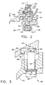
- a mounting assembly 80 is provided for an aft end 82 of inner liner 18 and inner support cone 34 which accommodates varying thermal growth experienced by such components. It will be appreciated that mounting assembly 80 shown in Fig. 3 is prior to any thermal growth experienced by inner liner 18, inner support cone 34 and possibly nozzle support 33. More specifically, it will be understood that inner support cone 34 has a plurality of circumferentially spaced openings 84 formed in a portion 86 thereof and inner liner aft end 82, which has an increased thickness, preferably includes a plurality of circumferentially spaced partial openings or holes 88 formed therein which are positioned so as to be in alignment with openings 84.
- a pin member 90 preferably extends through each opening 84 and is received in a corresponding partial opening 88 in inner liner aft end 82.
- Pin members 90 may each include a head portion at one end thereof.
- openings 84 may include a portion which is either chamfered or otherwise has an enlarged diameter so as to better receive such head portion of pin members 90. Further, the location and/or depth of such portion may also be utilized to verify that pin members 90 are properly positioned within partial openings 88 of inner liner aft end 82.
- a device 94 is utilized to retain pin members 90 in openings 84 and partial openings 88.
- a flexible metal band 96 is preferably inserted within an annular groove portion 97 formed in inner support cone 34 which intersects each opening 84 in inner support cone 34 to provide a mechanical stop.
- band 96 is preferably continuous within annular groove portion 97 and is of sufficient length so as to overlap for at least a portion of the circumference therein.
- Band 96 also preferably has a width 98 which is sized to be retained within annular groove portion 97 of inner support cone 34.
- partial openings 88 in inner liner aft end 82 are preferably sized so that pin members 90, and therefore inner support cone 34 and nozzle support 33, are able to slide radially with respect to inner liner aft end 82 as inner support cone 34 and nozzle support 33 experience thermal growth greater than inner liner 18. Accordingly, inner support cone 34 is able to move between a first radial position and a second radial position.
- Partial openings 88 may be substantially circular (when viewed from a bottom radial perspective) so as to permit only radial movement of pin members 90 and inner support cone 34, but preferably are ovular in shape so that a major axis thereof is aligned substantially parallel to longitudinal centerline axis 12.
- pin members 90, nozzle support 33 and inner support cone 34 are able to slide axially with respect to inner liner aft end 82 when thermal growth of nozzle support 33 and inner support cone 34 are greater than inner liner aft end 82. It will be appreciated then that nozzle support 33 and inner support cone 34 are also able to move between a first axial position and a second axial position. Partial openings 88 will also preferably have a circumferential length along a minor axis which is substantially the same as a diameter for openings 84 so that circumferential movement of inner support cone 34 and support nozzle 33 are discouraged.
- a length 92 of pin members 90, a depth 99 of partial openings 88, and an axial length 100 along the major axis of partial openings 88 will be sized so as to permit a desirable amount of thermal growth for nozzle support 33 and inner support cone 34.
- each pin member 90 may include a partial opening formed therein which includes threads along a sidewall thereof. This is provided so that there will be an easy way of retrieving pin member 90 once device 94 is removed. More specifically, a tool or other device may be threadably mated with such threads of the partial opening so that pin member 90 may be lifted out of opening 84 and partial opening 88.
- a plurality of circumferentially spaced support members 102 are preferably connected at an aft end to inner support cone 34 and extend axially forward to be movably connected at a forward portion with forward end 40 of inner liner 18 via mounting assembly 38.
- each drag link 102 preferably is made of a nickel-based superalloy and has a wishbone-type shape.
- Each drag link 102 further includes a first portion 104 having a forward end 106 and aft end 108, as well as a second portion 110 having a forward end 112 and an aft end 114 which is oriented at a circumferential angle 116 to first portion 104.
- a common junction portion 118 is connected to aft ends 108 and 114 of first and second portions 104 and 110, respectively.
- An aft portion 120 of each drag link 102 extends from common junction portion 118. It will be appreciated that aft portion 120 includes an opening 122 therein so that it may be connected to inner support cone 34 via a bolt 124 and nut 126 (see Fig. 1).
- aft portion 120 of each drag link 102 preferably includes a step portion 144 from common junction portion 118 so that it has a reduced thickness 146.
- first and second drag link portions 104 and 110 each include a forward section 128 and 130, respectively, which preferably are oriented at a radial angle 132 and 134 to longitudinal axes 136 and 138 extending through such first and second portions 104 and 110.
- Forward sections 128 and 130 are preferably substantially parallel to inner liner forward end 40 (i.e., so as to be substantially perpendicular to an axis 53 of pin members 52 of mounting assembly 38) and include openings 140 and 142 therethrough.
- forward section 128 of first drag link portion 104 is positioned between bushing 64 and pin head portion 54.
- first and second drag link portions 104 and 110 are preferably movably connected to inner liner forward end 40 while being fixedly connected to inner cowl aft portion 42 and dome inner portion 44.
- a method of providing additional stiffness to a gas turbine engine combustor is exhibited via drag links 102 described hereinabove.
- This method is particularly useful when the mounting assemblies 38 and 80 for the forward and aft ends 40 and 82, respectively, of inner liner 18 are configured to permit radial movement (e.g., utilized in the case where inner liner 18 is made of a material having a lower coefficient of thermal expansion than inner support cone 34 located adjacent thereto).
- the steps of such method preferably include movably connecting a plurality of drag links 102 at a forward portion to forward end 40 of inner liner 18 and fixedly connecting drag links 102 at an aft portion 120 to inner support cone 34. More particularly, such method may include the steps of fixedly connecting the forward portion of drag links 102 to inner cowl 26 and/or dome 20.
- drag link support member for a combustor having CMC liners
- drag link support member may be altered or modified so as to better accommodate connection with the inner support cone and/or the inner liner.
Landscapes
- Engineering & Computer Science (AREA)
- Chemical & Material Sciences (AREA)
- Combustion & Propulsion (AREA)
- Mechanical Engineering (AREA)
- General Engineering & Computer Science (AREA)
- Ceramic Engineering (AREA)
- Turbine Rotor Nozzle Sealing (AREA)
Applications Claiming Priority (2)
| Application Number | Priority Date | Filing Date | Title |
|---|---|---|---|
| US342040 | 2003-01-14 | ||
| US10/342,040 US6775985B2 (en) | 2003-01-14 | 2003-01-14 | Support assembly for a gas turbine engine combustor |
Publications (2)
| Publication Number | Publication Date |
|---|---|
| EP1439350A2 true EP1439350A2 (de) | 2004-07-21 |
| EP1439350A3 EP1439350A3 (de) | 2006-01-18 |
Family
ID=32594831
Family Applications (1)
| Application Number | Title | Priority Date | Filing Date |
|---|---|---|---|
| EP03257117A Withdrawn EP1439350A3 (de) | 2003-01-14 | 2003-11-12 | Trägeranordnung für eine Gasturbinenbrennkammer |
Country Status (2)
| Country | Link |
|---|---|
| US (1) | US6775985B2 (de) |
| EP (1) | EP1439350A3 (de) |
Cited By (11)
| Publication number | Priority date | Publication date | Assignee | Title |
|---|---|---|---|---|
| GB2415229A (en) * | 2004-06-17 | 2005-12-21 | Snecma Moteurs | Mounting a turbine nozzle on a combustion chamber having CMC walls in a gas turbine |
| JP2009063166A (ja) * | 2007-09-07 | 2009-03-26 | Boeing Co:The | 熱継手 |
| RU2439436C1 (ru) * | 2010-06-07 | 2012-01-10 | Открытое акционерное общество "Авиадвигатель" | Камера сгорания газотурбинного двигателя |
| WO2013106119A3 (en) * | 2011-12-15 | 2013-10-10 | United Technologies Corporation | Mounting apparatus for a trailing edge box of a gas turbine augmentor |
| WO2013163510A1 (en) * | 2012-04-27 | 2013-10-31 | General Electric Company | Connecting gas turbine engine annular members |
| US8726675B2 (en) | 2007-09-07 | 2014-05-20 | The Boeing Company | Scalloped flexure ring |
| EP3211311A1 (de) * | 2016-02-25 | 2017-08-30 | General Electric Company | Brennkammeranordnung |
| EP3211321A1 (de) * | 2016-02-25 | 2017-08-30 | General Electric Company | Brennkammeranordnung |
| EP2481887A3 (de) * | 2011-01-26 | 2017-12-06 | United Technologies Corporation | Zwischenwellendichtung mit Stützverbindung |
| EP3382281A1 (de) * | 2017-03-29 | 2018-10-03 | Delavan, Inc. | Brennkammerwände und aufsätze zum aufsetzen auf düsen |
| FR3119646A1 (fr) * | 2021-02-11 | 2022-08-12 | Safran Aircraft Engines | Rotor de turbomachine |
Families Citing this family (16)
| Publication number | Priority date | Publication date | Assignee | Title |
|---|---|---|---|---|
| FR2840974B1 (fr) * | 2002-06-13 | 2005-12-30 | Snecma Propulsion Solide | Anneau d'etancheite pour cahmbre de combustion et chambre de combustion comportant un tel anneau |
| US7007480B2 (en) * | 2003-04-09 | 2006-03-07 | Honeywell International, Inc. | Multi-axial pivoting combustor liner in gas turbine engine |
| FR2855249B1 (fr) * | 2003-05-20 | 2005-07-08 | Snecma Moteurs | Chambre de combustion ayant une liaison souple entre un fond de chambre et une paroi de chambre |
| FR2906350B1 (fr) * | 2006-09-22 | 2009-03-20 | Snecma Sa | Chambre de combustion annulaire d'une turbomachine |
| US7775050B2 (en) | 2006-10-31 | 2010-08-17 | General Electric Company | Method and apparatus for reducing stresses induced to combustor assemblies |
| US9046272B2 (en) * | 2008-12-31 | 2015-06-02 | Rolls-Royce Corporation | Combustion liner assembly having a mount stake coupled to an upstream support |
| US8863527B2 (en) * | 2009-04-30 | 2014-10-21 | Rolls-Royce Corporation | Combustor liner |
| US8572986B2 (en) | 2009-07-27 | 2013-11-05 | United Technologies Corporation | Retainer for suspended thermal protection elements in a gas turbine engine |
| WO2014149108A1 (en) | 2013-03-15 | 2014-09-25 | Graves Charles B | Shell and tiled liner arrangement for a combustor |
| US9976746B2 (en) * | 2015-09-02 | 2018-05-22 | General Electric Company | Combustor assembly for a turbine engine |
| US10168051B2 (en) | 2015-09-02 | 2019-01-01 | General Electric Company | Combustor assembly for a turbine engine |
| US10197278B2 (en) * | 2015-09-02 | 2019-02-05 | General Electric Company | Combustor assembly for a turbine engine |
| US20180051880A1 (en) | 2016-08-18 | 2018-02-22 | General Electric Company | Combustor assembly for a turbine engine |
| US10731859B2 (en) | 2017-07-21 | 2020-08-04 | Delavan Inc. | Fuel nozzles |
| US11402097B2 (en) | 2018-01-03 | 2022-08-02 | General Electric Company | Combustor assembly for a turbine engine |
| US11859819B2 (en) | 2021-10-15 | 2024-01-02 | General Electric Company | Ceramic composite combustor dome and liners |
Citations (4)
| Publication number | Priority date | Publication date | Assignee | Title |
|---|---|---|---|---|
| US5285632A (en) | 1993-02-08 | 1994-02-15 | General Electric Company | Low NOx combustor |
| US5291733A (en) | 1993-02-08 | 1994-03-08 | General Electric Company | Liner mounting assembly |
| US5291731A (en) | 1993-03-23 | 1994-03-08 | The United States Of America As Represented By The Secretary Of The Navy | Torpedo with external combustion engine having an expansion chamber |
| US6397603B1 (en) | 2000-05-05 | 2002-06-04 | The United States Of America As Represented By The Secretary Of The Air Force | Conbustor having a ceramic matrix composite liner |
Family Cites Families (14)
| Publication number | Priority date | Publication date | Assignee | Title |
|---|---|---|---|---|
| US2509503A (en) * | 1946-02-12 | 1950-05-30 | Lucas Ltd Joseph | Combustion chamber for prime movers |
| US5181377A (en) * | 1991-04-16 | 1993-01-26 | General Electric Company | Damped combustor cowl structure |
| JP2597800B2 (ja) * | 1992-06-12 | 1997-04-09 | ゼネラル・エレクトリック・カンパニイ | ガスタービンエンジン用燃焼器 |
| US5335502A (en) * | 1992-09-09 | 1994-08-09 | General Electric Company | Arched combustor |
| US5291732A (en) * | 1993-02-08 | 1994-03-08 | General Electric Company | Combustor liner support assembly |
| US5363643A (en) * | 1993-02-08 | 1994-11-15 | General Electric Company | Segmented combustor |
| GB2293232B (en) * | 1994-09-15 | 1998-05-20 | Rolls Royce Plc | A combustion chamber assembly |
| US5592814A (en) * | 1994-12-21 | 1997-01-14 | United Technologies Corporation | Attaching brittle composite structures in gas turbine engines for resiliently accommodating thermal expansion |
| US5701733A (en) * | 1995-12-22 | 1997-12-30 | General Electric Company | Double rabbet combustor mount |
| JP3600911B2 (ja) * | 2001-01-25 | 2004-12-15 | 川崎重工業株式会社 | 環状燃焼器のライナ支持構造 |
| FR2825784B1 (fr) * | 2001-06-06 | 2003-08-29 | Snecma Moteurs | Accrochage de chambre de combustion cmc de turbomachine utilisant les trous de dilution |
| FR2825781B1 (fr) * | 2001-06-06 | 2004-02-06 | Snecma Moteurs | Montage elastique de chambre ce combustion cmc de turbomachine dans un carter metallique |
| FR2825783B1 (fr) * | 2001-06-06 | 2003-11-07 | Snecma Moteurs | Accrochage de chambre de combustion cmc de turbomachine par pattes brasees |
| JP3600912B2 (ja) * | 2001-09-12 | 2004-12-15 | 川崎重工業株式会社 | 燃焼器ライナのシール構造 |
-
2003
- 2003-01-14 US US10/342,040 patent/US6775985B2/en not_active Expired - Fee Related
- 2003-11-12 EP EP03257117A patent/EP1439350A3/de not_active Withdrawn
Patent Citations (4)
| Publication number | Priority date | Publication date | Assignee | Title |
|---|---|---|---|---|
| US5285632A (en) | 1993-02-08 | 1994-02-15 | General Electric Company | Low NOx combustor |
| US5291733A (en) | 1993-02-08 | 1994-03-08 | General Electric Company | Liner mounting assembly |
| US5291731A (en) | 1993-03-23 | 1994-03-08 | The United States Of America As Represented By The Secretary Of The Navy | Torpedo with external combustion engine having an expansion chamber |
| US6397603B1 (en) | 2000-05-05 | 2002-06-04 | The United States Of America As Represented By The Secretary Of The Air Force | Conbustor having a ceramic matrix composite liner |
Cited By (24)
| Publication number | Priority date | Publication date | Assignee | Title |
|---|---|---|---|---|
| GB2415229B (en) * | 2004-06-17 | 2009-07-08 | Snecma Moteurs | Mounting a turbine nozzle on a combustion chamber having CMC walls in a gas turbine |
| GB2415229A (en) * | 2004-06-17 | 2005-12-21 | Snecma Moteurs | Mounting a turbine nozzle on a combustion chamber having CMC walls in a gas turbine |
| EP2034135A3 (de) * | 2007-09-07 | 2012-04-18 | The Boeing Company | Zweibein-Biegering |
| JP2009063166A (ja) * | 2007-09-07 | 2009-03-26 | Boeing Co:The | 熱継手 |
| US8834056B2 (en) | 2007-09-07 | 2014-09-16 | The Boeing Company | Bipod flexure ring |
| US8328453B2 (en) | 2007-09-07 | 2012-12-11 | The Boeing Company | Bipod flexure ring |
| US8726675B2 (en) | 2007-09-07 | 2014-05-20 | The Boeing Company | Scalloped flexure ring |
| RU2439436C1 (ru) * | 2010-06-07 | 2012-01-10 | Открытое акционерное общество "Авиадвигатель" | Камера сгорания газотурбинного двигателя |
| EP2481887A3 (de) * | 2011-01-26 | 2017-12-06 | United Technologies Corporation | Zwischenwellendichtung mit Stützverbindung |
| EP3396113A1 (de) * | 2011-01-26 | 2018-10-31 | United Technologies Corporation | Zwischenwellendichtung mit stützverbindung |
| WO2013106119A3 (en) * | 2011-12-15 | 2013-10-10 | United Technologies Corporation | Mounting apparatus for a trailing edge box of a gas turbine augmentor |
| WO2013163510A1 (en) * | 2012-04-27 | 2013-10-31 | General Electric Company | Connecting gas turbine engine annular members |
| US10132242B2 (en) | 2012-04-27 | 2018-11-20 | General Electric Company | Connecting gas turbine engine annular members |
| CN104246196A (zh) * | 2012-04-27 | 2014-12-24 | 通用电气公司 | 连接燃气涡轮发动机环形部件 |
| US11746703B2 (en) | 2012-04-27 | 2023-09-05 | General Electric Company | Connecting gas turbine engine annular members |
| US11078845B2 (en) | 2012-04-27 | 2021-08-03 | General Electric Company | Connecting gas turbine engine annular members |
| EP3211321A1 (de) * | 2016-02-25 | 2017-08-30 | General Electric Company | Brennkammeranordnung |
| US10281153B2 (en) | 2016-02-25 | 2019-05-07 | General Electric Company | Combustor assembly |
| US10378771B2 (en) | 2016-02-25 | 2019-08-13 | General Electric Company | Combustor assembly |
| EP3211311A1 (de) * | 2016-02-25 | 2017-08-30 | General Electric Company | Brennkammeranordnung |
| US11047576B2 (en) | 2017-03-29 | 2021-06-29 | Delavan, Inc. | Combustion liners and attachments for attaching to nozzles |
| EP3382281A1 (de) * | 2017-03-29 | 2018-10-03 | Delavan, Inc. | Brennkammerwände und aufsätze zum aufsetzen auf düsen |
| US11774102B2 (en) | 2017-03-29 | 2023-10-03 | Collins Engine Nozzles, Inc. | Combustion liners and attachments for attaching to nozzles |
| FR3119646A1 (fr) * | 2021-02-11 | 2022-08-12 | Safran Aircraft Engines | Rotor de turbomachine |
Also Published As
| Publication number | Publication date |
|---|---|
| US6775985B2 (en) | 2004-08-17 |
| US20040134198A1 (en) | 2004-07-15 |
| EP1439350A3 (de) | 2006-01-18 |
Similar Documents
| Publication | Publication Date | Title |
|---|---|---|
| US6775985B2 (en) | Support assembly for a gas turbine engine combustor | |
| EP1431664B1 (de) | Montage der hinterkante einer wand aus keramischem matrix-verbundwerkstoff in der brennkammer einer gasturbine | |
| EP1431665B1 (de) | Brennkammer einer Gasturbine mit einer Montagevorrichtung für die Vorkante einer Wand aus keramischem Matrix-Verbundwerkstoff | |
| US6920762B2 (en) | Mounting assembly for igniter in a gas turbine engine combustor having a ceramic matrix composite liner | |
| EP1445537B1 (de) | Dichtungsanordnung für das endteil einer verkleidung aus keramischem matrix-verbundwerkstoff in einer gasturbinenbrennkammer | |
| US10801729B2 (en) | Thermally coupled CMC combustor liner | |
| US12270544B2 (en) | Combustor assembly for a turbine engine | |
| US9976746B2 (en) | Combustor assembly for a turbine engine | |
| RU2266477C2 (ru) | Камера сгорания (варианты) | |
| US20230417412A1 (en) | Combustor assembly for a turbine engine | |
| CN106482157B (zh) | 用于涡轮发动机的燃烧器组件 | |
| US20190203611A1 (en) | Combustor Assembly for a Turbine Engine | |
| EP4098858B1 (de) | Bi-material befestigung für motor | |
| CN115978586A (zh) | 陶瓷复合材料燃烧器圆顶和衬里 | |
| CN120968881A (zh) | 具有陶瓷基质复合部件和连接销的发动机部件组件 |
Legal Events
| Date | Code | Title | Description |
|---|---|---|---|
| PUAI | Public reference made under article 153(3) epc to a published international application that has entered the european phase |
Free format text: ORIGINAL CODE: 0009012 |
|
| AK | Designated contracting states |
Kind code of ref document: A2 Designated state(s): AT BE BG CH CY CZ DE DK EE ES FI FR GB GR HU IE IT LI LU MC NL PT RO SE SI SK TR |
|
| AX | Request for extension of the european patent |
Extension state: AL LT LV MK |
|
| PUAL | Search report despatched |
Free format text: ORIGINAL CODE: 0009013 |
|
| AK | Designated contracting states |
Kind code of ref document: A3 Designated state(s): AT BE BG CH CY CZ DE DK EE ES FI FR GB GR HU IE IT LI LU MC NL PT RO SE SI SK TR |
|
| AX | Request for extension of the european patent |
Extension state: AL LT LV MK |
|
| 17P | Request for examination filed |
Effective date: 20060718 |
|
| AKX | Designation fees paid |
Designated state(s): DE FR GB |
|
| 17Q | First examination report despatched |
Effective date: 20070611 |
|
| STAA | Information on the status of an ep patent application or granted ep patent |
Free format text: STATUS: THE APPLICATION IS DEEMED TO BE WITHDRAWN |
|
| 18D | Application deemed to be withdrawn |
Effective date: 20100722 |