EP3396113A1 - Zwischenwellendichtung mit stützverbindung - Google Patents
Zwischenwellendichtung mit stützverbindung Download PDFInfo
- Publication number
- EP3396113A1 EP3396113A1 EP18175394.8A EP18175394A EP3396113A1 EP 3396113 A1 EP3396113 A1 EP 3396113A1 EP 18175394 A EP18175394 A EP 18175394A EP 3396113 A1 EP3396113 A1 EP 3396113A1
- Authority
- EP
- European Patent Office
- Prior art keywords
- housing
- leg
- radial housing
- bracket
- linkage
- Prior art date
- Legal status (The legal status is an assumption and is not a legal conclusion. Google has not performed a legal analysis and makes no representation as to the accuracy of the status listed.)
- Granted
Links
Images

Classifications
-
- F—MECHANICAL ENGINEERING; LIGHTING; HEATING; WEAPONS; BLASTING
- F01—MACHINES OR ENGINES IN GENERAL; ENGINE PLANTS IN GENERAL; STEAM ENGINES
- F01D—NON-POSITIVE DISPLACEMENT MACHINES OR ENGINES, e.g. STEAM TURBINES
- F01D11/00—Preventing or minimising internal leakage of working-fluid, e.g. between stages
- F01D11/003—Preventing or minimising internal leakage of working-fluid, e.g. between stages by packing rings; Mechanical seals
-
- F—MECHANICAL ENGINEERING; LIGHTING; HEATING; WEAPONS; BLASTING
- F01—MACHINES OR ENGINES IN GENERAL; ENGINE PLANTS IN GENERAL; STEAM ENGINES
- F01D—NON-POSITIVE DISPLACEMENT MACHINES OR ENGINES, e.g. STEAM TURBINES
- F01D25/00—Component parts, details, or accessories, not provided for in, or of interest apart from, other groups
- F01D25/16—Arrangement of bearings; Supporting or mounting bearings in casings
- F01D25/162—Bearing supports
-
- F—MECHANICAL ENGINEERING; LIGHTING; HEATING; WEAPONS; BLASTING
- F01—MACHINES OR ENGINES IN GENERAL; ENGINE PLANTS IN GENERAL; STEAM ENGINES
- F01D—NON-POSITIVE DISPLACEMENT MACHINES OR ENGINES, e.g. STEAM TURBINES
- F01D25/00—Component parts, details, or accessories, not provided for in, or of interest apart from, other groups
- F01D25/18—Lubricating arrangements
- F01D25/183—Sealing means
-
- F—MECHANICAL ENGINEERING; LIGHTING; HEATING; WEAPONS; BLASTING
- F02—COMBUSTION ENGINES; HOT-GAS OR COMBUSTION-PRODUCT ENGINE PLANTS
- F02C—GAS-TURBINE PLANTS; AIR INTAKES FOR JET-PROPULSION PLANTS; CONTROLLING FUEL SUPPLY IN AIR-BREATHING JET-PROPULSION PLANTS
- F02C7/00—Features, components parts, details or accessories, not provided for in, or of interest apart form groups F02C1/00 - F02C6/00; Air intakes for jet-propulsion plants
- F02C7/28—Arrangement of seals
-
- F—MECHANICAL ENGINEERING; LIGHTING; HEATING; WEAPONS; BLASTING
- F02—COMBUSTION ENGINES; HOT-GAS OR COMBUSTION-PRODUCT ENGINE PLANTS
- F02C—GAS-TURBINE PLANTS; AIR INTAKES FOR JET-PROPULSION PLANTS; CONTROLLING FUEL SUPPLY IN AIR-BREATHING JET-PROPULSION PLANTS
- F02C7/00—Features, components parts, details or accessories, not provided for in, or of interest apart form groups F02C1/00 - F02C6/00; Air intakes for jet-propulsion plants
- F02C7/36—Power transmission arrangements between the different shafts of the gas turbine plant, or between the gas-turbine plant and the power user
-
- F—MECHANICAL ENGINEERING; LIGHTING; HEATING; WEAPONS; BLASTING
- F05—INDEXING SCHEMES RELATING TO ENGINES OR PUMPS IN VARIOUS SUBCLASSES OF CLASSES F01-F04
- F05D—INDEXING SCHEME FOR ASPECTS RELATING TO NON-POSITIVE-DISPLACEMENT MACHINES OR ENGINES, GAS-TURBINES OR JET-PROPULSION PLANTS
- F05D2240/00—Components
- F05D2240/55—Seals
Definitions
- the present invention relates to gas turbine engines, and more particularly, to bearing compartments of gas turbine engines.
- the rotating shafts and other rotating turbomachinery of gas turbine engines are supported from a non-rotating structure by arrays of anti-friction bearings.
- the anti-friction bearings are enclosed in bearing compartments that circumscribe the engine shafts.
- a lubricant such as oil is supplied to the bearing compartments to lubricate and cool the anti-friction bearings during operation of the gas turbine engine.
- the bearing compartments act to contain the lubricant around the bearings.
- a cooling gas is circulated in the volume between the shafts.
- An intershaft seal assembly is positioned in the bearing compartment at a gap between the shafts and prevents the cooling gas from leaking from between the shafts into the lubricant supplied portions of the bearing compartments.
- the intershaft seal additionally prevents the lubricant from leaking into the volume between the shafts.
- Carbon seals that make up portions of the inter-shaft seal assembly are retained within the bearing compartment by a carbon seal housing, which in turn is connected to other housings within the bearing compartment.
- the carbon seal housing uses rigid integral linkages to provide this connection.
- having integral linkages makes installation and removal of the inter-shaft seal assembly including the carbon seal housing impractical or impossible in the bearing compartments of some aircraft due to the tight bearing envelopes necessitated by the aircraft's design criteria.
- An assembly for gas turbine engine includes a cross-over housing, an inter-shaft seal housing, and a linkage.
- the inter-shaft seal housing is disposed within the cross-over housing.
- the linkage is connected to the inter-shaft seal housing and extends through a slot in the cross-over housing.
- the linkage is removable from both the inner radial housing and the outer radial housing.
- the linkage has a first, second, and third brackets and first and second legs.
- the first and second legs intersect one another and are connected to the first bracket.
- the first leg and the second leg substantially align along a common plane.
- the second bracket extends from a distal portion of the first leg and a third bracket extends from a distal portion of the second leg.
- the second bracket and the third bracket are orientated so as to extend in opposite directions from one another in substantially a same plane.
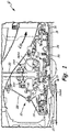
- FIG. 1 shows a portion of gas turbine engine 10 above engine centerline C L .
- Gas turbine engine 10 includes a bearing compartment 12, bearings 14, 14A, and 14AA, a high pressure compressor shaft 16, a low pressure turbine shaft 18, tower shafts 20, a fan shaft 22, a coupling 24, bevel gears 26, an outer housing 28, a cross-over housing 30, an inter-shaft seal assembly 32, seats (plates) 34, spacers 36, and a core flow path C fp .
- the bearing compartment 12 in the illustrated embodiment is the mid-bearing compartment of the gas turbine engine 10.
- the bearing compartment 12 houses the bearings 14, 14A and 14AA, which are disposed around and support the high pressure compressor shaft 16, the low pressure turbine shaft 18, the tower shafts 20 (only a single low spool tower shaft is shown in FIG. 1 ) and the fan shaft 22.
- the bearings 14 support the high pressure compressor shaft 16, the low pressure turbine shaft 18, and the fan shaft 22.
- the bearings 14A and 14AA support the tower shafts 20.
- the high pressure compressor shaft 16 is disposed radially outward of and spaced apart from the low pressure turbine shaft 18.
- the coupling 24 connects the fan shaft 22 to the tower shafts 20 via the bevel gears 26.
- the outer housing 28 extends annularly around and is disposed axially forward of components such as the bearings 14 and tower shafts 20.
- the outer housing (also called a bearing support or front cover) 28 extends radially from adjacent the casing that defines the core flow path C fp to interface with the coupling 24, and additionally connects to the cross-over housing 30.
- the cross-over housing 30 extends from the outer housing 28 and interfaces and supports the bearing sets 14A and 14AA disposed around the tower shafts 20.
- the inter-shaft seal assembly 32 is disposed radially inward of the cross-over housing 30 and axially between the coupling 24 and the high pressure compressor shaft 16.
- the inter-shaft seal assembly 32 interfaces with the seats (also called seal runners) 34.
- the seats 34 are axially abutted by the spacers 36, and the seats 34 and spacers 36 are disposed radially along the outer diameter of the high pressure compressor shaft 16 and the coupling 24.
- the high pressure compressor shaft 16 connects a high pressure compressor section of the gas turbine engine 10 with a high pressure turbine section of the engine 10. Together the high pressure compressor shaft 16, the high pressure compressor section, and the high pressure turbine section comprise a high pressure spool of the engine 10.
- the low pressure turbine shaft 18 connects a fan section (via the fan shaft 22) with a low pressure compressor section and a low pressure turbine section of the engine 10. Together these sections and components comprise a low pressure spool of the engine 10.
- a gas flow passes through core flow path C fp to rotate the high pressure and low pressure spools to extract energy from the gas flow and produce thrust. Additionally, gas flow bypasses the core flow path C fp and rotates the fan to extract additional energy and thrust from the gas flow passing through a nacelle portion of the engine 10.
- the bearing compartment 12 circumscribes the shafts 16, 18, and 22 and bearings 14, 14A, and 14AA and acts to contain a lubricant oil that is supplied to the bearing compartment 12 to lubricate and cool the bearings 14, 14A, 14AA, during operation of the gas turbine engine 10.
- the bearings 14 support the high pressure compressor shaft 16, the low pressure turbine shaft 18, and the fan shaft 24 (also called a stub shaft) and allow the shafts 16, 18, and 22 to rotate relative to the stator engine casing.
- the bearings 14A and 14AA support the tower shafts 20 and allow the tower shafts 20 to rotate relative to the stator engine casing.
- the cross-over housing 30 supports the inter-shaft seal assembly 32.
- the structure and operational principles of the inter-shaft seal assembly 32 are well know in the art and is described, for example in United States Patent Number 6,196,790 to Sheridan et al. , which is incorporated herein by reference.
- the inter-shaft seal assembly 32 prevents a cooling gas circulated between the shafts 16 and 18 from leaking into the lubricant supplied portions of the bearing compartment 12. Additionally, the inter-shaft seal assembly 32 prevents the lubricant from leaking into the volume between the shafts 16 and 18. To accomplish this, the inter-shaft seal assembly 32 has carbon seals that are biased to ride against the seats 34, which are also constructed of carbon material. The spacer 36 abuts the seats 34 to provide necessary spacing between the rearward bearing 14 and the coupling 24.
- FIG. 2A shows a perspective view of a portion of the cross-over housing 30. Additionally, FIG. 2A shows a carbon seal housing 38 that is part of the inter-shaft seal assembly 32 ( FIG. 1 ). The other components of the inter-shaft seal assembly 32, the bearing compartment 12, and the shafts 16 and 18 are removed in FIG. 2A to better illustrate the carbon seal housing 38 and a removable linkage 40.
- the cross-over housing 30 includes integral tabs 42 and main body 44.
- the inter-shaft seal housing 38 includes integral tabs 46, and a flange portion 48.
- the integral tabs 42 and 46 include mounting holes 49.
- the cross-over housing 30 extends circumferentially so as to have an axis of symmetry that substantially aligns with centerline of the gas turbine 10.
- the carbon seal housing 38 is disposed radially inward of the cross-over housing 30.
- the removable linkage 40 and the integral tabs 42 and 46 connect the carbon seal housing 38 to the cross-over housing 30.
- the integral tabs 42 extend radially inward from the main body 44 of the cross-over housing 30 and each of the integral tabs 42 has a mounting hole 49 that extends therethrough.
- the integral tabs 42 interface with the integral tabs 46 that extend radially outward from the flange portion 48 of the carbon seal housing 38.
- Each of the integral tabs 46 has a mounting hole 49 that extends therethrough.
- the integral tabs 42 and 46 are adapted to receive fasteners in the aligned mounting holes 49 to connect together.
- a smaller integral member 46A extends outward from the flange portion 48 to interface with the removable linkage 40.
- the removable linkage 40 and the integral member 46A are also fastened together with a fastener that is received in a mounting hole 49A.
- three pairs of the integral tabs 42 and 46 and one removable linkage 40 are shown in FIG. 2A , in other embodiments the number of integral tabs and removable linkages may vary.
- FIG. 2B illustrates a portion of the cross-over housing 30 that has a slot 50 for receiving the removable linkage 40.
- FIG. 2B illustrates a distal portion of the removable linkage 40 that includes brackets 52A and 52B with mounting holes 53 extending therethrough.
- the slot 50 extends circumferentially around a portion of the main body 44 of the cross-over housing 30 and is positioned radially outward of where the integral member 46A is located.
- the slot 50 is sized so as to allow an upper portion of the removable linkage 40 to extend radially inward and connect with the carbon seal housing 38.
- the distal portion of the removable linkage 40 with the brackets 52A and 52B extend away from the slot 50 to interface with and connect to the outer circumference of the cross-over housing 30 with fasteners (not shown) received in the mounting holes 53.
- the design of the cross-over housing 30, the carbon seal housing 38, and the removable linkage 40 allow for improved ease of assembly and disassembly, yet allows the resulting assembly to meet structural integrity requirements such as those with regard to vibratory response during operation of the engine 10.
- the removable linkage 40 can be inserted and removed though the slot 50 from a position radially outward of the cross-over housing 30 and can be secured to the outer circumference of the cross-over housing 30. Additionally, the geometry of the removable linkage 40 mistake proofs installation as the removable linkage 40 can be rotated 180 degrees and still be installed to couple with the cross-over housing 30.
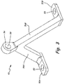
- FIG. 3 shows one embodiment of the removable linkage 40.
- the linkage 40 includes a first bracket 54, a first leg 56A, and a second leg 56B.
- the first bracket includes mounting holes 58.
- the first bracket 54 is adapted to fit through slot 50 ( FIG. 2B ) and interface with the integral member 46A so that mounting holes 58 generally align with mounting holes 49A.
- the legs 56A and 56B intersect one another adjacent to the first bracket 54 and are connected thereto.
- the first leg 56A and the second leg 56B are substantially aligned along a common plane so as to extend through the slot 50 ( FIG. 2B ) together.
- the first leg 56A and the second leg 56B have symmetry with respect to a plane extending through the bracket 54.
- the bracket 52A extends from a distal portion of the first leg 56A and the bracket 52B extends from a distal portion of the second leg 56B.
- the brackets 52A and 52B are orientated so as to extend in opposite directions from one another in substantially a same plane. This configuration allows the brackets 52A and 52B to interface with the outer circumference of the cross-over housing 30 to either side of the slot 50 and provides for improved load distribution through the removable linkage 40.
- the brackets 52A and 52B extend along a plane that is substantially perpendicular to plane that the first leg 56A and second leg 56B extend along. Additionally, the plane the brackets 52A and 52B extend along is substantially perpendicular to a plane along which the first bracket 54 extends.
Landscapes
- Engineering & Computer Science (AREA)
- Mechanical Engineering (AREA)
- General Engineering & Computer Science (AREA)
- Chemical & Material Sciences (AREA)
- Combustion & Propulsion (AREA)
- Turbine Rotor Nozzle Sealing (AREA)
- Sealing Devices (AREA)
- Gasket Seals (AREA)
Applications Claiming Priority (2)
| Application Number | Priority Date | Filing Date | Title |
|---|---|---|---|
| US13/013,885 US8919134B2 (en) | 2011-01-26 | 2011-01-26 | Intershaft seal with support linkage |
| EP12152735.2A EP2481887B1 (de) | 2011-01-26 | 2012-01-26 | Zwischenwellendichtung mit Stützverbindung |
Related Parent Applications (2)
| Application Number | Title | Priority Date | Filing Date |
|---|---|---|---|
| EP12152735.2A Division-Into EP2481887B1 (de) | 2011-01-26 | 2012-01-26 | Zwischenwellendichtung mit Stützverbindung |
| EP12152735.2A Division EP2481887B1 (de) | 2011-01-26 | 2012-01-26 | Zwischenwellendichtung mit Stützverbindung |
Publications (2)
| Publication Number | Publication Date |
|---|---|
| EP3396113A1 true EP3396113A1 (de) | 2018-10-31 |
| EP3396113B1 EP3396113B1 (de) | 2020-06-17 |
Family
ID=45528989
Family Applications (2)
| Application Number | Title | Priority Date | Filing Date |
|---|---|---|---|
| EP12152735.2A Active EP2481887B1 (de) | 2011-01-26 | 2012-01-26 | Zwischenwellendichtung mit Stützverbindung |
| EP18175394.8A Active EP3396113B1 (de) | 2011-01-26 | 2012-01-26 | Zwischenwellendichtung mit stützverbindung |
Family Applications Before (1)
| Application Number | Title | Priority Date | Filing Date |
|---|---|---|---|
| EP12152735.2A Active EP2481887B1 (de) | 2011-01-26 | 2012-01-26 | Zwischenwellendichtung mit Stützverbindung |
Country Status (2)
| Country | Link |
|---|---|
| US (1) | US8919134B2 (de) |
| EP (2) | EP2481887B1 (de) |
Families Citing this family (11)
| Publication number | Priority date | Publication date | Assignee | Title |
|---|---|---|---|---|
| US9097141B2 (en) * | 2011-09-15 | 2015-08-04 | Pratt & Whitney Canada Corp. | Axial bolting arrangement for mid turbine frame |
| US9163522B2 (en) | 2012-08-21 | 2015-10-20 | United Technologies Corporation | Spring carrier and removable seal carrier |
| US8955809B2 (en) * | 2012-12-05 | 2015-02-17 | Hamilton Sundstrand Corporation | Three-way mount bracket for aircraft cabin air supply system |
| US10197150B2 (en) | 2015-11-23 | 2019-02-05 | United Technologies Corporation | Gear baffle configured with lubricant outlet passage |
| US10221937B2 (en) | 2016-04-05 | 2019-03-05 | United Technologies Corporation | Slotted oil baffle for gears |
| US10364880B2 (en) | 2017-01-05 | 2019-07-30 | United Technologies Corporation | Oil quieting direction control baffle |
| US10634062B2 (en) * | 2017-03-21 | 2020-04-28 | United Technologies Corporation | Two-shaft tower shaft support |
| US10655679B2 (en) | 2017-04-07 | 2020-05-19 | United Technologies Corporation | Oil control for seal plates |
| US10260423B2 (en) * | 2017-04-18 | 2019-04-16 | United Technologies Corporation | Towershaft support |
| US10830078B2 (en) * | 2018-09-14 | 2020-11-10 | Raytheon Technologies Corporation | Shaft seal assembly for a turbine engine |
| US11215077B1 (en) * | 2020-08-17 | 2022-01-04 | Raytheon Technologies Corporation | Integral gear support and bearing damper pedestal |
Citations (4)
| Publication number | Priority date | Publication date | Assignee | Title |
|---|---|---|---|---|
| US3397855A (en) * | 1966-12-01 | 1968-08-20 | United Aircraft Canada | Rear mount system for aircraft engines |
| US6196790B1 (en) | 1998-12-17 | 2001-03-06 | United Technologies Corporation | Seal assembly for an intershaft seal in a gas turbine engine |
| US20020184890A1 (en) * | 2001-06-06 | 2002-12-12 | Snecma Moteurs | Resilient mount for a CMC combustion of a turbomachine in a metal casing |
| EP1439350A2 (de) * | 2003-01-14 | 2004-07-21 | General Electric Company | Trägeranordnung für eine Gasturbinenbrennkammer |
Family Cites Families (3)
| Publication number | Priority date | Publication date | Assignee | Title |
|---|---|---|---|---|
| FR2770486B1 (fr) * | 1997-11-06 | 2000-01-28 | Aerospatiale | Dispositif d'accrochage d'un moteur sur un aeronef |
| US6132168A (en) | 1998-12-23 | 2000-10-17 | United Technologies Corporation | Balancing a pressure drop across ring seals in gas turbine engines |
| US6996968B2 (en) | 2003-12-17 | 2006-02-14 | United Technologies Corporation | Bifurcated oil scavenge system for a gas turbine engine |
-
2011
- 2011-01-26 US US13/013,885 patent/US8919134B2/en active Active
-
2012
- 2012-01-26 EP EP12152735.2A patent/EP2481887B1/de active Active
- 2012-01-26 EP EP18175394.8A patent/EP3396113B1/de active Active
Patent Citations (4)
| Publication number | Priority date | Publication date | Assignee | Title |
|---|---|---|---|---|
| US3397855A (en) * | 1966-12-01 | 1968-08-20 | United Aircraft Canada | Rear mount system for aircraft engines |
| US6196790B1 (en) | 1998-12-17 | 2001-03-06 | United Technologies Corporation | Seal assembly for an intershaft seal in a gas turbine engine |
| US20020184890A1 (en) * | 2001-06-06 | 2002-12-12 | Snecma Moteurs | Resilient mount for a CMC combustion of a turbomachine in a metal casing |
| EP1439350A2 (de) * | 2003-01-14 | 2004-07-21 | General Electric Company | Trägeranordnung für eine Gasturbinenbrennkammer |
Also Published As
| Publication number | Publication date |
|---|---|
| EP2481887A3 (de) | 2017-12-06 |
| EP2481887B1 (de) | 2019-04-10 |
| US8919134B2 (en) | 2014-12-30 |
| US20120186270A1 (en) | 2012-07-26 |
| EP3396113B1 (de) | 2020-06-17 |
| EP2481887A2 (de) | 2012-08-01 |
Similar Documents
| Publication | Publication Date | Title |
|---|---|---|
| EP3396113A1 (de) | Zwischenwellendichtung mit stützverbindung | |
| US7195446B2 (en) | Counter-rotating turbine engine and method of assembling same | |
| EP2657463B1 (de) | Ölschöpfverteiler | |
| CA2762810C (en) | Variable geometry vane system for gas turbine engines | |
| US9746029B1 (en) | Bearing | |
| EP3045657B1 (de) | Dichtungssystem zwischen einem lagergehäuse und einer schnittstelle zwischen zwei wellen eines gasturbinentriebwerks | |
| US9546560B2 (en) | Compact double grounded mechanical carbon seal | |
| US10001166B2 (en) | Gas distribution labyrinth for bearing pad | |
| EP2589759B1 (de) | Mittelturbinen-Lagerträger | |
| US10704600B2 (en) | Bearing | |
| US10914195B2 (en) | Rotary machine with gas bearings | |
| CN120312356A (zh) | 气体轴承密封件 | |
| JP2017053343A (ja) | ガスタービンエンジン用の軸受ハウジング及び関連する軸受組立体 | |
| US11982201B2 (en) | Damper system for an engine shaft | |
| EP2412940B1 (de) | Drehbare Komponentenfassung für einen Gasturbinenmotor | |
| EP4124724B1 (de) | Wälzlageranordnung für einen gasturbinenmotor | |
| EP4361403A1 (de) | Leitungsdurchführung mit zellmaterial | |
| US11795839B2 (en) | Structural assembly for a gas turbine engine | |
| US11639688B1 (en) | Mounting for planetary gear systems | |
| CN114080491B (zh) | 涡轮机的输出轴承支撑件 | |
| EP4621192A2 (de) | Lagerölverteilungsschema | |
| US20250043726A1 (en) | Containment ring cavity pressurization system |
Legal Events
| Date | Code | Title | Description |
|---|---|---|---|
| PUAI | Public reference made under article 153(3) epc to a published international application that has entered the european phase |
Free format text: ORIGINAL CODE: 0009012 |
|
| STAA | Information on the status of an ep patent application or granted ep patent |
Free format text: STATUS: THE APPLICATION HAS BEEN PUBLISHED |
|
| AC | Divisional application: reference to earlier application |
Ref document number: 2481887 Country of ref document: EP Kind code of ref document: P |
|
| AK | Designated contracting states |
Kind code of ref document: A1 Designated state(s): AL AT BE BG CH CY CZ DE DK EE ES FI FR GB GR HR HU IE IS IT LI LT LU LV MC MK MT NL NO PL PT RO RS SE SI SK SM TR |
|
| AX | Request for extension of the european patent |
Extension state: BA ME |
|
| STAA | Information on the status of an ep patent application or granted ep patent |
Free format text: STATUS: REQUEST FOR EXAMINATION WAS MADE |
|
| 17P | Request for examination filed |
Effective date: 20190429 |
|
| RBV | Designated contracting states (corrected) |
Designated state(s): AL AT BE BG CH CY CZ DE DK EE ES FI FR GB GR HR HU IE IS IT LI LT LU LV MC MK MT NL NO PL PT RO RS SE SI SK SM TR |
|
| GRAP | Despatch of communication of intention to grant a patent |
Free format text: ORIGINAL CODE: EPIDOSNIGR1 |
|
| STAA | Information on the status of an ep patent application or granted ep patent |
Free format text: STATUS: GRANT OF PATENT IS INTENDED |
|
| RIC1 | Information provided on ipc code assigned before grant |
Ipc: F01D 11/00 20060101AFI20190923BHEP Ipc: F01D 25/16 20060101ALI20190923BHEP Ipc: F02C 7/28 20060101ALI20190923BHEP Ipc: F01D 25/18 20060101ALI20190923BHEP Ipc: F02C 7/36 20060101ALI20190923BHEP |
|
| INTG | Intention to grant announced |
Effective date: 20191025 |
|
| RIN1 | Information on inventor provided before grant (corrected) |
Inventor name: TATMAN, NEIL L. Inventor name: LARSON, CHRISTOPHER J. |
|
| GRAJ | Information related to disapproval of communication of intention to grant by the applicant or resumption of examination proceedings by the epo deleted |
Free format text: ORIGINAL CODE: EPIDOSDIGR1 |
|
| STAA | Information on the status of an ep patent application or granted ep patent |
Free format text: STATUS: REQUEST FOR EXAMINATION WAS MADE |
|
| GRAP | Despatch of communication of intention to grant a patent |
Free format text: ORIGINAL CODE: EPIDOSNIGR1 |
|
| STAA | Information on the status of an ep patent application or granted ep patent |
Free format text: STATUS: GRANT OF PATENT IS INTENDED |
|
| INTC | Intention to grant announced (deleted) | ||
| INTG | Intention to grant announced |
Effective date: 20200403 |
|
| GRAS | Grant fee paid |
Free format text: ORIGINAL CODE: EPIDOSNIGR3 |
|
| GRAA | (expected) grant |
Free format text: ORIGINAL CODE: 0009210 |
|
| STAA | Information on the status of an ep patent application or granted ep patent |
Free format text: STATUS: THE PATENT HAS BEEN GRANTED |
|
| AC | Divisional application: reference to earlier application |
Ref document number: 2481887 Country of ref document: EP Kind code of ref document: P |
|
| AK | Designated contracting states |
Kind code of ref document: B1 Designated state(s): AL AT BE BG CH CY CZ DE DK EE ES FI FR GB GR HR HU IE IS IT LI LT LU LV MC MK MT NL NO PL PT RO RS SE SI SK SM TR |
|
| REG | Reference to a national code |
Ref country code: GB Ref legal event code: FG4D |
|
| REG | Reference to a national code |
Ref country code: CH Ref legal event code: EP |
|
| REG | Reference to a national code |
Ref country code: DE Ref legal event code: R096 Ref document number: 602012070833 Country of ref document: DE |
|
| REG | Reference to a national code |
Ref country code: IE Ref legal event code: FG4D |
|
| REG | Reference to a national code |
Ref country code: AT Ref legal event code: REF Ref document number: 1281538 Country of ref document: AT Kind code of ref document: T Effective date: 20200715 |
|
| PG25 | Lapsed in a contracting state [announced via postgrant information from national office to epo] |
Ref country code: LT Free format text: LAPSE BECAUSE OF FAILURE TO SUBMIT A TRANSLATION OF THE DESCRIPTION OR TO PAY THE FEE WITHIN THE PRESCRIBED TIME-LIMIT Effective date: 20200617 Ref country code: NO Free format text: LAPSE BECAUSE OF FAILURE TO SUBMIT A TRANSLATION OF THE DESCRIPTION OR TO PAY THE FEE WITHIN THE PRESCRIBED TIME-LIMIT Effective date: 20200917 Ref country code: GR Free format text: LAPSE BECAUSE OF FAILURE TO SUBMIT A TRANSLATION OF THE DESCRIPTION OR TO PAY THE FEE WITHIN THE PRESCRIBED TIME-LIMIT Effective date: 20200918 Ref country code: FI Free format text: LAPSE BECAUSE OF FAILURE TO SUBMIT A TRANSLATION OF THE DESCRIPTION OR TO PAY THE FEE WITHIN THE PRESCRIBED TIME-LIMIT Effective date: 20200617 Ref country code: SE Free format text: LAPSE BECAUSE OF FAILURE TO SUBMIT A TRANSLATION OF THE DESCRIPTION OR TO PAY THE FEE WITHIN THE PRESCRIBED TIME-LIMIT Effective date: 20200617 |
|
| REG | Reference to a national code |
Ref country code: LT Ref legal event code: MG4D |
|
| REG | Reference to a national code |
Ref country code: NL Ref legal event code: MP Effective date: 20200617 |
|
| PG25 | Lapsed in a contracting state [announced via postgrant information from national office to epo] |
Ref country code: HR Free format text: LAPSE BECAUSE OF FAILURE TO SUBMIT A TRANSLATION OF THE DESCRIPTION OR TO PAY THE FEE WITHIN THE PRESCRIBED TIME-LIMIT Effective date: 20200617 Ref country code: RS Free format text: LAPSE BECAUSE OF FAILURE TO SUBMIT A TRANSLATION OF THE DESCRIPTION OR TO PAY THE FEE WITHIN THE PRESCRIBED TIME-LIMIT Effective date: 20200617 Ref country code: BG Free format text: LAPSE BECAUSE OF FAILURE TO SUBMIT A TRANSLATION OF THE DESCRIPTION OR TO PAY THE FEE WITHIN THE PRESCRIBED TIME-LIMIT Effective date: 20200917 Ref country code: LV Free format text: LAPSE BECAUSE OF FAILURE TO SUBMIT A TRANSLATION OF THE DESCRIPTION OR TO PAY THE FEE WITHIN THE PRESCRIBED TIME-LIMIT Effective date: 20200617 |
|
| REG | Reference to a national code |
Ref country code: AT Ref legal event code: MK05 Ref document number: 1281538 Country of ref document: AT Kind code of ref document: T Effective date: 20200617 |
|
| PG25 | Lapsed in a contracting state [announced via postgrant information from national office to epo] |
Ref country code: NL Free format text: LAPSE BECAUSE OF FAILURE TO SUBMIT A TRANSLATION OF THE DESCRIPTION OR TO PAY THE FEE WITHIN THE PRESCRIBED TIME-LIMIT Effective date: 20200617 Ref country code: AL Free format text: LAPSE BECAUSE OF FAILURE TO SUBMIT A TRANSLATION OF THE DESCRIPTION OR TO PAY THE FEE WITHIN THE PRESCRIBED TIME-LIMIT Effective date: 20200617 |
|
| PG25 | Lapsed in a contracting state [announced via postgrant information from national office to epo] |
Ref country code: ES Free format text: LAPSE BECAUSE OF FAILURE TO SUBMIT A TRANSLATION OF THE DESCRIPTION OR TO PAY THE FEE WITHIN THE PRESCRIBED TIME-LIMIT Effective date: 20200617 Ref country code: RO Free format text: LAPSE BECAUSE OF FAILURE TO SUBMIT A TRANSLATION OF THE DESCRIPTION OR TO PAY THE FEE WITHIN THE PRESCRIBED TIME-LIMIT Effective date: 20200617 Ref country code: CZ Free format text: LAPSE BECAUSE OF FAILURE TO SUBMIT A TRANSLATION OF THE DESCRIPTION OR TO PAY THE FEE WITHIN THE PRESCRIBED TIME-LIMIT Effective date: 20200617 Ref country code: PT Free format text: LAPSE BECAUSE OF FAILURE TO SUBMIT A TRANSLATION OF THE DESCRIPTION OR TO PAY THE FEE WITHIN THE PRESCRIBED TIME-LIMIT Effective date: 20201019 Ref country code: IT Free format text: LAPSE BECAUSE OF FAILURE TO SUBMIT A TRANSLATION OF THE DESCRIPTION OR TO PAY THE FEE WITHIN THE PRESCRIBED TIME-LIMIT Effective date: 20200617 Ref country code: AT Free format text: LAPSE BECAUSE OF FAILURE TO SUBMIT A TRANSLATION OF THE DESCRIPTION OR TO PAY THE FEE WITHIN THE PRESCRIBED TIME-LIMIT Effective date: 20200617 Ref country code: EE Free format text: LAPSE BECAUSE OF FAILURE TO SUBMIT A TRANSLATION OF THE DESCRIPTION OR TO PAY THE FEE WITHIN THE PRESCRIBED TIME-LIMIT Effective date: 20200617 Ref country code: SM Free format text: LAPSE BECAUSE OF FAILURE TO SUBMIT A TRANSLATION OF THE DESCRIPTION OR TO PAY THE FEE WITHIN THE PRESCRIBED TIME-LIMIT Effective date: 20200617 |
|
| PG25 | Lapsed in a contracting state [announced via postgrant information from national office to epo] |
Ref country code: IS Free format text: LAPSE BECAUSE OF FAILURE TO SUBMIT A TRANSLATION OF THE DESCRIPTION OR TO PAY THE FEE WITHIN THE PRESCRIBED TIME-LIMIT Effective date: 20201017 Ref country code: PL Free format text: LAPSE BECAUSE OF FAILURE TO SUBMIT A TRANSLATION OF THE DESCRIPTION OR TO PAY THE FEE WITHIN THE PRESCRIBED TIME-LIMIT Effective date: 20200617 Ref country code: SK Free format text: LAPSE BECAUSE OF FAILURE TO SUBMIT A TRANSLATION OF THE DESCRIPTION OR TO PAY THE FEE WITHIN THE PRESCRIBED TIME-LIMIT Effective date: 20200617 |
|
| REG | Reference to a national code |
Ref country code: DE Ref legal event code: R097 Ref document number: 602012070833 Country of ref document: DE |
|
| RAP2 | Party data changed (patent owner data changed or rights of a patent transferred) |
Owner name: RAYTHEON TECHNOLOGIES CORPORATION |
|
| PLBE | No opposition filed within time limit |
Free format text: ORIGINAL CODE: 0009261 |
|
| STAA | Information on the status of an ep patent application or granted ep patent |
Free format text: STATUS: NO OPPOSITION FILED WITHIN TIME LIMIT |
|
| PG25 | Lapsed in a contracting state [announced via postgrant information from national office to epo] |
Ref country code: DK Free format text: LAPSE BECAUSE OF FAILURE TO SUBMIT A TRANSLATION OF THE DESCRIPTION OR TO PAY THE FEE WITHIN THE PRESCRIBED TIME-LIMIT Effective date: 20200617 |
|
| 26N | No opposition filed |
Effective date: 20210318 |
|
| PG25 | Lapsed in a contracting state [announced via postgrant information from national office to epo] |
Ref country code: SI Free format text: LAPSE BECAUSE OF FAILURE TO SUBMIT A TRANSLATION OF THE DESCRIPTION OR TO PAY THE FEE WITHIN THE PRESCRIBED TIME-LIMIT Effective date: 20200617 |
|
| PG25 | Lapsed in a contracting state [announced via postgrant information from national office to epo] |
Ref country code: MC Free format text: LAPSE BECAUSE OF FAILURE TO SUBMIT A TRANSLATION OF THE DESCRIPTION OR TO PAY THE FEE WITHIN THE PRESCRIBED TIME-LIMIT Effective date: 20200617 |
|
| REG | Reference to a national code |
Ref country code: CH Ref legal event code: PL |
|
| PG25 | Lapsed in a contracting state [announced via postgrant information from national office to epo] |
Ref country code: LU Free format text: LAPSE BECAUSE OF NON-PAYMENT OF DUE FEES Effective date: 20210126 |
|
| REG | Reference to a national code |
Ref country code: BE Ref legal event code: MM Effective date: 20210131 |
|
| PG25 | Lapsed in a contracting state [announced via postgrant information from national office to epo] |
Ref country code: CH Free format text: LAPSE BECAUSE OF NON-PAYMENT OF DUE FEES Effective date: 20210131 Ref country code: LI Free format text: LAPSE BECAUSE OF NON-PAYMENT OF DUE FEES Effective date: 20210131 |
|
| PG25 | Lapsed in a contracting state [announced via postgrant information from national office to epo] |
Ref country code: IE Free format text: LAPSE BECAUSE OF NON-PAYMENT OF DUE FEES Effective date: 20210126 |
|
| PG25 | Lapsed in a contracting state [announced via postgrant information from national office to epo] |
Ref country code: BE Free format text: LAPSE BECAUSE OF NON-PAYMENT OF DUE FEES Effective date: 20210131 |
|
| PG25 | Lapsed in a contracting state [announced via postgrant information from national office to epo] |
Ref country code: CY Free format text: LAPSE BECAUSE OF FAILURE TO SUBMIT A TRANSLATION OF THE DESCRIPTION OR TO PAY THE FEE WITHIN THE PRESCRIBED TIME-LIMIT Effective date: 20200617 |
|
| P01 | Opt-out of the competence of the unified patent court (upc) registered |
Effective date: 20230521 |
|
| PG25 | Lapsed in a contracting state [announced via postgrant information from national office to epo] |
Ref country code: HU Free format text: LAPSE BECAUSE OF FAILURE TO SUBMIT A TRANSLATION OF THE DESCRIPTION OR TO PAY THE FEE WITHIN THE PRESCRIBED TIME-LIMIT; INVALID AB INITIO Effective date: 20120126 |
|
| PG25 | Lapsed in a contracting state [announced via postgrant information from national office to epo] |
Ref country code: MK Free format text: LAPSE BECAUSE OF FAILURE TO SUBMIT A TRANSLATION OF THE DESCRIPTION OR TO PAY THE FEE WITHIN THE PRESCRIBED TIME-LIMIT Effective date: 20200617 |
|
| PG25 | Lapsed in a contracting state [announced via postgrant information from national office to epo] |
Ref country code: TR Free format text: LAPSE BECAUSE OF FAILURE TO SUBMIT A TRANSLATION OF THE DESCRIPTION OR TO PAY THE FEE WITHIN THE PRESCRIBED TIME-LIMIT Effective date: 20200617 |
|
| PG25 | Lapsed in a contracting state [announced via postgrant information from national office to epo] |
Ref country code: MT Free format text: LAPSE BECAUSE OF FAILURE TO SUBMIT A TRANSLATION OF THE DESCRIPTION OR TO PAY THE FEE WITHIN THE PRESCRIBED TIME-LIMIT Effective date: 20200617 |
|
| REG | Reference to a national code |
Ref country code: DE Ref legal event code: R081 Ref document number: 602012070833 Country of ref document: DE Owner name: RTX CORPORATION (N.D.GES.D. STAATES DELAWARE),, US Free format text: FORMER OWNER: UNITED TECHNOLOGIES CORPORATION, FARMINGTON, CONN., US |
|
| PGFP | Annual fee paid to national office [announced via postgrant information from national office to epo] |
Ref country code: GB Payment date: 20251220 Year of fee payment: 15 |
|
| PGFP | Annual fee paid to national office [announced via postgrant information from national office to epo] |
Ref country code: FR Payment date: 20251217 Year of fee payment: 15 |
|
| PGFP | Annual fee paid to national office [announced via postgrant information from national office to epo] |
Ref country code: DE Payment date: 20251217 Year of fee payment: 15 |